Blaze PowerZone Connect 122D Installation Manual & User Manual
Hide thumbs
Also See for PowerZone Connect 122D:
- Quick start manual (4 pages) ,
- Installation manual & user manual (28 pages)

Related Manuals for Blaze PowerZone Connect 122D


Summary of Contents for Blaze PowerZone Connect 122D
- Page 1 INSTALLATION GUIDE / USER MANUAL PowerZone™ Connect 122/122D • PowerZone™ Connect 252 PowerZone™ Connect 254 • PowerZone™ Connect 504/504D...
-
Page 2: Technical Notices
Technical and Safety Notices Safety and Environmental Notices Please read the following important technical, safety and environmental notices before installing and using Note: The intent of the lightning flash with arrowhead symbol your amplifier. in a triangle is to alert the user to the presence of uninsulated Technical Notices “dangerous”... -
Page 3: Important Safety Instructions
Technical and Safety Notices Important Safety Instructions Environmental Statement Read these instructions. This product complies with international Keep these instructions. directives, including but not limited to the Heed all warnings. Restriction of Hazardous Substances (RoHS) Follow all instructions. in electrical and electronic equipment, the Do not use this apparatus near water. -
Page 4: Introduction And Overview
Introduction and Overview 1. Introduction 2. Amplifier Overview Blaze PowerZone™ Connect power amplifiers have PowerZone™ Connect 122/122D, 252, 254 and 504/504D been designed to provide configurable, consistent and amplifiers are half rack width, 1U format power amplifiers that can drive both conventional low impedance (Lo-Z, 4Ω... -
Page 5: Carton Contents
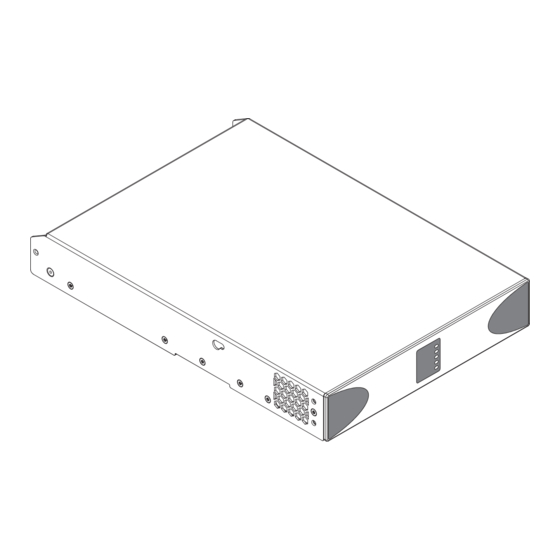
• Adhesive rubber feet x 4 • Document pack PowerZone™ Connect amplifiers are able to be controlled remotely using the Blaze Wall-S1 control panel. The Wall-S1 is an Ethernet connected wall-mounted device able to control Blaze PowerZone™ Connect amplifier volume and input source selection. - Page 6 Overview Diagram 1a PowerZone™ Connect two channel amplifier dimensions. (Shaded area defines ventilation space.) 44 mm 1.7 in 80 mm 3.1 in 25 mm 1.0 in 213 mm 8.4 in 220 mm 8.7 in Diagram 1b PowerZone™ Connect four channel amplifier dimensions. (Shaded area defines ventilation space.) 44 mm 1.7 in...
-
Page 7: Installation
Installation 4. Installation Note: The rack mounting and desk/wall mounting components described and illustrated in Sections 4.1 to 4.3 are not supplied with PowerZone™ Connect amplifiers but are available to purchase as accessories. Contact your amplifier re-seller for more information. Diagram 3a 4.1 PowerZone™... -
Page 8: Free-Standing
Installation 4.2 Free-standing Diagram 4a PowerZone™ Connect If not installed in an equipment rack, PowerZone™ Connect with desk/wall Mounting Plate and adhesive feet. amplifiers can be placed free-standing on a flat surface. 2 positions and 4 positions. Adhesive rubber feet are supplied for this purpose. PowerZone™... -
Page 9: Mains Power Connection
Configuration 5. Configuration 4. Open a laptop or desktop web browser and enter the Before making input, output and GPIO connections, an address http:/ /192.168.64.100. The PowerZone™ Control Web initial PowerZone™ Connect amplifier configuration App interface will open to enable amplifier configuration as should be established. -
Page 10: Configuration Menus
Configuration 5.3 Configuration Menus 5.3.1 Input Tab The Input Tab provides the following configuration parameters Opening a web browser that is network connected to for each amplifier input channel: a PowerZone™ Connect amplifier initially displays the • Input name PowerZone™ Control Web App Dashboard illustrated in •... - Page 11 Configuration Select mix function Mix name - type to edit Adjust mix input level Select and adjust required EQ stages Diagram 5C Diagram 5D Input EQ display Input Mix display A pink noise or sine wave audio signal generator, appropriate for audio system testing and set up, can also be enabled, disabled, and adjusted for gain and frequency via the Input Tab.
- Page 12 Configuration Note: Input Priority and Input Ducking parameters can be either set to default values or their Threshold, Attack, Hold and Release values Select zone set as required. Input Priority can also be set to ignore the volume level set for the specified zone and take a specific override volume. •...
- Page 13 Section Select output 5.3.5. A variety of speaker preset files are available for download from the Blaze website: www.blaze-audio.com. 2. Select the appropriate ‘.zcp’ format speaker preset data file to import from either a Library or a computer folder.
- Page 14 Configuration Diagram 5J Diagram 5K Speaker Preset applied Speaker Preset parameter adjustment • The FIR preset menu enables FIR (Finite Impulse Response) Note: In automatic mode, the peak limiter parameters adjust based equalization filter coefficients generated by external automatically in response to Crossover & Gain high-pass filter speaker measurement software to be imported and applied settings.
- Page 15 Device menu. • The External Devices menu enables Blaze Wall-S1 control panels to be paired with an amplifier and configured. Each individual amplifier zone to be controlled requires its own Wall-S1 unit.
- Page 16 Note: A variety of speaker preset files are available for download Library version - type to edit from the Blaze website: www.blaze-audio.com. • The Security menu enables a password to be set in order to protect against unauthorised access to the amplifier Delete library Control Web App.
- Page 17 Configuration 5.4 Setup and Signal Routing Thanks to their network based configuration features, PowerZone™ Connect amplifiers offer considerable versatility in terms of sources, signal routing, installation zones and output modes. Inputs can be freely assigned to installation zones, and those zones assigned freely to the available amplifier outputs in either Lo-Z or Hi-Z modes.
- Page 18 Configuration 5.4.1 Input Setup 5.4.2 Zone Setup & Routing Open the configuration Dashboard and select the Input Tab. Open the configuration Dashboard and select the Zone Tab. The Input Tab is shown in Diagram 5B. The Zone Tab is shown in Diagram 5E. •...
- Page 19 Configuration 5.5 GPIO Setup and Connection Diagram 5P GPIO Settings Menu PowerZone™ Connect amplifiers provide a GPIO socket that enables remote control of volume, standby, mute and trigger functions. The GPIO connector pin functions are described in the GPIO Settings menu illustrated in Diagram 5P. The connection of GPIO based remote volume control and standby/mute are illustrated in Diagram 5Q and Diagram 5R respectively.
-
Page 20: Input Connection
Connections 6. Connections Digital Outputs PowerZone™ Connect S/PDIF stereo digital audio output PowerZone™ Connect amplifier rear panel connections connections are made via a single RCA Phono socket. The S/ are illustrated in Diagrams 6A. PDIF output signal can be routed from any input or zone and is intended to be used for daisy-chaining PowerZone™... -
Page 21: Network Connections
Connections 6.4 Speaker Cable Gauge Cable Gauge Table Lo-Z installations, 0.5dB attenuation. 4 Ω & 8 Ω loads PowerZone™ Connect speaker connection cable gauge Max Cable Max Cable Cable Cross should be chosen appropriately to reflect the type of Cable Gauge Length Length Section... - Page 22 Connections Diagram 6B Diagram 6D Balanced analog input GPIO cable connections. cable connections. 5 mm 5 mm Diagram 6C Output cable connections. Low-Z Mode 5 mm Hi-Z Mode 5 mm The exclamation point printed next to the output terminals of the amplifiers is, in addition to the CLASS 2 WIRING text, intended to alert users to the risk of hazardous voltages.
-
Page 23: Operation
Operation 7. Operation 7.2 Automatic Power Sharing PowerZone™ Connect amplifiers incorporate a power sharing Once all connections have been made and configuration feature that automatically shares the total power available options selected, PowerZone™ Connect amplifiers from the amplifier’s internal power supply across each pair of are ready for use. -
Page 24: Specifications
Output power measured @ 1% THD at 120VAC 60Hz and 230VAC 50Hz *100V line mode is @ -1dB (≈ 90 V) **504 may only Powershare across Ch1/2 and Ch3/4 Blaze Audio HQ, Pascal A/S, Ellekaer 6, DK-2730 Herlev, Denmark. hello@blaze-audio.com, www.blaze-audio.com Blaze Audio Americas, Pascal Inc., (888) 500-0109, help@blaze-audio.com, www.blaze-audio.com...
Need help?
Do you have a question about the PowerZone Connect 122D and is the answer not in the manual?
Questions and answers