Table of Contents
Advertisement
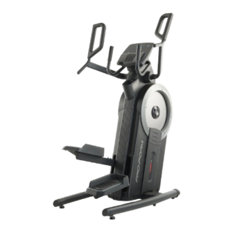
proform.com
Model No. PFEL07523.0
Serial No.
Write the serial number in the space
above for reference.
REGISTER YOUR
PRODUCT
To register your product and
activate your warranty today,
go to my.proform.com.
MEMBER CARE
For service at any time, go to
my.iFIT.com or scan the QR code.
Please do not contact the store.
CAUTION
Read all precautions and
instructions in this manual before
using this equipment. Keep this
manual for future reference.
Serial
Number
Decal
USER'S MANUAL
Advertisement
Table of Contents

Related Manuals for Pro-Form TRAINER HL PFEL07523.0


Summary of Contents for Pro-Form TRAINER HL PFEL07523.0
- Page 1 proform.com USER’S MANUAL Model No. PFEL07523.0 Serial No. Write the serial number in the space above for reference. Serial Number Decal REGISTER YOUR PRODUCT To register your product and activate your warranty today, go to my.proform.com. MEMBER CARE For service at any time, go to my.iFIT.com or scan the QR code.
-
Page 2: Table Of Contents
TABLE OF CONTENTS WARNING DECAL PLACEMENT ............. . .2 IMPORTANT PRECAUTIONS . -
Page 3: Important Precautions
IMPORTANT PRECAUTIONS WARNING: To reduce the risk of serious injury, read all important precautions and instructions in this manual and all warnings on the trainer before using the trainer. iFIT assumes no responsibility for personal injury or property damage sustained by or through the use of this product. - Page 4 STANDARD SERVICE PLANS...
-
Page 5: Before You Begin
BEFORE YOU BEGIN Thank you for selecting the revolutionary PROFORM manual. To help us assist you, note the product model ® TRAINER HL. The TRAINER HL provides an impres- number and serial number before contacting us. The sive selection of features designed to make your model number and the location of the serial number workouts at home more effective and enjoyable. -
Page 6: Part Identification Chart
PART IDENTIFICATION CHART Use the drawings below to identify the small parts needed for assembly. The number in parentheses below each drawing is the key number of the part, from the PART LIST near the end of this manual. The number following the key number is the quantity needed for assembly. -
Page 7: Assembly
ASSEMBLY • Assembly requires two persons. • In addition to the included tool(s), assembly requires the following tools: • Place all parts in a cleared area and remove the one Phillips screwdriver packing materials. Do not dispose of the packing materials until you finish all assembly steps. - Page 8 2. Identify the Right and Left Stabilizers (8, 9) and orient them as shown. Have a second person hold the Frame (1) and tip it to the left. IMPORTANT: Be careful not to damage the Shields (50, 51). Attach the Right Stabilizer (8) to the Frame (1) with four M10 x 20mm Screws (110);...
- Page 9 4. Attach the Right Pedal Base (2) to the Right Pedal Leg (24) with four M8 x 20mm Flange Screws (102); start all four Flange Screws, and then tighten them. Attach the Left Pedal Base (3) to the Left Pedal Leg (25) in the same way. 5.
- Page 10 6. Avoid pinching the wire. Insert the Console Bracket (4) into the Frame (1). Attach the Console Bracket with two M8 x 86mm Screws Avoid pinching (109) and two M8 x 15mm Screws (96); start all the wire four Screws, and then tighten them. See the inset drawing.
- Page 11 9. Identify the Right and Left Handlebars (10, 11). Make sure that the Pedals (22, 23) are level. Attach the Right Handlebar (10) to the Right Handlebar Arm (15) with three M8 x 25mm Screws (105); start all three Screws, and then tighten them.
- Page 12 11. Attach the Front Cover (52) to the Left and Right Shields (50, 51) with six M4 x 16mm Flat Head Screws (101); start all the Flat Head Screws, and then tighten them. 50, 51 12. Make sure that all parts of the trainer are properly tightened.
- Page 13 13. IMPORTANT: You must activate your Console (5) to begin using its exclusive features. First, press any button on the Console (5) to turn on the power. Then, using your smartphone or tablet, go to iFIT.com/activate and follow the instructions to activate the Console (5).
-
Page 14: How To Use The Trainer
HOW TO USE THE TRAINER HOW TO PLUG IN THE POWER ADAPTER HOW TO MOVE THE TRAINER IMPORTANT: If the trainer has been exposed to Due to the size and weight of the trainer, moving it cold temperatures, allow it to warm to room tem- requires two persons. - Page 15 HOW TO EXERCISE ON THE TRAINER HOW TO LEVEL THE TRAINER To mount the trainer, hold the handlebars (D) or the If the trainer grips (E) and step onto the pedal (F) that is in the rocks slightly on lower position. Then, step onto the other pedal. Push your floor during the pedals until they begin to move with a continuous use, turn one...
-
Page 16: How To Use The Console
HOW TO USE THE CONSOLE The console also features wireless technology that FEATURES OF THE CONSOLE enables the console to connect to iFIT . With the iFIT ® app, you can choose from a rotating selection of fea- IMPORTANT: To activate your console and begin tured workouts that automatically control the resistance using its exclusive features, see assembly step 13 of the pedals as iFIT trainers guide you through immer-... - Page 17 RPM—Your pedaling speed in revolutions per HOW TO USE THE MANUAL MODE minute (RPM). 1. Begin pedaling or press any button on the Time—The elapsed time. console to turn on the console. When you begin pedaling or press a button on Pace (RPM)—Your pedaling speed in minutes per the console, the display will turn on.
- Page 18 To customize the 5. When you are finished exercising, the console scan mode, first press will turn off automatically. the Display button (A) repeatedly until the If the pedals do not move for several seconds, the workout information that console will pause and the time will flash in the you want to add to or display.
- Page 19 HOW TO USE AN IFIT WORKOUT 4. Select an iFIT workout. The console offers access to a large and varied library In the iFIT app, touch the buttons at the bottom of of iFIT workouts when you download the iFIT app to the screen to select either the home screen (Home your smart device and connect it to the console.
- Page 20 6. Pause or end the workout. HOW TO CHANGE CONSOLE SETTINGS To pause the workout, simply touch the screen 1. Select the settings mode. or stop pedaling. To continue the workout, simply resume pedaling. To select the settings mode, press the settings button (E). The To end the workout, touch the screen to pause the first settings screen will appear workout, and then follow the prompts on the screen...
- Page 21 Total Time—The word TIME will appear in the HOW TO USE THE FAN display. The display will show the total number of hours that the trainer has been used. The fan has several speed settings. Press the Fan increase and decrease buttons repeat- edly to select a fan speed or to turn off the...
- Page 22 HOW TO USE AN OPTIONAL HEART RATE To connect your Bluetooth Smart heart rate moni- tor to the console, press the iFIT Sync button on the MONITOR console; the console pairing number will appear in the Whether your display. When your heart rate monitor is connected, the goal is to Bluetooth symbol will appear in the display.
-
Page 23: Fcc Information
FCC INFORMATION This equipment has been tested and found to comply with the limits for a Class B digital device, pursuant to Part 15 of the FCC Rules. These limits are designed to provide reasonable protection against harmful interference in a residential installation. This equipment generates, uses, and can radiate radio frequency energy and, if not installed and used in accordance with the instructions, may cause harmful interference to radio communications. -
Page 24: Maintenance And Troubleshooting
MAINTENANCE AND TROUBLESHOOTING MAINTENANCE HOW TO ADJUST THE REED SWITCH Regular maintenance is important for optimal per- If the console does not display correct feedback, the formance and to reduce wear. Inspect and properly reed switch should be adjusted. To adjust the reed tighten all parts each time the trainer is used. - Page 25 Then, locate the HOW TO ADJUST THE DRIVE BELT lower Adjustment If the pedals slip while you are pedaling, even while Screw (A). the resistance is adjusted to the highest level, the drive Tighten the lower belts may need to be adjusted. To adjust the drive Adjustment Screw belts, first unplug the power adapter.
-
Page 26: Exercise Guidelines
EXERCISE GUIDELINES Aerobic Exercise—If your goal is to strengthen your WARNING: cardiovascular system, you must perform aerobic Before beginning this exercise, which is activity that requires large amounts or any exercise program, consult your physi- of oxygen for prolonged periods of time. For aerobic cian. - Page 27 NOTES...
-
Page 28: Part List
PART LIST Model No. PFEL07523.0 R1022A Key No. Qty. Description Key No. Qty. Description Frame Right Shield Right Pedal Base Front Cover Left Pedal Base Rear Cover Console Bracket Accessory Tray Base Console Stabilizer Cap Snap Ring Foot Console Cover Wheel Right Stabilizer Right Wheel Cover... - Page 29 Key No. Qty. Description Key No. Qty. Description M4 x 16mm Flat Head Screw M10 Screw M8 x 20mm Flange Screw Power Adapter Cap Screw M4 x 12mm Screw Pulley Magnet Main Wire M8 x 25mm Screw Reed Switch/Wire M4 x 16mm Screw Crank Cover Disc M4 x 22mm Screw M4 x 19mm Screw...
-
Page 30: Exploded Drawing
EXPLODED DRAWING A Model No. PFEL07523.0 R1022A... - Page 31 EXPLODED DRAWING B Model No. PFEL07523.0 R1022A...
-
Page 32: Ordering Replacement Parts
ORDERING REPLACEMENT PARTS To order replacement parts, please see the front cover of this manual. To help us assist you, be prepared to provide the following information when contacting us: • the model number and serial number of the product (see the front cover of this manual) •...
Need help?
Do you have a question about the TRAINER HL PFEL07523.0 and is the answer not in the manual?
Questions and answers