
Related Manuals for Baumer HOG 161


Summary of Contents for Baumer HOG 161
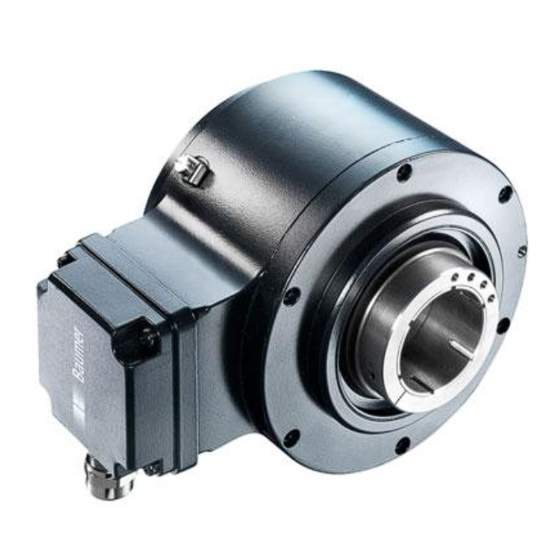
- Page 1 Montage- und Betriebsanleitung Mounting and operating instructions Option M: redundant HOG 161 Inkrementaler Drehgeber Incremental encoder...
-
Page 2: Table Of Contents
Montage / Mounting Inhaltsverzeichnis Inhaltsverzeichnis Allgemeine Hinweise ................................Betrieb in explosionsgefährdeten Bereichen ....................Sicherheitshinweise ................................Vorbereitung .................................... Lieferumfang ................................Zur Montage erforderlich (nicht im Lieferumfang enthalten) ............. Erforderliches Werkzeug (nicht im Lieferumfang enthalten) ............. Montage ..................................... Schritt 1 ..................................Schritt 2 .................................. - Page 3 Montage / Mounting Table of contents Table of contents General notes ..................................Operation in potentially explosive environments ................... Security indications ................................Preparation ....................................Scope of delivery ..............................Required for mounting (not included in scope of delivery) ..............Required tools (not included in scope of delivery) ..................
-
Page 4: Allgemeine Hinweise
Information Empfehlung für die Gerätehandhabung Der inkrementale Drehgeber HOG 161 ist ein opto-elektronisches Prä zi sionsmessgerät, das mit Sorgfalt nur von technisch qualifiziertem Per sonal gehandhabt werden darf. Die zu erwartende Lebensdauer des Gerätes hängt von den Kugellagern ab, die mit einer Dauerschmierung ausgestattet sind. -
Page 5: General Notes
Information Recommendation for device handling The incremental encoder HOG 161 is an opto electro nic precision measurement device which must be handled with care by skilled personnel only. The expected service life of the device depends on the ball bearings, which are equipped with a permanent lubrication. -
Page 6: Betrieb In Explosionsgefährdeten Bereichen
Betrieb in explosionsgefährdeten Bereichen Betrieb in explosionsgefährdeten Bereichen Das Gerät entspricht der Richtlinie 2014/34/EU für explosionsgefährdete Bereiche. Der Einsatz ist gemäß den Gerätekategorien 3 G (Ex-Atmosphäre Gas) und 3 D (Ex-Atmo- sphäre Staub) zulässig. Gerätekategorie 3 G: - Ex-Kennzeichnung: II 3 G Ex nA IIC T4 Gc - Normenkonformität: EN 60079-0:2012 + A11:2013 EN 60079-15:2010... -
Page 7: Operation In Potentially Explosive Environments
Operation in potentially explosive environments Operation in potentially explosive environments The device complies with the directive 2014/34/EU for potentionally explosive atmospheres. It can be used in accordance with equipment categories 3 G (explosive gas atmosphere) and 3 D (explosive dust atmosphere). Equipment category 3 G: - Ex labeling: II 3 G Ex nA IIC T4 Gc - Conforms to standard:... -
Page 8: Sicherheitshinweise
Sicherheitshinweise Sicherheitshinweise Verletzungsgefahr durch rotierende Wellen Haare und Kleidungsstücke können von rotierenden Wellen erfasst werden. • Vor allen Arbeiten alle Betriebsspannungen ausschalten und Maschinen stillsetzen. Zerstörungsgefahr durch elektrostatische Aufladung Die elektronischen Bauteile im Gerät sind empfindlich gegen hohe Spannungen. • Steckkontakte und elektronische Komponenten nicht berühren. •... -
Page 9: Security Indications
Security indications Security indications Risk of injury due to rotating shafts Hair and clothes may become tangled in rotating shafts. • Before all work switch off all voltage supplies and ensure machinery is stationary. Risk of destruction due to electrostatic charge Electronic parts contained in the device are sensitive to high voltages. -
Page 10: Vorbereitung
Anschlussplatine, siehe Abschnitt 5.9 und 7.3. Connecting board, see section 5.9 and 7.3. Torx-/Schlitzschraube M3x10 mm Torx/slotted screw M3x10 mm D-SUB Stecker D-SUB connector (male) am Gerätegehäuse on the device housing Option M: Redundante Abtastung HOG 161 Option M: Redundant sensing HOG 161 MB090T1 - 11055700 Baumer_HOG161-HOG161M-T1_II_DE-EN (20A1) -
Page 11: Zur Montage Erforderlich (Nicht Im Lieferumfang Enthalten)
Vorbereitung / Preparation Zur Montage erforderlich Required for mounting (nicht im Lieferumfang enthalten) (not included in scope of delivery) 18b 18c 3x 3x Drehmomentstütze, als Zubehör erhältlich: Torque arm, available as accessory: Bestellnummer Länge L, Version Order number Length L, version 11043628 67...70 mm, Standard 11043628 67...70 mm, standard... -
Page 12: Erforderliches Werkzeug (Nicht Im Lieferumfang Enthalten)
Vorbereitung / Preparation Erforderliches Werkzeug Required tools (nicht im Lieferumfang enthalten) (not included in scope of delivery) 3 oder 4 mm 3 or 4 mm 1,6x8 mm 1.6x8 mm 10 (2x) und 22 mm 10 (2x) and 22 mm TX 10, TX 20 TX 10, TX 20 Werkzeugset als Zubehör erhältlich: Tool kit available as accessory:... -
Page 13: Montage
Montage / Mounting Montage Mounting In den Bildern am Beispiel des Typs Pictures showing type HOG 161 as exam- HOG 161. Gleiche Montageschritte bei ple. Same mounting steps for redundant redundanter Version HOG 161 M. version HOG 161 M. Schritt 1... -
Page 14: Schritt 3
Montage / Mounting Schritt 3 Step 3 10 mm 1.6x8 mm * Siehe Seite 7 oder 8 See page 7 or 8 Antriebswelle einfetten. Lubricate drive shaft. Die Antriebswelle sollte einen The drive shaft should have as less möglichst kleinen Rundlauffehler runout as possible because this can aufweisen, da dieser zu einem otherwise result in an angle error, see... -
Page 15: Schritt 4 - Drehmomentstütze
Montage / Mounting Schritt 4 - Drehmomentstütze Step 4 - Torque arm Die Montage der Drehmomentstütze The torque arm should be mounted sollte spielfrei erfolgen. Ein Spiel von free from clearance. A play of just beispielsweise ±0,03 mm entspricht ±0.03 mm, results in a runout of the einem Rundlauffehler des Gerätes von device of 0.06 mm. -
Page 16: Hinweis Zur Vermeidung Von Messfehlern
Montage / Mounting Hinweis zur Vermeidung von Messfeh- How to prevent measurement errors lern Für einen einwandfreien Betrieb des To ensure that the device operates cor- Gerätes ist eine korrekte Montage, ins- rectly, it is necessary to mount it accu- besondere auch der Drehmomentstütze, rately as described in section 5.1 to 5.4, notwendig, wie beschrieben in Abschnitt... -
Page 17: Schritt 5
Montage / Mounting Schritt 5 Step 5 3 mm (ød1 ≤65 mm) 4 mm (ød1 >65 mm) Anzugsmoment Tightening torque = 2...3 Nm Schritt 6 - Klemmenkasten Step 6 - Terminal box TX 20 12 * 22 mm * Siehe Seite 7 See page 7 MB090T1 - 11055700 Baumer_HOG161-HOG161M-T1_II_DE-EN (20A1) -
Page 18: Schritt 7 Und 8 - Klemmenkasten
Montage / Mounting Schritt 7 und 8 - Klemmenkasten Step 7 and 8 - Terminal box TX 10 12 * ø5...13 mm * Siehe Seite 7 oder 8 See page 7 or 8 Zur Gewährleistung der angegebenen To ensure the specified protection of Schutzart sind nur geeignete Kabel- the device the correct cable diameter durchmesser zu verwenden. -
Page 19: Schritt 9 - Klemmenkasten
Montage / Mounting Schritt 9 - Klemmenkasten Step 9 - Terminal box Ansicht X siehe Abschnitt 7.3. Kabelschirm View X Cable shield see section 7.3. 5.10 Schritt 10 - Klemmenkasten 5.10 Step 10 - Terminal box D-SUB Buchse zum Anschluss an Gerätegehäuse TX 10 siehe Abschnitt 5.11. -
Page 20: Schritt 11 - Klemmenkasten
Montage / Mounting 5.11 Schritt 11 - Klemmenkasten 5.11 Step 11 - Terminal box Anzugsmoment Tightening torque = 2...3 Nm TX 20 Großer, um 180° wendbarer Klemmenkasten. Big terminal box, turn by 180°. Anzugsmoment Tightening torque = 2...3 Nm TX 20 * Siehe Seite 7 See page 7 Vor der Montage des Klemmenkasten-... -
Page 21: Montagehinweis
Montage / Mounting 5.12 Montagehinweis 5.12 Mounting instruction Wir empfehlen, das Gerät so zu It is recommended to mount the device montieren, dass der Kabelanschluss with cable connection facing down- keinem direkten Wassereintritt ward and being not exposed to water. ausgesetzt ist. -
Page 22: Abmessungen
Abmessungen / Dimensions Abmessungen Dimensions Hohlwellendurchmesser 38...46 mm Hollow shaft diameter 38...46 mm (74106) (74106) Option M: redundant ød1 ød2 60.5 Drehrichtung positiv 66.5 Positive rotating direction Hohlwellendurchmesser 48...75 mm Hollow shaft diameter 48...75 mm (74103, 74410, 74413) (74103, 74410, 74413) Option M: redundant ød1 ød2... -
Page 23: Elektrischer Anschluss
Elektrischer Anschluss / Electrical connection Elektrischer Anschluss Electrical connection Beschreibung der Anschlüsse Terminal significance Betriebsspannung Voltage supply Masseanschluss 0V ( ) Ground Erdungsanschluss (Gehäuse) Earth ground (housing) Ausgangssignal Kanal 1 Output signal channel 1 Ausgangssignal Kanal 1 invertiert Output signal channel 1 inverted Ausgangssignal Kanal 2 (90°... -
Page 24: Klemmenbelegung
Elektrischer Anschluss / Electrical connection Klemmenbelegung Terminal assignment 7.3.1 D … 7.3.1 D … Max. 1,5 mm Ansicht X Max. AWG 16 Anschlussklemmen, siehe Abschnitt 5.9. View X Connecting terminal, see section 5.9. 0V ( ) Zwischen besteht keine Verbindung. There is no connection between 7.3.2 DN …... -
Page 25: Sensorkabel Hek 8 (Zubehör)
Elektrischer Anschluss / Electrical connection Sensorkabel HEK 8 (Zubehör) Sensor cable HEK 8 (accessory) Es wird empfohlen, das Baumer Hübner Baumer Hübner sensor cable HEK 8 is Sensorkabel HEK 8 zu verwenden oder recommended. As a substitute a shielded ersatzweise ein geschirmtes, paarig ver- twisted pair cable should be used. -
Page 26: Demontage
Demontage / Dismounting Demontage Dismounting In den Bildern am Beispiel des Typs Pictures showing type HOG 161 as exam- HOG 161. Gleiche Demontageschritte bei ple. Same dismounting steps for redun- redundanter Version HOG 161 M. dant version HOG 161 M. Schritt 1 und 2 Step 1 and 2 Elektrische Verbindung trennen. -
Page 27: Schritt 3
Demontage / Dismounting Schritt 3 Step 3 3 mm (ød1 ≤65 mm) 4 mm (ød1 >65 mm) 10 mm 1.6x8 mm Schritt 4 Step 4 * Siehe Seite 7 oder 8 See page 7 or 8 MB090T1 - 11055700 Baumer_HOG161-HOG161M-T1_II_DE-EN (20A1) -
Page 28: Technische Daten
Technische Daten Technische Daten Technische Daten - elektrisch • Betriebsspannung: 9...30 VDC (HTL) 9...26 VDC (TTL - Version R) 5 VDC ±5 % (TTL) • Betriebsstrom ohne Last: ≤100 mA • Impulse pro Umdrehung: 250...2500 (je nach Bestellung) • Phasenverschiebung: 90°... -
Page 29: Technical Data
Technical data Technical data Technical data - electrical ratings • Voltage supply: 9...30 VDC (HTL) 9...26 VDC (TTL - version R) 5 VDC ±5 % (TTL) • Consumption w/o load: ≤100 mA • Pulses per revolution: 250...2500 (as ordered) • Phase shift: 90° ±20° •... -
Page 30: Zubehör
Zubehör / Accessories Zubehör Accessories • Drehmomentstütze Größe M6: • Torque arm size M6: Bestellnummer siehe Order number see Abschnitt 4.2 section 4.2 • Montageset für Drehmoment- • Mounting kit for torque arm stütze Größe M6 und Erdungs- size M6 and earthing strap: band: Bestellnummer 11077197 Order number 11077197 •... -
Page 31: Eu-Konformitätserklärung
Signature/nom/fonction Baumer_HOGx_OGx_POGx_FOGx_HMI_DE-EN-FR_CoC_81201236.docm/kwe Baumer Hübner GmbH P.O. Box 126943 ∙ D-10609 Berlin ∙ Max-Dohrn-Str. 2+4 ∙ D-10589 Berlin Phone +49 (0)30 69003-0 ∙ Fax +49 (0)30 69003-104 ∙ info@baumerhuebner.com ∙ www.baumer.com Sitz der Gesellschaft / Registered Office: Berlin, Germany ∙ Geschäftsführer / Managing Director: Dr. Oliver Vietze, Dr. Johann Pohany Handelsregister / Commercial Registry: AG Charlottenburg HRB 96409 ∙... - Page 32 Baumer Hübner GmbH P.O. Box 12 69 43 · 10609 Berlin, Germany Phone: +49 (0)30/69003-0 · Fax: +49 (0)30/69003-104 info@baumerhuebner.com · www.baumer.com/motion Version: 74103, 74106, 74410, 74413 MB090T1 - 11055700 Baumer_HOG161-HOG161M-T1_II_DE-EN (20A1-24.02.2020)
Need help?
Do you have a question about the HOG 161 and is the answer not in the manual?
Questions and answers