
Related Manuals for Daikin EKMBPP1


Summary of Contents for Daikin EKMBPP1
- Page 1 Installation manual Modbus adapter Installation manual English EKMBPP1 Modbus adapter...
-
Page 2: Table Of Contents
6.3.1 Modbus address range ............20 6.3.2 Modbus registers ..............21 6.3.3 Modbus master timeout ............22 6.3.4 Terminating resistor settings........... 23 6.4 Control functions ................23 6.4.1 Unit control................23 6.4.2 Control update mode .............. 24 Installation manual EKMBPP1 Modbus adapter 4P720139-1B – 2023.09... -
Page 3: About This Document
Authorised installers About the documentation The instructions delivered with the kit are intended to guide you through the installation of the EKMBPP1 adapter into a KRP1BC101 installation box and through the connection and configuration of the EKMBPP1 adapter. Read this installation manual prior to use and keep it for future reference. -
Page 4: Specific Installer Safety Instructions
▪ Format: paper (supplied in the kit) Latest revisions of the supplied documentation may be available on the regional Daikin website or via your dealer. The original instructions are written in English. All other languages are translations of the original instructions. - Page 5 (Safety Extra Low Voltage) power supply, all external wiring and electrically attached devices MUST be double insulated to prevent access by non-qualified persons. When this is not possible, the EKMBPP1 MUST be powered by a SELV power supply. DANGER: RISK OF ELECTROCUTION...
- Page 6 2 Specific installer safety instructions WARNING When applying this Modbus adapter (EKMBPP1), the installation requirements described in the indoor and outdoor unit installation manuals of the system to which this Modbus adapter is connected, including any countermeasures, remain applicable. For systems NOT using R32 refrigerant, this Modbus adapter can be the only (and main) remote controller connected.
-
Page 7: About The Kit
3 About the kit About the kit The EKMBPP1 kit is a Modbus interface to monitor and control the VRV and Sky Air ranges of air conditioners, as well as the VAM and VKM ventilation units. The interface is compatible with units that have a P1P2 remote controller connection, allowing control of up to 16 units in a single group. -
Page 8: Basic Parameters
Make sure the indoor unit is compatible with the kit. For an exhaustive list of compatible models and the corresponding required installation box, see the compatibility matrix or data book of the indoor unit or the general catalogue. Installation manual EKMBPP1 Modbus adapter 4P720139-1B – 2023.09... -
Page 9: About The Box
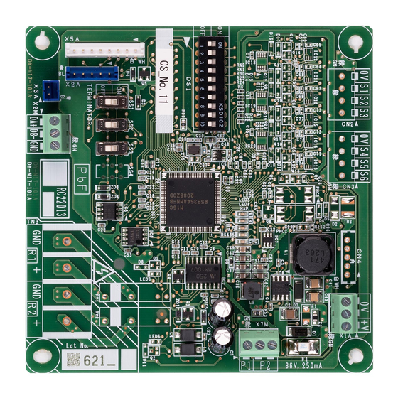
4 About the box About the box To unpack the adapter a EKMBPP1 Modbus adapter PCB b Installation manual c PCB clamp (4×) d Cable gland and locknut (M20×1.5) e Wire harness for power supply (2×) EKMBPP1 Installation manual Modbus adapter... -
Page 10: Installation
Preparing the installation site The EKMBPP1 is an option PCB. The installation procedure and installation location of the PCB vary depending on the unit(s). See the installer reference guide of the indoor unit for more information. -
Page 11: To Install The Modbus Adapter
"5.4.1 Overview of electrical connections" [4 14]. To install the Modbus adapter Install the EKMBPP1 inside the indoor unit, in the space foreseen for the option PCB. See the installer reference guide of the indoor unit for more information. In case of KRP1BC101 installation box, follow the procedure in "5.3.1... - Page 12 ▪ Connect the wiring to the PCB. For more information, also see "5.4 Connecting the electrical wiring" [4 13]. 6 Install the PCB with the PCB clamps into the KRP1BC101 installation box. Make sure the PCB is oriented in the right direction: Installation manual EKMBPP1 Modbus adapter 4P720139-1B – 2023.09...
-
Page 13: To Install The Modbus Adapter Pcb With Field Supplied Casing
To install the Modbus adapter PCB with field supplied casing In case of field supplied casing, EKMBPP1 MUST be installed using: ▪ A double insulated plastic box, or ▪ A metal box which is earthed properly to be compliant to the applicable electrical safety norm. -
Page 14: Overview Of Electrical Connections
(Safety Extra Low Voltage) power supply, all external wiring and electrically attached devices MUST be double insulated to prevent access by non-qualified persons. When this is not possible, the EKMBPP1 MUST be powered by a SELV power supply. 5.4.1 Overview of electrical connections... -
Page 15: To Connect The Power Supply
To connect the power supply Power supplied by the indoor unit Power for EKMBPP1 can be supplied from the indoor unit PCB. For Sky Air units, connect to X35A on the indoor unit PCB. For VRV units, connect to either X18A or X35A on the indoor unit PCB. -
Page 16: To Connect The P1P2 Wiring
NOT matter. 1 Connect indoor unit terminals P1 and P2 to the EKMBPP1 terminals P1 and P2 on the X7M connector. 2 Ensure strain relief by routing the cable along the cable path suggested in the indoor unit installation manual. -
Page 17: To Connect The Rs485 Wiring
▪ Terminal DB(-) MUST be connected to all other DB(-) terminals, on every EKMBPP1 kit. ▪ The common terminal ground (GND) MUST be connected together, on every EKMBPP1 kit. When using a shielded cable, the shield can be used for this purpose. DB- DA+... -
Page 18: Configuration
For information on the terminating resistance, see "6.3.4 Terminating resistor settings" [4 23]. Configuration Status LEDs The EKMBPP1 has 5 LEDs that display information about the current status. See "3.1 Components" [4 7] for the location of the LEDs on the PCB. Description... - Page 19 LED 2 Red LED LED ON LED ON LED OFF a Power-up sequence b No error c P1P2 search mode d Unit error e U5 error (AC unit is missing) f RS485 communicaton timeout EKMBPP1 Installation manual Modbus adapter 4P720139-1B – 2023.09...
-
Page 20: P1P2 Communication
6 Configuration P1P2 communication The EKMBPP1 enters P1P2 search mode in three cases: 1 When the adapter is powered on, it enters the P1P2 search mode. The adapter cycles between Sub mode and Main mode. 2 If the adapter is in Main mode, it enters the P1P2 search mode when a communication error occurs with all connected indoor units. -
Page 21: Modbus Registers
6 Configuration 6.3.2 Modbus registers The EKMBPP1 supports 2 types of registers: holding registers and input registers. Register type Access Function(s) Holding register Read/Write Control and command, readback and monitoring Input register Read-only Readback and monitoring The input registers are used to access all analogue and digital values. -
Page 22: Modbus Master Timeout
6.3.3 Modbus master timeout The EKMBPP1 can be configured to operate with an optional Modbus master timeout. When no holding register occurs for a period of 120 seconds, a timeout event occurs: all units switch on with their current settings and the status LEDs indicate an RS485 communication timeout. -
Page 23: Terminating Resistor Settings
Control functions 6.4.1 Unit control Holding registers allow the EKMBPP1 to control the functions of Sky Air and VRV air conditioning units that are available from the standard remote controller. For more information about the types of registers and possible data types, see "6.3.2 Modbus registers"... -
Page 24: Control Update Mode
[4 23]) has a corresponding update register. The update register determines how the control commands update the unit and whether the corresponding remote controller button(s) are locked or unlocked. The following update modes are available: Installation manual EKMBPP1 Modbus adapter 4P720139-1B – 2023.09... - Page 25 ▪ 0: LastTouch H0010 ▪ 1: Central 40012 Setpoint Update H0011 ▪ 2: Local 40013 Fanspeed Update H0012 ▪ 3: OnChange 40014 Mode Update H0013 40015 Airflow direction Update H0014 40016 ON/OFF Update H0015 EKMBPP1 Installation manual Modbus adapter 4P720139-1B – 2023.09...
-
Page 26: Control Limiting
▪ 4: Medium Low ▪ 8: Medium ▪ 16: Medium High ▪ 32: High 40024 Mode Inhibit Inhibit value: H0023 ▪ 1: Auto ▪ 2: Heating ▪ 4: Fan ▪ 8: Cooling ▪ 16: Dry Installation manual EKMBPP1 Modbus adapter 4P720139-1B – 2023.09... -
Page 27: Vam-Specific Control
VAM-specific control In addition to the standard unit control functions (see "6.4.1 Unit control" [4 23]), the EKMBPP1 can be used to control functions specific to VAM and VKM units. The following holding registers are available: Holding register Address Name... -
Page 28: Readback Data
Error Code 0~65535 ▪ 255: No error I0022 ▪ Other values: error code from first unit in error 30024 Return Air Average °C × 100 Average of all unit return air I0023 temperatures Installation manual EKMBPP1 Modbus adapter 4P720139-1B – 2023.09... -
Page 29: Unit Readback
Unit return air sensor I0123 I1623 value … Filter Alarm ▪ 0: No alarm I0124 I1624 ▪ 1: Filter alarm … Thermo On ▪ 0: Idle/Fan I0130 I1630 ▪ 1: Heating ▪ 2: Cooling EKMBPP1 Installation manual Modbus adapter 4P720139-1B – 2023.09... -
Page 30: Error Codes
Coil outlet temperature I0132 I1632 Values are only available when the EKMBPP1 is operating in P1P2 Main mode. The following table outlines the logic to determine the register addresses for every unit (1~16). The second and third digits indicate the indoor unit number. -
Page 31: Smart Grid
In case the air conditioning system is connected to a third-party device able to provide Smart Grid requests (e.g. a power meter connected to the grid), the EKMBPP1 is able to receive this information and use it in order to execute Smart Grid requests to control the power consumption of the system. - Page 32 Only 1 Modbus master is allowed. If the system is under control by a Smart Grid provider, this means it cannot be controlled by a BMS (building management system) at the same time and vice versa. Installation manual EKMBPP1 Modbus adapter 4P720139-1B – 2023.09...
-
Page 33: Software Update
Software update To perform software updates, a PC cable (EKPCCAB4) and the Updater Tool are required. Connect the EKMBPP1 to a PC with the PC cable. The latest version of the Updater Tool can be downloaded from the Daikin Business Portal. -
Page 34: Disposal
By ensuring this product is disposed of correctly, you will help to prevent potential negative consequences for the environment and human health. For more information, contact your installer or local authority. Installation manual EKMBPP1 Modbus adapter 4P720139-1B – 2023.09... -
Page 35: Technical Data
Not mounted in switch box Wiring depending on model Indoor unit INDOOR HAP, LED* Light-emitting diode (service monitor is green) SS* Slide switch X*A, X*M, CN*, TN* Connector X2A Connector for SW Updater Tool EKMBPP1 Installation manual Modbus adapter 4P720139-1B – 2023.09... -
Page 36: Appendix
5 6 7 8 9 10 1 2 3 4 5 6 7 8 9 10 1 2 3 4 5 6 7 8 9 10 1 2 3 4 5 6 7 8 9 10 Installation manual EKMBPP1 Modbus adapter 4P720139-1B – 2023.09... - Page 40 4P720139-1 B 0000000- 4P720139-1B 2023.09 Verantwortung für Energie und Umwelt...
Need help?
Do you have a question about the EKMBPP1 and is the answer not in the manual?
Questions and answers