Advertisement
Advertisement
Table of Contents

Related Manuals for Daikin BRP072B42


Summary of Contents for Daikin BRP072B42
- Page 1 Installation Manual Wireless LAN Connecting Adapter [ BRP072B42 ]...
- Page 3 Installation Manual Wireless LAN Connecting Adapter [ BRP072B42 ] Website: http://www.daikinthai.com/wlan3/modbus • For details on specifications, setting methods, FAQ, and the latest version of this manual, see our website. Accessories Accessories Check if the following accessories are included in your package.
-
Page 4: Safety Precautions
Safety precautions Safety precautions • The following describes the meanings of pictorial symbols used in this installation manual. Give this installation manual to the customer when installation is completed. • To conduct a test run of the air conditioner, complete according to the installation manual for the air conditioner unit. -
Page 5: When Using
Safety precautions Safety precautions WARNING Situations which could result in death or serious injury. When using: Do not disassemble, modify, or repair. (Could cause fire, electric shock or injury.) Do not handle the Wireless LAN connecting adapter with wet hands. (Could cause electric shock or fire.) ... - Page 6 Safety precautions Safety precautions CAUTION Situations which could result in damage or physical injury. When installing: Do not install where flammable gas leaks can occur. (Could cause fire.) Grip the connector when disconnecting the wire harness assembly from the outlet. (Otherwise fire or electric shock can occur.) When using: ...
-
Page 7: Main Components
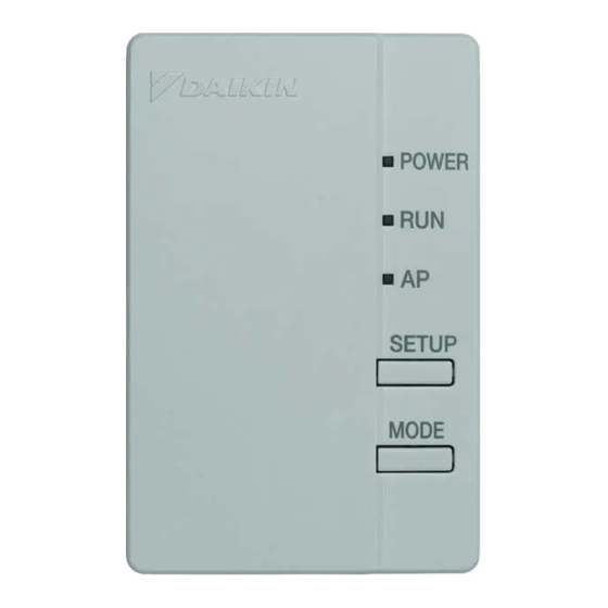
(Wireless LAN access point). Use when connecting to a router (Wireless LAN access point). AP lamp* MODE button* POWER button* * No operation for BRP072B42 model. Installation type Wireless LAN connecting adapter (External) Installation type Wireless LAN connecting adapter (the product is inside the indoor unit) -
Page 8: Installation
Installation Installation Installation Work Always turn off the power supply when installing. WARNING (Touching the electrical parts could cause an electric shock.) The main switch of the installation is at the outdoor unit. The steps to be followed depend on the installation type: type = External, type = Internal. - Page 9 Installation Installation Installation Work In the case of • Some models already have the wire harness assembly installed in the indoor unit. In such a case, please proceed with the installation as below. Remove the upper front panel from the indoor unit and open the door, grab the wire harness assembly with your fingers and pull it out, then remove the binding band and pull the insulation tube off the wire harness assembly.
- Page 10 Installation Installation Installation Work Attach wire harness assembly to the Wireless LAN connecting adapter. (For both Attach the wire harness assembly connector (white). • Fasten the wire harness assembly to the notch in the Wireless LAN connecting adapter case (lower). Connect the connector to the same color.
- Page 11 Installation Installation Installation Work Installation of Wireless LAN connecting adapter. In the case of Install the Wireless LAN connecting adapter outside the indoor unit. There are two ways of installation A1 and A2. TYPE A1 Position of the Wireless LAN connecting adapter on the wall/surface is fixed by screws. In this case double face tapes located in accessory set are not necessary to fix the holder.
- Page 12 Installation Installation Installation Work TYPE A2 Position of the Wireless LAN connecting adapter on the wall/surface is fixed by double face tapes. In this case screws located in accessory set are not necessary to fix the holder. 1. Attach two double face tapes located in accessory set to the back side of holder as shown below.
-
Page 13: Functionality Check
Installation Installation Installation Work Functionality Check In the case of Turn on the main power supply and check that the [RUN] lamp of the Wireless LAN connecting adapter blinks. In the case of Turn on the power supply, wait until the initialization is completed (the lower panel is in the closed position). - Page 14 Configuration Configuration Wireless Connection Set ing Section The customer is responsible for providing the following: • Additional devices such as smartphones, tablets, desktop PCs, laptops or other devices that can be used as the interface between the Home gateway controller and the Wireless LAN connecting adapter •...
- Page 15 Configuration Configuration Wireless Connection Setting Sec ion Push the [SETUP] button on the Wireless LAN connecting adapter for approximately 2 seconds. • The [RUN] lamp on the Wireless LAN connecting adapter blinks more quickly. When the Wireless LAN connecting adapter and the router (Wireless LAN access point) are connected, this lamp lights.
-
Page 16: Troubleshooting
Troubleshooting Troubleshooting The following table provides brief descriptions of how to handle trouble or uncertainties when you install the Wireless LAN connecting adapter or make connection settings. Refer to the FAQ on our website for more details. When this happens Explanation and where to check None of the LEDs light. - Page 17 MEMO...
- Page 18 MEMO...
- Page 20 This telecommunication equipment is in compliance with NTC requirements. Complies with IMDA Standards DA107930 4P518835-1B M17N103A...
Need help?
Do you have a question about the BRP072B42 and is the answer not in the manual?
Questions and answers