Table of Contents
Advertisement
Quick Links
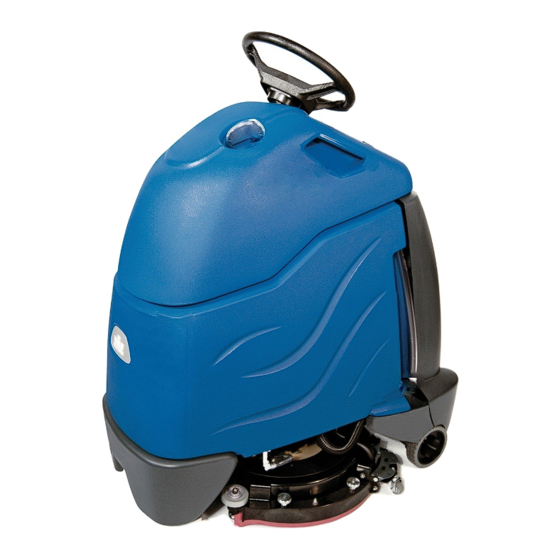
Chariot 2 iScrub 20
Operating Instructions (ENG)
MODELS:
CS20
1.006-125.0
CSC20
1.006-133.0
.CSX20
1006-137.0
CSXC20
1.006-138.0
CS22SP
1.006-130.0
CSC22SP
1.006-134.0
CSXM20
1.006-170.0
CSXCM20
1.006-171.0
CSM22SP
1.006-172.0
CSCM22SP
1.006-173.0
From Serial Number (Ref No. 1*)
* See Serial Number page in Spare
Parts List or call manufacturer.
86398220-G 08/01/17
Scrubber
CSXBCM20
1.006-181.0
CSXBC20
1.006-182.0
CSXBM20
1.006-183.0
CSXB20
1.006-184.0
Advertisement
Chapters
Table of Contents
Troubleshooting

Subscribe to Our Youtube Channel
Related Manuals for Kärcher Windsor Chariot 2 iScrub 20


Summary of Contents for Kärcher Windsor Chariot 2 iScrub 20
- Page 1 Chariot 2 iScrub 20 Scrubber Operating Instructions (ENG) MODELS: CS20 CSXBCM20 1.006-125.0 1.006-181.0 CSC20 CSXBC20 1.006-133.0 1.006-182.0 .CSX20 CSXBM20 1006-137.0 1.006-183.0 CSXC20 CSXB20 1.006-138.0 1.006-184.0 CS22SP 1.006-130.0 CSC22SP 1.006-134.0 CSXM20 1.006-170.0 CSXCM20 1.006-171.0 CSM22SP 1.006-172.0 CSCM22SP 1.006-173.0 From Serial Number (Ref No. 1*) * See Serial Number page in Spare Parts List or call manufacturer.
-
Page 2: Machine Data Label
Machine Data Label Overview The Chariot Scrubber is a battery powered, stand-on, hard floor scrubber intended for commercial use. The appliance applies a cleaning solution onto a hard floor, scrubs the floor with brush or pad, and then vacuums the soiled water back into the recovery tank. -
Page 3: Table Of Contents
Table of Contents Vacuum & Float Shutoff .....56 Machine Data Label ......2 Overview . -
Page 4: How To Use This Manual
How To Use This Manual This manual contains the following sections: The SAFETY section contains important information regarding hazardous or unsafe practices of the • HOW TO USE THIS MANUAL machine. Levels of hazards are identified that could • SAFETY result in product damage, personal injury, or severe •... -
Page 5: Safety
Safety IMPORTANT SAFETY INSTRUCTIONS When using this machine, basic precaution must always be followed, including the following: READ ALL INSTRUCTIONS BEFORE USING THIS MACHINE. To reduce the risk of fire, electric shock, or injury: Use only indoors. Do not use outdoors or expose to rain. Use only as described in this manual. - Page 6 Safety MESURES DE SÉCURITÉ IMPORTANTES Lors de l'utilisation d'un appareil à batteries, il est nécessaire de respecter systématiquement des mesures de sécurité de base, comme suit : PRENEZ NOTE DE TOUTES CES MESURES AVANT D'UTILISER CETTE MACHINE. Pour réduire les risques d'incendie, de chocs électriques, ou de blessures : N'utiliser cette machine qu'en intérieur.
-
Page 7: Hazard Intensity Level
Safety The following symbols are used throughout this guide as indicated in their descriptions: HAZARD INTENSITY LEVEL There are three levels of hazard intensity identified by signal words -WARNING and CAUTION and FOR SAFETY. The level of hazard intensity is determined by the following definitions: WARNING - Hazards or unsafe practices which COULD result in severe personal injury or death. - Page 8 Safety Les symboles ci-dessous sont utilisés à travers ce manuel comme illustré dans leurs descriptions : DEGRÉS DE RISQUES EN CAS DE DANGER Il existe trois degrés de risques identifiés par les termes signalétiques -AVERTISSEMENT et ATTENTION et POUR VOTRE SÉCURITÉ. Le degré de risque est défini de la manière suivante: AVERTISSEMENT - Dangers ou méthodes dangereuses qui POURRAIENT provoquer de graves blessures ou entraîner la mort.
-
Page 9: Safety Label Locations
Safety SAFETY LABEL LOCATIONS These drawings indicate the location of safety labels on the machine. If at any time the labels become illegible, promptly replace them. EMPLACEMENT DE L'ÉTIQUETTE DE SÉCURITÉ REMARQUE : Ces dessins indiquent l'emplacement des étiquettes de sécurité sur la machine. Si, à tout moment, les étiquettes deviennent illisibles, contactez votre représentant autorisé... -
Page 10: Operations
Operations Technical Specifications ITEM DIMENSION/CAPACITY Nominal Power-Disk 1080 W Nominal Power-Orbital 936 W Nominal Power-Cylindrical 1512 W Rated Voltage 36 Volts DC Rated Amperage -Disk 30 amps Rated Amperage -Orbital 26 amps Rated Amperage -Cylindrical 42 amps Batteries 3 X12 Volt 130 AH @ 20 hr. rate Battery Compartment Dimensions 20-1/2 in. - Page 11 Operations ITEM MEASURE Height 51.8 in (1316mm) Length 44.0 in (1118mm) Width without squeegee - Disk / Orbital 23.4 in (594mm) Width without squeegee - Cylindrical 25.4 in (645mm) Width of squeegee - Disk / Orbital 27.2 in (691mm) Width of squeegee - Cylindrical 29.3 in (744mm) Width of scrub path - Disk / Orbital 20 in (508mm)
-
Page 12: How This Machine Works
Operations How This Machine Works The function of the recovery system is to vacuum the The Chariot® is a battery powered, self-propelled, hard soiled water back into the recovery tank. The recovery floor scrubber intended for commercial use. The system consists of the squeegee, vacuum motor, float appliance applies a cleaning solution onto a hard floor, ball, recovery tank. -
Page 13: Components
Operations Deluxe Disk & Cylindrical Cylindrical Components 7. Recovery Sight Dome 1. Drive Control 8. Recovery Drain Hose 2. Scrub Controls 9. Scrub Deck Skirt 3. Control Console 10. Solution Cover 4. Pedal Platform 11. Solution Drain Hose/Solution Level Indicator 5. -
Page 14: Drive Controls
Operations Drive Controls 86398220 Operators Manual - Chariot-2 iScrub 20... - Page 15 Operations 2. EMERGENCY STOP/BRAKE SWITCH This safety feature is designed to cut all power to 1. Key Switch the machine at any time and apply parking brake. 2. Emergency Stop/Brake Switch To shut the machine power off, push the Emergency Stop Switch, this will also engage the 3.
- Page 16 Operations 4. THROTTLE PEDAL Controls the speed of the vehicle within the speed control setting selected. Pressing the pedal causes the machine to travel in the direction selected by the Directional Control Switch. To increase speed, increase pressure on the pedal. To decrease speed, decrease pressure on the pedal.
- Page 17 Operations 8. BATTERY DISCHARGE INDICATOR Indicates the charge level of the batteries. The indicator will be illuminated if the batteries have a sufficient charge. A slow, continuous flash indicates the batteries require charging. The Battery Lockout function will activate when the batteries are low. Once active, the LED status indicator will begin to flash slowly and the controller will inhibit the scrub motor and water solenoid.
-
Page 18: Scrub Controls
Operations Scrub Controls LABEL WITH FINISH REMOVAL MODE. LABEL WITH CHEMICAL METERING OPTION. 1. FUNCTION MODE SWITCH The first two positions are for transport only. See drive controls section. Light cleaning This mode is used for light cleaning. In this mode the machine will propel at fast speed. The ‘floating’... - Page 19 Operations Vacuum only mode This mode is used for picking up solution only. The brush and water will both be up and off. In this mode the machine will propel at fast speed. The squeegee is lowered and the vacuum will come on.
-
Page 20: Scrub Controls - Squeegee
Operations Scrub Controls - Squeegee DISK / ORBITAL 1. Squeegee Latch 2. Squeegee Hose and Tube 3. Squeegee Wheels (3) 4. Double Scrub Support Cable 5. Double Scrub Cable Hook 86398220 Operators Manual - Chariot-2 iScrub 20... - Page 21 Operations 1. Squeegee Latch The squeegee latch holds the squeegee in place. 2. Squeegee Hose and Tube The squeegee hose and tube carry the recovered solution to the recovery tank. 3. Squeegee Wheels The squeegee wheels support the squeegee at the correct height and angle to automatically obtain optimum suction.
-
Page 22: Scrub Controls - Solution Flow Rate
Operations Scrub Controls - Solution Flow Rate DISK / ORBITAL 1. Shut-off Valve The shut-off valve controls the rate at which solution is delivered to the scrub deck. 86398220 Operators Manual - Chariot-2 iScrub 20... -
Page 23: Pre-Run Machine Inspection
Operations 3. Measure the chemical into the solution tank. Liquid Machine Operation chemicals should be added to the solution tank after filling with water. Dry chemicals should be Pre-Run Machine Inspection thoroughly mixed before being added into solution Do a pre-run inspection to find possible problems that tank. -
Page 24: Normal Scrubbing
Operations 3. Measure the chemical into the solution tank. Liquid To Begin Scrubbing chemicals should be added to the solution tank after filling with water. Dry chemicals should be thoroughly mixed before being added into solution tank. Commercially available, high alkaline floor When operating the machine around people, pay cleaners, are suitable for use in the solution close attention for unexpected movement. -
Page 25: Double Scrub
Operations To Stop Scrubbing 1. Rotate the function knob to either transport posi- tion. The brush motor and vacuum will stop and the scrub deck will rise to the park position, after a pre- programmed delay. 2. Allow the throttle pedal to return to neutral. 3. -
Page 26: Finish Removal (On Select Orbital Models)
Operations Finish Removal (on select orbital models) It may be desirable to remove layers of floor finish from a floor. Use the chemical free floor finish removal mode for best results. 1. Install the proper pads. 2. Rotate the function mode switch to the finish removal position. -
Page 27: Emptying And Cleaning Tanks
Operations Emptying and Cleaning Tanks Solution Tank 1. Park the machine next to a floor drain. Drain hoses 1. Pull the solution drain hose from its mounting are at the rear of the machine. pocket. Lower hose in direction of drain. 2. -
Page 28: Models With Chemical Metering System
Operations Models with Chemical Metering System 1. Remove chemical bottle at fill port as needed using quick disconnect fitting at base of chemical bottle. 2. Flush chemical system when not in use. Empty chemical bottle and refill bottle half way with clean water. Run machine on the 4oz / gal dilution rate to purge chemical through the system until the chemical bottle is empty. - Page 29 Notes: 86398220 Operators Manual - Chariot-2 iScrub 20...
-
Page 30: Maintenance
Maintenance Service Schedule BEFORE EACH AFTER EACH MAINTENANCE WORK PERIOD WORK PERIOD Check water level of batteries after charging; add distilled water if necessary. (Wet cell only) Visually check for damaged or worn tires. Check brush or pad for proper installation. Check vacuum hose connections. -
Page 31: Batteries
Maintenance Batteries 1. Cover Retainer Latch 2. Rear Cover 3. Battery Connector-Machine 4. Batteries 5. Battery Tray 86398220 Operators Manual - Chariot-2 iScrub 20... - Page 32 Maintenance Batteries (Wet Cell) The batteries provide the power to operate the machine. The batteries require regular maintenance to keep them operating at peak efficiency. The machine batteries will hold their charge for long periods of time, but they can only be charged a certain number of times.
- Page 33 Maintenance Battery Maintenance 1. When cleaning the batteries, use a solution of baking soda and water. Do not allow the cleaning When servicing machine, avoid contact with fluid to enter the battery cells, electrolyte will be battery acid. neutralized. 2. Maintain the proper electrolyte level in each battery cell.
- Page 34 Maintenance Checking Battery Specific Gravity Use a hydrometer to check the battery specific gravity. CHECKING GRAVITY a. Hydrometer Battery b. Battery NOTE: Do not take readings immediately after adding distilled water, if the water and acid are not thoroughly mixed, the reading may not be accurate. Check the hydrometer readings against this chart.
- Page 35 Maintenance Use a 36 volt, 20 amp maximum output DC charger Charging Batteries which will automatically shut off when the batteries are fully charged. 1. Stop the machine in a clean, well ventilated area When servicing machine, avoid contact with next to the charger.
-
Page 36: Changing Batteries
Maintenance 5. Replace the battery caps, and leave them in place 6. Disconnect main positive lead and secure cable while charging. terminals away from batteries. 6. Unplug the battery connector from the machine. 7. Loosen both terminals on each jumper cable and remove one at a time. -
Page 37: Delta Q Ic650 Charger Maintenance Instructions
Maintenance Delta Q IC650 Charger Maintenance Instructions 1. Do not expose charger to oil, dirt, mud or direct heavy water spray when cleaning the vehicle or machine. 2. The enclosure of the charger meets IP66, making it dust-tight and protected against powerful water jets. -
Page 38: Delta Q Ic650 Charger Operating Instructions
Maintenance Delta Q IC650 Charger Operating Instructions - The charger may become hot during charging. Use hand protection to safely handle the charger during charging. - Extension cords must be a 3-wire cord no longer than 30m (100') at 10 AWG or 7.5m (25') at 16 AWG, per UL guidelines. - Page 39 Maintenance *Process will time out and profile will remain Selecting a Charge Profile unchanged if there is 15 seconds of inactivity, a profile 1. Disconnect AC input from the charger, or from the number is allowed to display three times, or if AC power wall outlet.
- Page 40 Maintenance Configuring the IC650 Charger Using a USB Flash Drive Using the Delta Q software, USB storage drives can be pre-programmed to certain charger configuration. To use the USB port, follow these steps: 1. Insert the USB flash drive at any time, except during a charge cycle. Stop the charge cycle by removing AC power or the DC connection to the batteries.
-
Page 41: Charge Tracking Data
Maintenance Charge Tracking Data All IC650 Chargers record data such as amp hours returned, charge cycle completion or interruption, and the charge profile being used. This data can be very useful in vehicle or machine diagnostics. To retrieve this data, follow these steps: 1. -
Page 42: To Remove Squeegee Assembly
Maintenance To Remove Squeegee Assembly 1. With the squeegee in the up position, turn key switch “OFF”. 2. Disconnect vacuum hose from squeegee and squeeze the squeegee retaining latch. 3. Pull squeegee assembly from the squeegee arm. 4. Inspect or repair as necessary and reinstall. To Replace or Rotate Squeegee Blades 1. -
Page 43: Squeegee Blades-Cylindrical
Maintenance To Replace or Rotate Squeegee Blades 1. With the squeegee in the up position, turn key switch “OFF”. FOR SAFETY: Before leaving or servicing machine; stop on level surface, turn off machine and remove key. 2. Remove the squeegee assembly from the machine. - Page 44 Maintenance SCRUB DECK DISK 1. Scrub Deck Side 2. Scrub Brush Motor 3. Scrub Deck Lift Actuator SCRUB DECK CYLINDRICAL 1. Scrub Deck Side 2. Scrub Brush Motor 3. Scrub Deck Lift Actuator SCRUB DECK ORBITAL 1. Scrub Deck Side 2.
-
Page 45: Scrub Brush-Disk
Maintenance Scrub Brush-Disk Finished Floors There are different types of brushes available to cover Polypropylene is a general-purpose scrub brush with applications from cleaning heavily soiled floors to stiff bristles. Polypropylene works well for maintaining polishing. A pad driver is also available to take routed tile floors. -
Page 46: Replacing Or Installing Scrub Brushes (Disk)
Maintenance Replacing or Installing Scrub Brushes Replacing or Installing Scrub Pad (Orbital) (Disk) FOR SAFETY: Before leaving or servicing the machine; stop on level surface, turn OFF machine FOR SAFETY: Before leaving or servicing the and remove key. machine; stop on level surface, turn OFF machine and remove key. -
Page 47: Removal Or Installation Of Debris Bin (Cylindrical)
Maintenance 3. Press brush release. Brushes will drop downward. Removal or Installation of Debris Bin Remove old brushes. (Cylindrical) NOTE: On models with chemical metering system, Brush scrub deck needs to be lowered to remove debris bin. Release Debris Bin 4. -
Page 48: To Replace Scrub Brush Motor - Disk
Maintenance Do not use a pressure washer to clean around the brush motors. Use tap pressure only. N’utilisez pas de nettoyeur haute pression pour nettoyer autour des moteurs des brosses. Utilisez seulement la pression du robinet. To Replace Scrub Brush Motor - Disk With the scrub deck in the lowered position, disconnect brush motor wiring connector from harness. - Page 49 Maintenance Do not use a pressure washer to clean around the brush motors. Use tap pressure only. N’utilisez pas de nettoyeur haute pression pour nettoyer autour des moteurs des brosses. Utilisez seulement la pression du robinet. To Replace Scrub Brush Motor-Cylindrical 1.
-
Page 50: Scrub Deck Actuator Removal / Replacement
Maintenance Scrub Deck Actuator Removal / Replacement FOR SAFETY: Before leaving or servicing machine, stop on a level surface. Turn off machine. 1. Support deck under pad driver so that actuator pins can be removed. 2. Remove bumper screws (2). 3. -
Page 51: Circuit Protection
Maintenance Circuit Protection CIRCUIT BREAKERS Circuit Breakers Circuit breakers interrupt the flow of power in the event of an electrical overload. When a circuit breaker is tripped, reset it by pressing the exposed button. If a circuit breaker continues to trip, the cause of the electrical overload should be found and corrected. -
Page 52: Solution
Maintenance Solution CYLINDRICAL 1. Solution Strainer-Coarse 2. Shut-off Valve 3. Solenoid Valve 86398220 Operators Manual - Chariot-2 iScrub 20... - Page 53 Maintenance 1. SOLUTION STRAINER Located in bottom of tank. The strainer protects the ball valve and solenoid valve from debris. If the ball valve and solenoid valve are not working, then check the strainer for debris. Drain the solution tank. Reach down to the strainer and remove debris.
-
Page 54: Tank Assembly Removal
Maintenance 9. Remove the battery cable connection from the rear Tank Assembly Removal cross member. In order to access the frame or drive components, the 10. Close the console cover. entire tank/console cover assembly can be removed as a single unit. 11. -
Page 55: Drive Unit Removal
Maintenance Drive Unit Removal 1. Remove tank assembly. 2. Pull the brake and drive electrical connectors off of their support plate. 3. Remove the P-clamp holding the cable. 4. Lift the chain cover plate off of the motor. 5. Support the chassis on the tip pads so that the front wheel is 10 inches off the floor. -
Page 56: Vacuum & Float Shutoff
Maintenance Vacuum & Float Shutoff 1. Recovery Tank Float Shut-off 2. Vacuum Motor 86398220 Operators Manual - Chariot-2 iScrub 20... -
Page 57: Vacuum Motor Carbon Brush Replacement
Maintenance Recovery Tank Float Shut-off FOR SAFETY: Before leaving or servicing machine, stop on a level surface, turn off machine When water is no longer being vacuumed from the floor and disconnect power. and the vacuum fan is operating, the ball float has engaged. -
Page 58: Drive Motor-From Serial Number (4*)
Maintenance Drive Motor-From Serial Number (4*) Drive Chain Tension The drive chain should deflect about 1/4 inch on either Drive Motor Carbon Brush Replacement side of the loop when the opposite side is tight. To adjust chain tension: 1. Remove bumper. Do not use a pressure washer to clean around the 2. -
Page 59: Brake Override
Maintenance 5. Push the machine slowly. Take care as voltage is Brake Override generated while pushing the machine and may 1. Disconnect battery to prevent injury. cause the controller to temporarily stop the machine. 2. Turn wheel slightly to the right. 3. -
Page 60: Drive Motor-Prior To Serial Number(4*)
Maintenance Drive Motor-Prior to Serial Number(4*) Drive Chain Tension The drive chain should deflect about 1/4 inch on either Drive Motor Carbon Brush Replacement side of the loop when the opposite side is tight. To adjust chain tension: 1. Remove bumper. Do not use a pressure washer to clean around the 2. -
Page 61: Inclines
Maintenance Drive gear engaged Inclines Machine can be driven. When navigating an incline the machine may come to a stop. Turn the machine off. Wait 5 minutes and start the Rotate lever firmly in direction of arrow. machine and proceed up the incline. Overheating may occur if you do not wait the full 5 minutes. -
Page 62: Machine Tie-Downs
Maintenance Preparation for Loading/Unloading Trailer Before loading or unloading machine from trailer, remove squeegee and scrub brush (pad) to eliminate interference with ramp. Scrub head must be in the up position before loading. When transporting the machine on a trailer or in a truck, in addition to using tie-downs, be sure to block the tires to prevent the machine from rolling. -
Page 63: Machine Tie-Downs (Deluxe)
Maintenance Machine Tie-Downs (Deluxe) There are two tie points located in front of the rear wheels on the frame, one on the front bumper tie-down bar, and a Tie-down wrap point on the recovery tank. Tie-down devices must be of the proper type and strength. The combined strength of all tie-downs must be strong enough to lift two times the weight of the machine. -
Page 64: Troubleshooting
Maintenance Troubleshooting PROBLEM CAUSE SOLUTION No machine function Console lid is open Close console lid No power to machine Battery disconnected Check all battery cable connections Emergency shut-off activated Reset Battery cables corroded Clean connections Faulty key switch Replace switch Batteries not plugged in Plug batteries in On Board charger plugged in... - Page 65 Maintenance PROBLEM CAUSE SOLUTION Vacuum motor does not run, or Faulty vacuum circuit or switch Check wires & connections runs slowly Worn vacuum motor brushes Replace brushes, check commutator Vacuum circuit breaker tripped Reset circuit breaker Poor scrubbing performance Debris caught in scrub brush Remove debris Worn brush or pad Replace brushes or pads...
-
Page 66: Battery Discharge Indicator Troubleshooting
Maintenance Battery Discharge Indicator Troubleshooting The battery indicator flashes when a problem occurs. The table below list solutions for the indicated problems. Number of Problem Solution flashes The battery needs charging, there is a bad connection to If the connections are good, try the battery or dependent on the programming, may charging the battery. -
Page 67: Suggested Spare Parts - Disk
Suggested Spare Parts - Disk 86135310 BRUSH SET VACUUM MOTOR 86328020 VACUUM HOSE 86007970 STRAINER 86334700 DRAIN HOSE 86369160 WHEEL 86219690 86223470 KNOB 86384090 BRUSH SET RING DRIVE MOTOR 86331980 BRUSH SET SCRUB MOTOR 86326070 SQUEEGEE REAR 86326060 SQUEEGEE FRONT 86000420 BRUSH POLYPROPYLENE 86000430 BRUSH NYLON 86283870 BRUSH NYLON POLISH... -
Page 68: Suggested Spare Parts - Orbital
Suggested Spare Parts - Orbital 86135310 BRUSH SET VACUUM MOTOR 86328020 VACUUM HOSE 86007970 STRAINER 86334700 DRAIN HOSE 86369160 WHEEL 86219690 86223470 KNOB 86384090 BRUSH SET RING DRIVE MOTOR 86399920 BRUSH SET ORBITAL SCRUB MOTOR 86326070 SQUEEGEE REAR 86326060 SQUEEGEE FRONT 86398220 Operators Manual - Chariot-2 iScrub 20... -
Page 69: Suggested Spare Parts - Cylindrical
Suggested Spare Parts - Cylindrical 86007970 STRAINER 86328020 86135310 BRUSH SET VACUUM HOSE VACUUM MOTOR 86334700 DRAIN HOSE 63212390 STAR GRIP 55152670 REFLECTOR ROLL 50319910 END PIECE RIGHT 86369160 50319900 WHEEL END PIECE LEFT 86223470 RING 86368590 SQUEEGEE BLADE - REAR 86384090 BRUSH SET DRIVE MOTOR 86368580... - Page 70 Table of contents IScrub 20-22 ALL MODELS GROUPS 10 BUMPER 20 BUMPER - DELUXE & CYLINDRICAL 30 CONSOLE 40 CONTROL PANEL 1 50 CONTROL PANEL 2 60 DECALS - DISK 70 DECALS - ORBITAL 80 DECALS - DELUXE & CYLINDRICAL 90 DRIVE LOWER - FROM SN 4 1 Traction motor C2 (8.641-117.0) 100 DRIVE LOWER - PRIOR SN 4...
- Page 71 Table of contents 340 SOLUTION TANK - DELUXE 350 SOLUTION TANK - DELUXE, CHEM 360 SOLUTION SYSTEM CHEM - DISK 370 SOLUTION SYSTEM CHEM - CYLINDRICAL 380 ONBOARD CHARGER - DISK 390 ONBOARD CHARGER - DELUXE & CYLINDRICAL 9000 iScrub20 Serial Numbers Valid on 28.09.2018 Page 2 / 98...
- Page 72 IScrub 20-22 ALL MODELS GROUPS Description Quantity Unit BUMPER 1.000 BUMPER - DELUXE & CYLINDRICAL 1.000 CONSOLE 1.000 CONTROL PANEL 1 1.000 CONTROL PANEL 2 1.000 DECALS - DISK 1.000 DECALS - ORBITAL 1.000 DECALS - DELUXE & CYLINDRICAL 1.000 DRIVE LOWER - FROM SN 4 1.000 DRIVE LOWER - PRIOR SN 4...
- Page 73 IScrub 20-22 ALL MODELS GROUPS (0.250-912.0) Description Quantity Unit SOLUTION TANK - DELUXE 1.000 SOLUTION TANK - DELUXE, CHEM 1.000 SOLUTION SYSTEM CHEM - DISK 1.000 SOLUTION SYSTEM CHEM - CYLINDRICAL 1.000 ONBOARD CHARGER - DISK 1.000 ONBOARD CHARGER - DELUXE & CYLINDRICAL 1.000 9000 iScrub20 Serial Numbers...
-
Page 74: Bumper
10 BUMPER Valid on 28.09.2018 Page 5 / 98... - Page 75 10 BUMPER Article no. Description Quantity Unit 8.636-682.0 BUMPER, TRIM, BLACK 1.000 8.627-698.0 SCREW, 5/16-18 X 2 HHCS SS 2.000 8.601-067.0 WASHER, 5/16 FLT SS 6.000 8.627-607.0 SCREW, 5/16-18 X .75 CARR SS 4.000 8.627-083.0 NUT, 5/16-18 HEX NYLOCK SS 4.000 8.632-395.0 PAD TIP...
-
Page 76: Bumper - Deluxe & Cylindrical
20 BUMPER - DELUXE & CYLINDRICAL Valid on 28.09.2018 Page 7 / 98... - Page 77 20 BUMPER - DELUXE & CYLINDRICAL Article no. Description Quantity Unit 8.633-260.0 BUMPER, B40RS 1.000 8.627-698.0 SCREW, 5/16-18 X 2 HHCS SS 2.000 8.601-067.0 WASHER, 5/16 FLT SS 10.000 8.627-607.0 SCREW, 5/16-18 X .75 CARR SS 8.000 8.627-083.0 NUT, 5/16-18 HEX NYLOCK SS 8.000 8.632-395.0 PAD TIP...
-
Page 78: Console
30 CONSOLE Valid on 28.09.2018 Page 9 / 98... - Page 79 30 CONSOLE Article no. Description Quantity Unit Remark 8.627-633.0 SCREW, 1/4-20 X 1.25 CARR 1.000 8.627-952.0 WASHER, 1/4 FLT STL BLK ZNPLT 2.000 8.639-887.0 CONSOLE, CS20 1.000 DISK 8.633-258.0 CONSOLE, B40RS 1.000 DELUXE & CYLINDRICAL 8.627-678.0 SCREW, 5/16-18 X .75 HHCS SS 6.000 8.601-067.0 WASHER, 5/16 FLT SS...
-
Page 80: Control Panel
40 CONTROL PANEL 1 Valid on 28.09.2018 Page 11 / 98... - Page 81 40 CONTROL PANEL 1 Article no. Description Quantity Unit Serial number to Remark 8.635-779.0 PANEL, CONTROL, CS20 RE 1.000 8.633-721.0 SPACER, .14ID X .28OD X .38, NYL 5.000 8.633-611.0 RELAY, SPST-NO 1.000 8.633-610.0 CLIP, RELAY 3.000 8.633-609.0 CIRCUIT BOARD, 4 RELAY 1.000 8.640-552.0 Controller C2S...
- Page 82 50 CONTROL PANEL 2 Valid on 28.09.2018 Page 13 / 98...
- Page 83 50 CONTROL PANEL 2 Article no. Description Quantity Unit Remark 8.600-126.0 BOOT, CB 3/8-32 UNS 1.000 8.633-251.0 BOOT, SEAL PUSH BUTTON 11MM 2.000 8.634-929.0 BREAKER, 25A, 250VAC, 32VDC 1.000 CYLINDRICAL 8.632-818.0 BREAKER, 12A, 250VAC, 32VDC 1.000 DISK 8.635-487.0 SWITCH, ROTARY 1.000 8.631-616.0 BREAKER, 18A, 250VAC, 32VDC...
-
Page 84: Decals - Disk
60 DECALS - DISK Valid on 28.09.2018 Page 15 / 98... - Page 85 60 DECALS - DISK Article no. Description Quantity Unit Serial number to 8.639-552.0 Label right iSCRUB 20 1.000 8.639-553.0 Label left iSCRUB 20 1.000 8.639-540.0 LABEL, WINDSOR LOGO DOMED 1.000 8.639-945.0 LABEL, SOLUTION LEVEL 1.000 8.639-554.0 Label control panel CS20 1.000 8.633-571.0 LABEL, BATTERY DIAGRAM...
-
Page 86: Decals - Orbital
70 DECALS - ORBITAL Valid on 28.09.2018 Page 17 / 98... - Page 87 70 DECALS - ORBITAL Article no. Description Quantity Unit LABEL, SIDE ISCRUB 20 DLX ORB 2.000 LABEL, WINDSOR DOMED LOGO 1.000 X-REF TO 8.639-557.0 4/15 1.000 LABEL, CONTROL PANEL, CSXB20 1.000 X-REF TO 8.639-554.0 4/15 1.000 8.633-571.0 LABEL, BATTERY DIAGRAM 1.000 8.638-508.0 LABEL, MANUAL...
-
Page 88: Decals - Deluxe & Cylindrical
80 DECALS - DELUXE & CYLINDRICAL Valid on 28.09.2018 Page 19 / 98... - Page 89 80 DECALS - DELUXE & CYLINDRICAL Article no. Description Quantity Unit Remark LABEL, WINDSOR DOMED LOGO 1.000 LABEL, CONTROL PANEL, CS20 CM 1.000 CHEMICAL METERING 8.639-554.0 Label control panel CS20 1.000 LABEL, iSCRUB 22X SP 2.000 CYLINDRICAL LABEL, SIDE, iSCRUB DLX 2.000 DISK 8.633-571.0...
-
Page 90: Drive Lower - From Sn
90 DRIVE LOWER - FROM SN 4 Valid on 28.09.2018 Page 21 / 98... - Page 91 90 DRIVE LOWER - FROM SN 4 Article no. Description Quantity Unit Serial number from Serial number to 8.641-117.0 Traction motor C2 1.000 8.640-996.0 Chain wheel transmission ANSI 40 13T 1.000 8.640-995.0 Chain wheel transmission ANSI 40 13T IDL 1.000 8.640-994.0 Chain wheel transmission ANSI 40 20T 1.000...
- Page 92 90 DRIVE LOWER - FROM SN 4 Article no. Description Quantity Unit Serial number from Serial number to 8.640-554.0 Spacer sleeve C2 1.000 8.638-691.0 Brake traction motor C2 1.000 8.642-686.0 Environmental brake cover 1.000 (*7) Valid on 28.09.2018 Page 23 / 98...
-
Page 93: Traction Motor C2 (8.641-117.0)
1 Traction motor C2 (8.641-117.0) Valid on 28.09.2018 Page 24 / 98... - Page 94 1 Traction motor C2 (8.641-117.0) Article no. Description Quantity Unit 8.638-691.0 Brake traction motor C2 1.000 8.638-411.0 Nut M6-1, HEX, SERFLG, DIN6923 2.000 8.638-409.0 Carbon brush set AOMPI40 1.000 8.642-686.0 Environmental brake cover 1.000 Valid on 28.09.2018 Page 25 / 98...
-
Page 95: Drive Lower - Prior Sn
100 DRIVE LOWER - PRIOR SN 4 Valid on 28.09.2018 Page 26 / 98... - Page 96 100 DRIVE LOWER - PRIOR SN 4 Article no. Description Quantity Unit Serial number from Remark 8.632-671.0 KEY, 5 X 5 X 16MM CS GR1045 1.000 8.632-167.0 WASHER, .748 SS 2.000 8.631-981.0 Axle drive wheel 1.000 8.631-967.0 SLEEVE, BEARING 6.000 9.840-896.0 X-REF TO 8.636-984.0 10/12 1.000...
- Page 97 100 DRIVE LOWER - PRIOR SN 4 Article no. Description Quantity Unit Serial number from Remark 8.636-214.0 SCREW, M6-1 X 12 HEXFLGHSERFLG STL 3.000 ZNPLT Valid on 28.09.2018 Page 28 / 98...
-
Page 98: Wheel Drive Motor (8.636-401.0)
5 Wheel drive motor (8.636-401.0) Valid on 28.09.2018 Page 29 / 98... - Page 99 5 Wheel drive motor (8.636-401.0) Article no. Description Quantity Unit 8.637-844.0 KIT, BRUSHES, DRIVE MOTOR 1.000 8.628-850.0 NUT, M4X.7 HEX STL CL8 ZNPLT 4.000 8.613-485.0 WASHER, M4 SPRL SS DIN127B 2.000 8.637-223.0 WASHER, M4 EXTLK STL DIN6797 TYPEA ZNPLT 2.000 Valid on 28.09.2018 Page 30 / 98...
-
Page 100: Slew/Steering - From Sn
110 SLEW/STEERING - FROM SN 4 Valid on 28.09.2018 Page 31 / 98... - Page 101 110 SLEW/STEERING - FROM SN 4 Article no. Description Quantity Unit 8.641-014.0 Gear wheel ANSI 40 14T 1.000 8.640-964.0 Clip .50 SHAFT SIDE RETAIN 1.000 8.640-957.0 Angle joint chain 1.000 8.640-956.0 Angle joint chain 1.000 8.640-955.0 Support plate chain 1.000 8.640-952.0 Nut 1/4-20 X 1.5 CPL SS 4.000...
-
Page 102: Drive Chain - Prior Sn
120 DRIVE CHAIN - PRIOR SN 4 Valid on 28.09.2018 Page 33 / 98... - Page 103 120 DRIVE CHAIN - PRIOR SN 4 Article no. Description Quantity Unit 8.633-072.0 CHAIN TENSIONNER 1.000 8.632-935.0 NUT, 1/4-20 CPL SS 1.000 8.632-934.0 PLATE, CHAIN GUARD 1.000 8.632-805.0 BUSHING, .480 X 1.25 X .485 FLG 2.000 8.600-581.0 NUT, 1/4-20 HEX NYLOCK SS 3.000 8.632-711.0 BRACKET, CONNECTORS...
- Page 104 120 DRIVE CHAIN - PRIOR SN 4 Article no. Description Quantity Unit 8.623-278.0 Chain MASTERLINK 12.7MM 1.000 8.636-860.0 X-REF TO 8.632-656.0 8/16 1.000 8.627-942.0 WASHER, .765 X 1.25 X .08 FLT NYL 2.000 8.627-894.0 WASHER, 1/4 STL ZNPLT 1.000 8.627-137.0 NUT, 1/4-20 SERFLG STL ZNPLT 2.000 Valid on 28.09.2018...
-
Page 105: Drive Mounting
130 DRIVE MOUNTING Valid on 28.09.2018 Page 36 / 98... - Page 106 130 DRIVE MOUNTING Article no. Description Quantity Unit Serial number from 8.634-462.0 BRACKET, LINKAGE MOUNT 1.000 8.631-973.0 BRACKET, LINKAGE MOUNT, LEFT 1.000 8.640-541.0 BRACKET, C2 LOWER SUPPORT 1.000 8.601-067.0 WASHER, 5/16 FLT SS 10.000 8.627-669.0 SCREW, 5/16-18 X 1.75 CARR SS 8.000 8.627-607.0 SCREW, 5/16-18 X .75 CARR SS...
-
Page 107: Frame & Rear Wheels
140 FRAME & REAR WHEELS Valid on 28.09.2018 Page 38 / 98... - Page 108 140 FRAME & REAR WHEELS Article no. Description Quantity Unit Remark 8.632-626.0 BRACKET, FRAME LEFT 1.000 8.632-625.0 BRACKET, FRAME RIGHT 1.000 8.639-959.0 Frame assembly black CSX20 CM 1.000 CHEMICAL METERING 8.639-958.0 Frame assembly black CS20 1.000 INCLUDES 8.627-891.0 & 8.634-095.0 8.632-622.0 SPACER, FLG, .887ID X 1.055OD X .345LG 2.000...
-
Page 109: Pedal Platform
150 PEDAL PLATFORM Valid on 28.09.2018 Page 40 / 98... - Page 110 150 PEDAL PLATFORM Article no. Description Quantity Unit 8.600-711.0 Switch 25A SPST 125-250V SNAP 1.000 8.617-298.0 SCREW, KA50 X 10 OVHCS STL WN1412 ZNPLT 9.000 8.626-493.0 CABLE TIE, 3.5" UL/CSA 1.000 8.632-615.0 BRKT, LINEAR POT 1.000 8.632-614.0 PIN, DOWEL 1/4 X 2.75 STL 1.000 8.633-424.0 PEDAL, HEEL, BLK...
-
Page 111: Pedal Platform Mounting
160 PEDAL PLATFORM MOUNTING Valid on 28.09.2018 Page 42 / 98... - Page 112 160 PEDAL PLATFORM MOUNTING Article no. Description Quantity Unit 7.303-104.0 Screw 5x16 -A2-70 (IN6RD) 9.000 8.619-844.0 CLAMP, 1/4 PLASTIC CABLE 9.000 8.632-791.0 SCREW, KA50 X 25 PTOVHS STL WN1412 ZNPLT 4.000 8.617-333.0 WASHER, M5 SS ISO7093 4.000 Valid on 28.09.2018 Page 43 / 98...
-
Page 113: Recovery Tank
170 RECOVERY TANK Valid on 28.09.2018 Page 44 / 98... - Page 114 170 RECOVERY TANK Article no. Description Quantity Unit 8.632-951.0 PLATE, INTAKE RETAINER 2.000 8.632-802.0 HOSE ASM, 1.25 ID X 14.0, 4:1 1.000 8.632-791.0 SCREW, KA50 X 25 PTOVHS STL WN1412 ZNPLT 3.000 8.641-363.0 GASKET, REC TANK 68.3" 1.000 8.632-784.0 GASKET, VAC MOUNT 27" 1.000 8.632-759.0 LANYARD, 15.0 W/LOOP &...
-
Page 115: Scrub Brush/Pad Driver
180 SCRUB BRUSH/PAD DRIVER Valid on 28.09.2018 Page 46 / 98... - Page 116 180 SCRUB BRUSH/PAD DRIVER Article no. Description Quantity Unit 8.600-041.0 PAD DRIVER, 20" SD U19983 1.000 8.600-043.0 BRUSH, 20" NYLON SD U19985 1.000 8.628-387.0 BRUSH, 20" NYLON POLISH SD 1.000 8.600-042.0 Brush 1.000 8.600-507.0 Lock PAD CENTER SNAP,TWO STEP 1.000 8.627-659.0 SCREW, 12-11 X 1 PHPNHSMS SS TYPEA 3.000...
-
Page 117: Brush Deck - Disk
190 BRUSH DECK - DISK Valid on 28.09.2018 Page 48 / 98... - Page 118 190 BRUSH DECK - DISK Article no. Description Quantity Unit Serial number to Remark 8.633-134.0 BREATHER VENT, 10-32 THREAD 1.000 8.633-198.0 BRUSH SET, 86331970 SCRB MTR 1.000 8.633-197.0 MOTOR ASM, BRUSH 1.000 INCLUDES 8.633-134.0 8.632-520.0 Bushing, 30mm, BRNZ 1.000 8.632-643.0 SUPPORT ASSY, MOTOR, BRUSH DECK 1.000 8.632-656.0...
- Page 119 190 BRUSH DECK - DISK Article no. Description Quantity Unit Serial number to Remark 8.627-913.0 WASHER, 5/16 SPLT STL ZNPLT 1.000 8.633-097.0 SCREW, M8-1.25 X 30 SCHCS SS DIN933 1.000 8.627-184.0 NUT, 5/16-18 HEXTHIN NYLOCK SS 4.000 8.632-770.0 SHOULDER BOLT, 5/16 X .625 SS 2.000 8.601-063.0 WASHER, 1/4 SS...
-
Page 120: Brush Deck Mounting - Disk
200 BRUSH DECK MOUNTING - DISK Valid on 28.09.2018 Page 51 / 98... - Page 121 200 BRUSH DECK MOUNTING - DISK Article no. Description Quantity Unit Serial number to 8.627-703.0 SCREW, 5/16-18 X 1.25 CARR SS 4.000 8.627-083.0 NUT, 5/16-18 HEX NYLOCK SS 4.000 8.601-067.0 WASHER, 5/16 FLT SS 4.000 8.625-941.0 WASHER, .51 X 10 X .063 THR 4.000 8.622-899.0 BUSHING, .314 X .502 X .375 FLG BRZ...
-
Page 122: Scrub Deck Lift
210 SCRUB DECK LIFT Valid on 28.09.2018 Page 53 / 98... - Page 123 210 SCRUB DECK LIFT Article no. Description Quantity Unit Serial number from 8.632-088.0 ACT, 36VDC, 3.0" STK, 8.74 LNG 1.000 8.634-224.0 SPACER, .81 X 1.06 X .125 1.000 8.632-804.0 PIN, CLEVIS 1/4 X 2 STL ZNPLT 2.000 8.635-475.0 WASHER, .264 X 1 X .07 NYL BLK 2.000 8.600-865.0 PIN, COTTER RING 1/4 X .041 X .844...
-
Page 124: Squeegee - Disk
220 SQUEEGEE - DISK Valid on 28.09.2018 Page 55 / 98... - Page 125 220 SQUEEGEE - DISK Article no. Description Quantity Unit Remark 8.633-206.0 NUT, 5/16-18 X .602 FLG STL ZNPLT 4.000 8.632-786.0 SQUEEGEE BLADE RETAINER ASSY 1.000 8.632-779.0 PLATE, WEIGHT, SQUEEGEE 6.000 8.632-652.0 SCREW, 5/16-18 X 2.25 HHCS SS 2.000 8.632-651.0 PIVOT, SHAFT, LATCH 1.000 8.632-649.0 SCREW, 5/16-18 X 3 CARR SS...
- Page 126 220 SQUEEGEE - DISK Article no. Description Quantity Unit Remark 8.627-124.0 NUT, 1/4 PAL STL ZNPLT 2.000 8.639-522.0 CLAMP, 1.75 X .5 WORM GEAR WING SS 1.000 8.621-969.0 KNOB, 1.5 OD X 5/16-18 4.000 8.633-816.0 Suction bar complete CS20 1.000 COMPLETE ASSEMBLY Valid on 28.09.2018 Page 57 / 98...
-
Page 127: Scrub Deck - Cylindrical
230 SCRUB DECK - CYLINDRICAL Valid on 28.09.2018 Page 58 / 98... - Page 128 230 SCRUB DECK - CYLINDRICAL Article no. Description Quantity Unit 7.343-003.0 Locking ring 12x1-Rf-St DIN 471 2.000 5.035-357.0 Side plate rubber lip 2.000 6.613-025.0 Blower wheel 1.000 5.035-427.0 Screen suction lips 2.000 7.343-047.0 Lock washer 10-FST-A2E DIN 6799 1.000 7.306-181.0 Screw M 5x 12-A2-70 (In6Rd) 10.000 4.035-404.0...
-
Page 129: Motor With Plug (4.035-378.0)
26 Motor with plug (4.035-378.0) Valid on 28.09.2018 Page 60 / 98... - Page 130 26 Motor with plug (4.035-378.0) Article no. Description Quantity Unit 6.613-025.0 Blower wheel 1.000 Valid on 28.09.2018 Page 61 / 98...
-
Page 131: Scrub Deck Linkage - Cylindrical
240 SCRUB DECK LINKAGE - CYLINDRICAL Valid on 28.09.2018 Page 62 / 98... - Page 132 240 SCRUB DECK LINKAGE - CYLINDRICAL Article no. Description Quantity Unit Serial number to 8.627-083.0 NUT, 5/16-18 HEX NYLOCK SS 4.000 8.601-067.0 WASHER, 5/16 FLT SS 4.000 8.625-941.0 WASHER, .51 X 10 X .063 THR 4.000 BRACKET, LINKAGE BOTTOM 1.000 8.634-821.0 SPACER, .381IDx.63ODx.50L, AL 4.000...
-
Page 133: Scrub Deck Mounting - Cylindrical
250 SCRUB DECK MOUNTING - CYLINDRICAL Valid on 28.09.2018 Page 64 / 98... - Page 134 250 SCRUB DECK MOUNTING - CYLINDRICAL Article no. Description Quantity Unit 7.303-104.0 Screw 5x16 -A2-70 (IN6RD) 2.000 8.634-652.0 BRACKET, LINKAGE PIVOT 2.000 8.622-676.0 SPACER, 3.8 ODX.257IDX.38L NYL 2.000 8.632-791.0 SCREW, KA50 X 25 PTOVHS STL WN1412 ZNPLT 2.000 8.627-703.0 SCREW, 5/16-18 X 1.25 CARR SS 2.000 8.627-083.0 NUT, 5/16-18 HEX NYLOCK SS...
-
Page 135: Squeegee - Cylindrical
260 SQUEEGEE - CYLINDRICAL Valid on 28.09.2018 Page 66 / 98... - Page 136 260 SQUEEGEE - CYLINDRICAL Article no. Description Quantity Unit Remark 8.634-819.0 NUT, 5/16 PUSH STL ZNPLT 2.000 8.634-808.0 BRACKET, CASTER, CYL SQG 1.000 8.634-807.0 BRACKET, LATCH, CYL SQG 1.000 8.634-806.0 PLATE, WEIGHT, CYL SQG 3.000 8.634-805.0 BRACKET, WEIGHT MOUNT 1.000 8.634-804.0 AXLE, CASTER, CYL SQG 1.000...
-
Page 137: Suction Bar Pre-Assembled Curved (4.035-310.0)
22 Suction bar pre-assembled curved (4.035-310.0) Valid on 28.09.2018 Page 68 / 98... - Page 138 22 Suction bar pre-assembled curved (4.035-310.0) Article no. Description Quantity Unit 5.033-578.0 End piece inside left 1.000 5.033-579.0 End piece inside right 1.000 Valid on 28.09.2018 Page 69 / 98...
-
Page 139: Squeegee Linkage - Cylindrical
270 SQUEEGEE LINKAGE - CYLINDRICAL Valid on 28.09.2018 Page 70 / 98... - Page 140 270 SQUEEGEE LINKAGE - CYLINDRICAL Article no. Description Quantity Unit Remark 8.634-783.0 SPRING, TORSION, .048, 180 DEGREE 1.000 8.634-650.0 SHAFT, LATCH, SQUEEGEE 1.000 8.634-648.0 BRACKET, LATCH, SQUEEGEE 1.000 8.634-644.0 BRACKET, SWIVEL MOUNT 1.000 8.632-520.0 Bushing, 30mm, BRNZ 1.000 8.631-982.0 PIVOT, SQUEEGEE LINKAGE 1.000 8.627-907.0 WASHER, M6 FLT STL DIN125 ZNPLT...
-
Page 141: Brush Deck - Orbital
280 BRUSH DECK - ORBITAL Valid on 28.09.2018 Page 72 / 98... - Page 142 280 BRUSH DECK - ORBITAL Article no. Description Quantity Unit Remark LINKAGE, SQUEEGEE PIVOT ASM 1.000 RING, SQUEEGEE PIVOT ASM 1.000 BRUSH SET FOR 86392640 1.000 MOTOR, 36V .5HP 1750RPM 1.000 MOUNT, DECK 1.000 LINKAGE, DECK 2.000 BRACKET, LIFT ASM, TOP 1.000 SHROUD, 20 INCH ORBITAL 1.000...
- Page 143 280 BRUSH DECK - ORBITAL Article no. Description Quantity Unit Remark 8.627-746.0 SCREW, 5/16-18 X .625 SCHBTNHCS SS 4.000 8.627-187.0 NUT, 1/4-20 HEXTHIN NYLOCK SS 2.000 8.627-083.0 NUT, 5/16-18 HEX NYLOCK SS 4.000 8.625-942.0 WASHER, .510 X 1 THR 8.000 8.600-482.0 KEY, 3/16 X 3/16 X .875 1.000...
-
Page 144: Brush Deck Mounting - Orbital
290 BRUSH DECK MOUNTING - ORBITAL Valid on 28.09.2018 Page 75 / 98... - Page 145 290 BRUSH DECK MOUNTING - ORBITAL Article no. Description Quantity Unit 8.627-747.0 SCREW, 5/16-18 X 1.5 CARR SS 2.000 8.627-083.0 NUT, 5/16-18 HEX NYLOCK SS 4.000 8.601-067.0 WASHER, 5/16 FLT SS 4.000 8.625-941.0 WASHER, .51 X 10 X .063 THR 12.000 8.639-408.0 WASHER, .500 X 1 X .188 NPRN...
-
Page 146: Steering
300 STEERING Valid on 28.09.2018 Page 77 / 98... - Page 147 300 STEERING Article no. Description Quantity Unit 6.435-799.0 Steering wheel 1.000 8.627-161.0 NUT, 5/8-18 HEXTHIN NYLOCK STL GR2 ZNPLT 1.000 8.627-942.0 WASHER, .765 X 1.25 X .08 FLT NYL 1.000 8.622-879.0 BUSHING, .753 X .875 X .75 FLG 2.000 8.633-933.0 SHAFT, STEERING, B40RS 1.000 6.640-353.0...
-
Page 148: Vacuum
310 VACUUM Valid on 28.09.2018 Page 79 / 98... - Page 149 310 VACUUM Article no. Description Quantity Unit Remark 8.627-392.0 SCREW, 1/4-20 X 1.75 PHPNHMS SS 3.000 8.601-063.0 WASHER, 1/4 SS 3.000 8.626-493.0 CABLE TIE, 3.5" UL/CSA 1.000 8.632-750.0 BUSHING, .250 X .75 X 1 MOUNT VIBRATION 3.000 8.613-531.0 X-REF 8.683-043.0 5/09 1.000 8.601-221.0 VAC MOTOR, 36VDC 2ST TD...
-
Page 150: Wiring - Battery
320 WIRING - BATTERY Valid on 28.09.2018 Page 81 / 98... - Page 151 320 WIRING - BATTERY Article no. Description Quantity Unit Remark 8.632-972.0 BATT, CBL, ASM, JUMPER 2.000 8.633-428.0 CBL, 6GA 5/16" RING 15" 2.000 8.633-427.0 CBL, CS20 BATT RING W/ANDERSON 1.000 8.632-971.0 BATT,CBL,ASM,W/ANDERSON 1.000 8.632-863.0 BATTERY, 12V 114A/H AGM 3.000 8.622-840.0 BATTERY, 12V, 130AH (30XHS) 3.000 8.627-092.0...
-
Page 152: Solution Tank
330 SOLUTION TANK Valid on 28.09.2018 Page 83 / 98... - Page 153 330 SOLUTION TANK Article no. Description Quantity Unit 8.632-631.0 FITTING, ELBOW 3/4 BSP, O-RING 1.000 8.632-662.0 HOSE, 3/4ID X .12W X 20"LG, CLR 1.000 8.635-391.0 PIN, CLEVIS 1/4 X 1.125 SS 2.000 8.623-315.0 CLAMP, 3/8 HOSE (D-SLOT) 1.000 8.635-371.0 PLUG, SOLUTION FILL 2.000 8.632-628.0 Bracket tank...
-
Page 154: Solution Tank - Deluxe
340 SOLUTION TANK - DELUXE Valid on 28.09.2018 Page 85 / 98... - Page 155 340 SOLUTION TANK - DELUXE Article no. Description Quantity Unit 8.632-631.0 FITTING, ELBOW 3/4 BSP, O-RING 1.000 8.632-662.0 HOSE, 3/4ID X .12W X 20"LG, CLR 1.000 7.303-104.0 Screw 5x16 -A2-70 (IN6RD) 1.000 8.633-094.0 NIPPLE, HEX 3/8NPT X 1.25LG, PE BLACK 1.000 5.050-732.0 Cover metering fresh water...
-
Page 156: Solution Tank - Deluxe, Chem
350 SOLUTION TANK - DELUXE, CHEM Valid on 28.09.2018 Page 87 / 98... - Page 157 350 SOLUTION TANK - DELUXE, CHEM Article no. Description Quantity Unit 8.632-631.0 FITTING, ELBOW 3/4 BSP, O-RING 1.000 8.632-662.0 HOSE, 3/4ID X .12W X 20"LG, CLR 1.000 HOSE, 1/4" OD, RETRACTABLE, CLEAR 1.000 8.633-094.0 NIPPLE, HEX 3/8NPT X 1.25LG, PE BLACK 1.000 5.050-732.0 Cover metering fresh water...
-
Page 158: Solution System Chem - Disk
360 SOLUTION SYSTEM CHEM - DISK Valid on 28.09.2018 Page 89 / 98... - Page 159 360 SOLUTION SYSTEM CHEM - DISK Article no. Description Quantity Unit 6.429-038.0 Flowmetre 1.000 8.600-683.0 SCREW, 10-32 X 1 PHPNHMS STL ZNPLT 2.000 8.639-074.0 CONNECTOR, JG, 3/8 STEM X 3/8HB 1.000 8.639-073.0 Connector JG 3/8 STEM X 1/2HB 1.000 8.639-072.0 Hose 1/2ID Wirebound X 1.75"...
-
Page 160: Solution System Chem - Cylindrical
370 SOLUTION SYSTEM CHEM - CYLINDRICAL Valid on 28.09.2018 Page 91 / 98... - Page 161 370 SOLUTION SYSTEM CHEM - CYLINDRICAL Article no. Description Quantity Unit 6.429-038.0 Flowmetre 1.000 8.600-683.0 SCREW, 10-32 X 1 PHPNHMS STL ZNPLT 2.000 8.639-074.0 CONNECTOR, JG, 3/8 STEM X 3/8HB 1.000 8.639-073.0 Connector JG 3/8 STEM X 1/2HB 1.000 8.639-072.0 Hose 1/2ID Wirebound X 1.75"...
-
Page 162: Onboard Charger - Disk
380 ONBOARD CHARGER - DISK Valid on 28.09.2018 Page 93 / 98... - Page 163 380 ONBOARD CHARGER - DISK Article no. Description Quantity Unit Remark 8.637-200.0 CHARGER, DELTA Q, ASM, 36V 1.000 CALL MANUFACTURER FOR PART REPLACEMENT 8.600-581.0 NUT, 1/4-20 HEX NYLOCK SS 3.000 8.633-237.0 BRACKET, CORD STORAGE 1.000 8.632-769.0 BRACKET, CHARGER 1.000 8.625-940.0 WASHER, .51 THR 2.000 8.601-067.0...
-
Page 164: Onboard Charger - Deluxe & Cylindrical
390 ONBOARD CHARGER - DELUXE & CYLINDRICAL Valid on 28.09.2018 Page 95 / 98... - Page 165 390 ONBOARD CHARGER - DELUXE & CYLINDRICAL Article no. Description Quantity Unit Remark 8.637-200.0 CHARGER, DELTA Q, ASM, 36V 1.000 CALL MANUFACTURER FOR PART REPLACEMENT 8.600-581.0 NUT, 1/4-20 HEX NYLOCK SS 3.000 8.634-839.0 BRACKET, CORD STORAGE DELUXE 1.000 8.632-769.0 BRACKET, CHARGER 1.000 8.625-940.0 WASHER, .51 THR...
-
Page 166: 9000 Iscrub20 Serial Numbers
9000 iScrub20 Serial Numbers Valid on 28.09.2018 Page 97 / 98... - Page 167 9000 iScrub20 Serial Numbers Description Quantity Unit SERIAL NUMBER PAGE 1.000 Valid on 28.09.2018 Page 98 / 98...
Need help?
Do you have a question about the Windsor Chariot 2 iScrub 20 and is the answer not in the manual?
Questions and answers