
Related Manuals for Kärcher BR 75/140 R Series


Summary of Contents for Kärcher BR 75/140 R Series
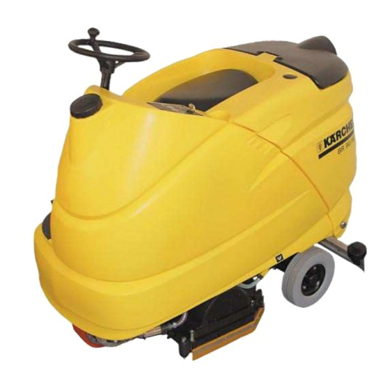
- Page 1 New Unit Information BR/BD 75/140 R BR/BD 90/140 R 1.246- . . . New Unit Information 03.2004 5.905-888...
- Page 2 Technical Features BR/BD 75/140 R, BR/BD 90/140 R Drive unit system Vacuum system – 3-wheel running gear with front wheel steering – Suction motor (long life) vacuums the dirty and front wheel-hub motor with electro-magne- water into the dirty water tank. tic brake.
- Page 3 BR/BD 75/140 R, BR/BD 90/140 R Unit Functions View from front (BR-Version) Steering wheel Drive unit pedal Control panel Front wheel, wheel hub motor Cap, fresh-water tank Lateral sealing strip, spring-loaded Fresh-water tank 10 Brush head, BR version Cover, main control printed circuit board 11 Coarse dirt pan (BR version only) Central battery connector (X1) 12 Seat...
- Page 4 Unit Functions BR/BD 75/140 R, BR/BD 90/140 R View from rear (BR-Version) Cover, main control printed circuit board Deflector wheel, suction bar Brush head, BR version Drain hose, dirty water tank Lateral sealing strip, spring-loaded Suction hose Coarse dirt pan (BR version only) 10 Dirty water tank Supporting castor for suction bar, optional 11 Cover, dirty water tank...
- Page 5 BR/BD 75/140 R, BR/BD 90/140 R Unit Functions Suction bar Drain hose, dirty water tank Note: Suction hose As a standard, the front rubber strip is Deflector wheel with star handle for grooved and the rear one is smooth. In case replacing/rotating the rubber strips of wear, both rubber strips can be rotated to Star handle, for installing the suction bar...
- Page 6 Unit Functions BR/BD 75/140 R, BR/BD 90/140 R Dirty water tank Tank cover Fluff strainer, air intake suction motor Float switch (S17) Seal, tank cover Page 6 / 71 New Unit Information 03.2004...
- Page 7 BR/BD 75/140 R, BR/BD 90/140 R Unit Functions Brush head (BR-Version) Brush head (BR version) Front wing nut, for securing the mounting plate Deflector wheel Spring for lateral sealing strip mounting plate Lateral sealing strip Mounting plate for sealing strip, spring- loaded Adjusting screw, brush pattern Rear wing nut, for securing the mounting...
- Page 8 Unit Functions BR/BD 75/140 R, BR/BD 90/140 R Brush head (BD-Version) Brush head (BD version) Deflector roller Disc brush Side sealing strip, spring loaded Brush head bracket Page 8 / 71 New Unit Information 03.2004...
- Page 9 BR/BD 75/140 R, BR/BD 90/140 R Unit Functions Battery ORIGINAL – Connecting terminal minus pole Note: Connecting terminal plus pole The dirty water tank (8) can only be lifted if Connection cable the dirty water has been drained. Battery (G1) Central battery connector (X1) = EMERGENCY STOP Air outlet hose, suction motor...
- Page 10 Unit Functions BR/BD 75/140 R, BR/BD 90/140 R Battery REVISED Connecting terminal minus pole Note: Connecting terminal plus pole The dirty water tank (8) can only be lifted if Connection cable the dirty water has been drained. Battery (G1) Central connector (X1) = EMERGENCY STOP Filling hose Suction motor (M3, EC long life)
- Page 11 BR/BD 75/140 R, BR/BD 90/140 R Unit Functions Central battery connector REVISED ORIGINAL Connection cable from the block battery EMERGENCY STOP function Connection cable (auxiliary contact S32) All the unit’s electrical components are connec- ted to the block battery via the central connector. to the control panel ORIGINAL If the upper section (5) is pulled off, the whole unit...
- Page 12 Unit Functions BR/BD 75/140 R, BR/BD 90/140 R Battery charger Central connector (X1) - upper section with handle Plug for connection with the battery charger Battery charger Central connector (X1) - lower section Mains cable, battery charger Page 12 / 71 New Unit Information 03.2004...
- Page 13 BR/BD 75/140 R, BR/BD 90/140 R Unit Functions Control panel ORIGINAL REVISED New Unit Information 03.2004 Page 13 / 71...
- Page 14 Unit Functions BR/BD 75/140 R, BR/BD 90/140 R Control panel (up to software version 2.5) ORIGINAL Item Name Function 1 Indicator light (green) Lights up when warning beacon light is switched on. 2 Indicator light (green) Lights up if working lights are switched on. 3 "Working light"...
- Page 15 BR/BD 75/140 R, BR/BD 90/140 R Unit Functions Control panel (up to software version 2.5) ORIGINAL Item Name Function 21 Indicator light (green) – Flashes if water function is activated. – Lights up if water pump is running and metering valve is open.
- Page 16 Unit Functions BR/BD 75/140 R, BR/BD 90/140 R Control panel (from display software version V1.0) REVISED Item Name Function 1 Indicator light (green) Lights up when warning beacon light is switched on. 2 Indicator light (green) Lights up if working lights are switched on. 3 "Working light"...
- Page 17 BR/BD 75/140 R, BR/BD 90/140 R Unit Functions Control panel (from display software version V1.0) REVISED Item Name Function 19 "Info" push-button Appears on the display: – Battery status (bar diagram). – Temperature of the main control printed circuit board. –...
- Page 18 Unit Functions BR/BD 75/140 R, BR/BD 90/140 R Control panel (from display software version V1.0) REVISED Item Name Function 29 Indicator light (green) Lights up if push-button 28 is activated. – Drive pedal, forward drive When the drive pedal is pressed the following functions are activated (if pre-selected): –...
- Page 19 BR/BD 75/140 R, BR/BD 90/140 R Unit Functions Control panel printed ciruit board, view reverse side ORIGINAL Connection cable, to main control printed circuit board Control panel printed circuit board (A2) Key switch (S1) Flat cable, connection to plastic foil con- trol panel New Unit Information 03.2004 Page 19 / 71...
- Page 20 Unit Functions BR/BD 75/140 R, BR/BD 90/140 R Control panel printed ciruit board, view reverse side REVISED Connection cable, to main control printed circuit board Control panel printed circuit board (A2) Key switch (S1) Flat cable, connection to plastic foil con- trol panel Page 20 / 71 New Unit Information 03.2004...
- Page 21 BR/BD 75/140 R, BR/BD 90/140 R Unit Functions Main control printed circuit board ORIGINAL New Unit Information 03.2004 Page 21 / 71...
- Page 22 Unit Functions BR/BD 75/140 R, BR/BD 90/140 R Main control printed circuit board ORIGINAL Connection instrument panel printed Note: circuit board (X2) For connections on terminal strips con- Terminal strip (X11) cerned and fuse values see circuit diagram Processor 0.088-555 Terminal strip (X1) Tightening torques for: Terminal strip (X9)
- Page 23 BR/BD 75/140 R, BR/BD 90/140 R Unit Functions Main control printed circuit board REVISED New Unit Information 03.2004 Page 23 / 71...
- Page 24 Unit Functions BR/BD 75/140 R, BR/BD 90/140 R Main control printed circuit board REVISED Terminal strip (X1) Note: Terminal strip (X204) The new main control printed circuit board Terminal strip (X200) 2.816-067 will be installed as of Terminal strip (X201) manufacturing number 10800.
- Page 25 BR/BD 75/140 R, BR/BD 90/140 R Unit Functions Steering Steering column The steering column (4) with internal steering rod (9) is fixed to the base frame (5) by four retaining bolts (1). The steering movement of the steering wheel is transferred via the steering rod (9) to the steering head (7) via the ring gear (9).
- Page 26 Unit Functions BR/BD 75/140 R, BR/BD 90/140 R Seat contact switch, junction box Seat contact switch The seat contact switch (1) is located on the underside of the drivers’ seat (2). To get to the seat contact switch (1), the seat (2) must be lifted at the rear and pushed back with a jolt.
- Page 27 BR/BD 75/140 R, BR/BD 90/140 R Unit Functions Water system Water filter ORIGINAL The water filter removes contaminations from the fresh-water to protect the water pump. It is located at the front, on the left-hand side beneath the fresh-water tank. Water filter (ALT) REVISED Water filter...
- Page 28 Unit Functions BR/BD 75/140 R, BR/BD 90/140 R Water system Air bleeder valve (only BR-head) If the water pump is switched off and the meter- ing valve is closed the air bleeder valve (3) opens and allows the water in the hose between the metering valve and the T-junction to drain.
- Page 29 BR/BD 75/140 R, BR/BD 90/140 R Unit Functions Water system PIN Round connection plug, Square connection plug, valve 4.580-599 valve 4.580-605 ORIGINAL REVISED Pin 4 Pin 3 Pin 2 Pin 1 Battery voltage 24 Volt (+) Battery voltage 24 Volt (+) Earth 0 Volt 24 Volt if water pump ON 0 Volt if water pump OFF...
- Page 30 Unit Functions BR/BD 75/140 R, BR/BD 90/140 R Brush head - BR version REVISED Brush head from above Terminal strip brush motors (EXT.X2) Water inlet hose Brush head, top bracket Springs (3x) Brush head from above (REVISED) Brush head from below Side sealing strip Brush roller, front Side sealing strip...
- Page 31 BR/BD 75/140 R, BR/BD 90/140 R Unit Functions Brush head BD version Brush head from above Retainer plate, sealing strip left Sealing strip, left Deflector wheel Drive motor (M2), disc brush left Terminal strip, brush motors (EXT.X2) Fresh-water inlet, right side Retainer plate, sealing strip right Brush head from above Sealing strip, right...
- Page 32 Unit Functions BR/BD 75/140 R, BR/BD 90/140 R Functional diagram Cover, dirty water tank 12 Drive belt Float switch (S17) 13 Brush motor (M2, M2.1) Fluff strainer 14 Brush head Cover, fresh-water tank 15 Coarse-dirt container (only BR version) Fresh-water tank 16 Fresh-water hose to the brush head REVISED Shut-off valve...
- Page 33 BR/BD 75/140 R, BR/BD 90/140 R Basic Settings and Service Procedures Control panel test REVISED The control panel test enables the user to check the function of the plastic foil control panel and the indicator lamps. The item numbers refer to the “control panel”...
- Page 34 Basic Settings and Service Procedures BR/BD 75/140 R, BR/BD 90/140 R Test mode ORIGINAL Access to test mode The user can use test mode to check the function of all the setings separately from each other. The item numbers given for the push- buttons refer to the illustration of the Bild control panel.
- Page 35 BR/BD 75/140 R, BR/BD 90/140 R Basic Settings and Service Procedures Test mode ORIGINAL Press the "brush motor" (9) push-button Indicator light (19 green) goes off. again Both brush motors switch off. Press the "Memo" (12) push-button This push-button has no function in the test mode.
- Page 36 Basic Settings and Service Procedures BR/BD 75/140 R, BR/BD 90/140 R Test mode ORIGINAL Press "forward drive" (13) push-button. Indicator light (14 green) lights up. Seat contact switch must be closed by Magnetic brake is released. loading (sitting on) the seat. Indicator light (26 red) goes off.
- Page 37 BR/BD 75/140 R, BR/BD 90/140 R Basic Settings and Service Procedures Test mode REVISED Access to test mode The user can use test mode to check the function of all the setings separately from each other. The item numbers given for the push- buttons refer to the illustration of the control panel (page 14).
- Page 38 Basic Settings and Service Procedures BR/BD 75/140 R, BR/BD 90/140 R Test mode REVISED Press the "Info" (19) push-button See page 17. Press the "Increase brush pressure" (8 +) Brush head rises as long as the push-button push-button is pressed. Press the "Reduce brush pressure"...
- Page 39 BR/BD 75/140 R, BR/BD 90/140 R Basic Settings and Service Procedures Test mode REVISED Information which can be displayed by consecutively pressing the “Memo” button (12) Display: Meaning: battery voltage Battery voltage [resolution: 0.1V] xx.xV I_traction: Drive motor current [resolution: 1A] I_brush: Brush motor current [resolution: 1A] I_vacuum:...
- Page 40 Basic Settings and Service Procedures BR/BD 75/140 R, BR/BD 90/140 R Setup menu ORIGINAL Change settings Press the “Increase brush pressure” (8) push- button to increase the settings. Press the “Reduce brush pressure” (11) push- button to reduce the settings. Save settings Press the “reverse drive”...
- Page 41 BR/BD 75/140 R, BR/BD 90/140 R Basic Settings and Service Procedures Setup menu REVISED Change settings Press the “Increase brush pressure” (8) push- button to increase the settings. Press the “Reduce brush pressure” (11) push- button to reduce the settings. Save settings Press the “reverse drive”...
- Page 42 Basic Settings and Service Procedures BR/BD 75/140 R, BR/BD 90/140 R Setup menu REVISED Display with Possible settings Explanations manufacture settings language German or English Display text appears in German or English englisch Battery low 19.5-22.5 Volt If the set battery low voltage is 0.1 Volt increment reached, the unit can only be driven, Voltage...
- Page 43 BR/BD 75/140 R, BR/BD 90/140 R Troubleshooting Troubleshooting ORIGINAL REVISED Faults could occur in the unit, with or without a corrective measure in the table below). Before text display. You should always proceed as fol- carrying out any service work on the unit al- lows: ways turn the key switch to the position “0”...
- Page 44 Troubleshooting BR/BD 75/140 R, BR/BD 90/140 R Troubleshooting ORIGINAL Faults with text in the display Corrective measures seat switch – Load seat (at least 10 kg). Display must disappear after. 4 sec. – Check/replace seat contact switch. – Check cable connections to the printed circuit board for interruptions/breaks and correct the fault.
- Page 45 BR/BD 75/140 R, BR/BD 90/140 R Troubleshooting Troubleshooting ORIGINAL Faults with text in the display Corrective measures error! – Remove your foot from the drive pedal before switching on the key switch. incorrect start – With the pedal in the "off" position, check the sensor voltage at connector X6 on the main control printed circuit board between the Contacts 1 and 3.
- Page 46 Troubleshooting BR/BD 75/140 R, BR/BD 90/140 R Troubleshooting ORIGINAL Faults with text in the Corrective measures display overload – Check/adjust front wheel brake. – Check cable connections to the main control printed brake circuit board for interruptions/breaks and correct any faults.
- Page 47 BR/BD 75/140 R, BR/BD 90/140 R Troubleshooting Troubleshooting REVISED text i Faults with n the Corrective measures display seat switch – Load seat, with at least 10 kg, display must disappear open! after approx. 1 sec. – Check/replace seat contact switch. –...
- Page 48 Troubleshooting BR/BD 75/140 R, BR/BD 90/140 R Troubleshooting REVISED Faults with text in the Corrective measures display error! – Check the set of rechargeable batteries. The voltage at the battery post terminals must be less than 32 V! high battvoltage release –...
- Page 49 BR/BD 75/140 R, BR/BD 90/140 R Troubleshooting Troubleshooting REVISED Faults with ext in the corrective measures display battery – Move the machine to the charging station and charge the battery. empty -> charge! battery totally – Manually unlock the front wheel brake. (Attention! The machine no longer has any braking discharged! effect!)
- Page 50 Troubleshooting BR/BD 75/140 R, BR/BD 90/140 R Unit does not operate Insert/Check/Replace central battery connector (X1) Set multimeter to Volt setting and check the cen- tral battery connector (1), replace any defective parts. Check the connection cable (3) – Disconnect the positive battery post ORIGINAL –...
- Page 51 BR/BD 75/140 R, BR/BD 90/140 R Troubleshooting Not enough water Fill fresh-water tank – Open the fresh-water tank cap and fill with fresh- water and cleaning agent. Check/clean/replace water filter – Unscrew the water filter (1) at both ends of the hose.
- Page 52 Troubleshooting BR/BD 75/140 R, BR/BD 90/140 R Not enough water Check function of metering valve (Y2) and replace as necessary Check function of metering valve, replace if nec- essary (see also chapter water system). Metering valve (Y2) (ORIGINAL) Metering valve (Y2) (REVISED) New Unit Information 03.2004 Page 52 / 71...
- Page 53 BR/BD 75/140 R, BR/BD 90/140 R Troubleshooting Suction not adequate Clean/replace the rubber strips on the suction bar Clean the rubber strips (5) on the suction bar and check for damage/wear. Rotate/replace as ne- cessary. – Unscrew the retaining bolts (4), remove the deflector wheels (3) with metal spacers (2) and pull off the rubber strip retainers (1) from both sides of the suction bar (6).
- Page 54 Troubleshooting BR/BD 75/140 R, BR/BD 90/140 R Suction not adequate Check/clean/replace the seal at the dirty water tank cover Check the dirty water tank seal (2) for damage and dirt, clean/replace as necessary. Clean fluff strainer in the dirty water tank The fluff strainer (1) can become blocked, de- pending on how the unit is used and how dirty the surfaces to be cleaned are.
- Page 55 BR/BD 75/140 R, BR/BD 90/140 R Troubleshooting Suction beam lifting motor Micro switch adjustment If the suction bar does not reach the most upper or lower position and/or has no movement, the micro switches must first be checked before replacing the lifting motor. –...
- Page 56 Troubleshooting BR/BD 75/140 R, BR/BD 90/140 R Dirty water tank overflows Check/Replace float switch (S17) The float switch (1) must be replaced if it fails to switch off when the max. level of the dirty water in tank has been reached. –...
- Page 57 BR/BD 75/140 R, BR/BD 90/140 R Troubleshooting Poor cleaning results Check/Remove brush head for foreign matter When foreign matter is on the brush roller this can influence the cleaning result. – Remove all foreign matter. Splashguard The side splashguard (2) must lie on the floor when the brush head (1) is lowered, so that water cannot escape from the side.
- Page 58 Troubleshooting BR/BD 75/140 R, BR/BD 90/140 R Poor cleaning results Check/adjust the brush pattern – Coat a flat surface with chalk and move the unit over the chalked area. – Lower the brush head using the test mode and allow the brushes to rotate for approx. 3 sec. –...
- Page 59 BR/BD 75/140 R, BR/BD 90/140 R Troubleshooting Poor cleaning results Replace the brush rollers (BR version) – Loosen the wing nut (1), remove the wing nut (5) and pull off the cover (4). – Pull the brush (2) out and check for wear, re- place as necessary.
- Page 60 Troubleshooting BR/BD 75/140 R, BR/BD 90/140 R Poor cleaning results Adjust the contact pressure to the brush rollers – Loosen the cable gland (3), remove the retai- ning screws (5) and the cover (4). – Move piston (2) of the the lifting motor (1) in the test mode to 32 ±...
- Page 61 BR/BD 75/140 R, BR/BD 90/140 R Troubleshooting Poor cleaning results Check/replace disc brushes (BD version) – Raise the brush head. – Lift up the disc brushes (2), rotate then by ap- prox. 45 degrees and then remove them from below. –...
- Page 62 Troubleshooting BR/BD 75/140 R, BR/BD 90/140 R Drive sensor ORIGINAL Adjust drive sensor (B1) – Remove the retaining screws of the floor panel (1) and lift up the floor panel. – Remove the cover of the main control printed circuit board. –...
- Page 63 BR/BD 75/140 R, BR/BD 90/140 R Troubleshooting Drive sensor REVISED Floor panel Adjust drive sensor (B1) Drive sensor (B1) – Remove the retaining screws of the floor panel (1) and lift up the floor panel. Unit housing – Switch on the unit in test mode. Adjusting screws (2x), drive sensor –...
- Page 64 Troubleshooting BR/BD 75/140 R, BR/BD 90/140 R Electromagnetic brake Y1 adjustment Check adjustment The tolerance between the magnet coil (1) and the pressure plate (2) must be 0,3 mm (.012 in). – Switch the unit off at the key switch (S0). –...
- Page 65 BR/BD 75/140 R, BR/BD 90/140 R Troubleshooting Safety checks ORIGINAL Seat contact switch (S16) Braking function The seat contact switch (S16) should be chec- If the mechanical brake in the front wheel fails the ked every 100 hours. motor brake acts automatically, so that in the worst case with maximum speed 2.4 km/h the 1.
- Page 66 Troubleshooting BR/BD 75/140 R, BR/BD 90/140 R Safety checks ORIGINAL “Watchdog” fault message The “Watchdog” function monitors the entire control function of the unit. It should be checked every 100 operating hours. You will need a test connector (special tool) to do this. 1.
- Page 67 BR/BD 75/140 R, BR/BD 90/140 R Troubleshooting Safety checks REVISED Seat contact switch (S16) Braking function The seat contact switch (S16) should be chec- If the mechanical brake in the front wheel fails the ked every 100 hours. motor brake acts automatically, so that in the worst case with maximum speed 2.4 km/h the 1.
- Page 68 Troubleshooting BR/BD 75/140 R, BR/BD 90/140 R Working time needed to replace important parts Components Working time Note Modules (Min.) Battery Exchange only with a lift possible. Tightening torque of the polls 23 Nm ± 1 Nm Fuses F1-F4 Main control printed circuit board Central battery connector Disconnect the battery before replacing the including EMERGENCY-...
- Page 69 BR/BD 75/140 R, BR/BD 90/140 R Troubleshooting Working time needed to replace important parts Components Working time Note Modules (Min.) Dirty water tank float switch 15 Dirty water tank Seat switch Seat Suction bar lifting motor Micro switches are adjustable Drive motor carbon Drive motor brushes...
- Page 70 Troubleshooting BR/BD 75/140 R, BR/BD 90/140 R Working time needed to replace important parts Components Working time Note Modules (Min.) Disc brush drive belt See analog disc brush drive motor Replace roller brush, disc See analog roller brush, disc brush drive motor brush, drive motor carbon brushes Brush head lifting motor...
- Page 71 BR/BD 75/140 R, BR/BD 90/140 R Technical Features Technical specifications Unit Type Unit No. Circuit diagram Operating Maintenance Spare instructions booklet parts list BR 75/140 R 1.246-101 0.088-555 (ORIG.) 5.960-442 5.950-583 5.958-942 24 V 0.088-682 (REV.) BR 75/140 R Pack 1.246-121 0.088-555 (ORIG.) 5.960-442 5.950-583...
Need help?
Do you have a question about the BR 75/140 R Series and is the answer not in the manual?
Questions and answers