
Related Manuals for Skope EziCore TCE Series EziCore TCE650N


Summary of Contents for Skope EziCore TCE Series EziCore TCE650N
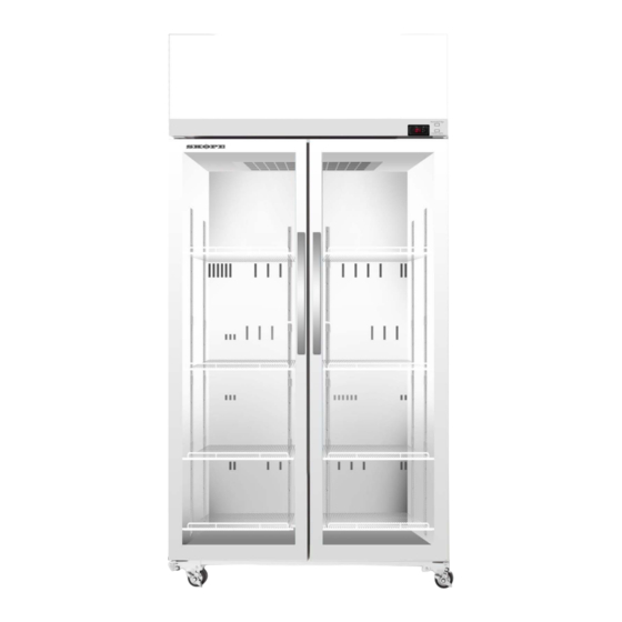
- Page 1 EziCore TCE Series SKOPE Upright Fridge Hydrocarbon SKOPE IDs: TCE650N:ET65BYN, TCE1000N:ET10BYN...
- Page 2 E-mail: skope@skope.com Website: www.skope.com Trademark Infringement The SKOPE trademark on this product is infringed if the owner, for the time being, does any of the following: • Applies the trade mark to the product after its state, condition, get-up or packaging has been altered in any manner •...
-
Page 3: Table Of Contents
Contents Specifications Models..........5 Installation Installation Guidelines . - Page 4 Cabinet Assembly ........39 TCE650N .
-
Page 5: Specifications
1 Specifications Models This service manual is applicable to the EziCore TCE top mount fridges listed in the table below. Refer to the relevant product specification sheet (available on the SKOPE website: www.skope.com) for specifications. Table 1: Model specifications Series... -
Page 6: Installation
TCE650N:ET65BYN, TCE1000N:ET10BYN 2 Installation Installation Guidelines When installing this cabinet, ensure you consider and meet the installation guidelines below. Ventilation Surface Door Opening Climate Class The installation surface Ensure all ventilation Allow adequate space for The fridge must be requirements below must be capable of the door/s to open and installed in an environment... -
Page 7: Sign Assembly And Refrigeration Cartridge
TCE650N:ET65BYN, TCE1000N:ET10BYN Sign Assembly and Refrigeration Cartridge To transport the cabinet through a lower clearance doorway, you will need to remove the sign assembly and refrigeration cartridge. Follow Procedure 20, “To remove the refrigeration cartridge,” on page 26. Door Handles Fitting Door The cabinets are fitted with door handles when they are shipped or supplied. -
Page 8: Shelves
TCE650N:ET65BYN, TCE1000N:ET10BYN Procedure 2: To remove a door handle Before you start Make sure you have a screwdriver and flat end tool, to remove the mounting hardware. 1. Use the flat end tool to gently pry off the handle end caps. This will expose fixing screw heads. Plastic handle Counterbore hole 2. -
Page 9: Wiring
TCE650N:ET65BYN, TCE1000N:ET10BYN 3 Wiring TCE650N and TCE1000N GNYE GNYE S21-L P21-L S21-L P21-L P21-N S21-N P21-N S21-N EMC Filter EMC Filter Wire colours Evaporator Fan Evaporator Fan Black Brown T1-1 T1-1 S15-2 P15-2 S15-2 P15-2 S22-2 P22-2 S22-2 P22-2 P22-3 S22-3 P22-3 S22-3 P15-1 S15-1 P15-1 S15-1... -
Page 10: Electronic Controller
(see below). Setpoint SKOPE does not recommend that the setpoint range be changed unless it is absolutely necessary, and then only by small increments at a time. Procedure 5: To change the temperature setpoint range 1. -
Page 11: Messages And Alarms
TCE650N:ET65BYN, TCE1000N:ET10BYN Messages and The following table explains messages and alarms that the electronic controller displays. Alarms Table 2: Chunchang C212 messages and alarms Display Description The cabinet’s internal temperature. The temperature is what the sensor inside the fridge detects, and not necessarily the product temperature. However, they may be very close depending on how the controller is set to sense temperature. -
Page 12: Replacement Procedures
Fluorescent or LED tubes cannot be used in place of LED modular lights. IMPORTANT Replace the light with the same SKOPE OEM part. DO NOT use alternative LED strip or tube lights, or fluorescent tubes. Refer to Spare Parts for replacement light specifications: •... - Page 13 TCE650N:ET65BYN, TCE1000N:ET10BYN Procedure 7: To replace an interior light assembly 1. Disconnect the cabinet from the mains power supply (see page 12). Top strip Side strip 2. Gently remove the side plastic strip Screwdriver with a slotted screwdriver to expose the failed assembly’s black water- proof connector.
- Page 14 TCE650N:ET65BYN, TCE1000N:ET10BYN Procedure 8: To replace the LED driver 1. Disconnect the cabinet from the mains power supply (see page 12). 2. Lift up the sign’s front panel and unplug the White 4-way white 4-way connector near the switches at the connector back of the sign’s front panel.
- Page 15 TCE650N:ET65BYN, TCE1000N:ET10BYN Procedure 9: To replace the sign lighting loom and cabinet lighting loom (continued) 3. Unplug the relevant connectors: • Sign lighting loom: 1) Remove the sign clips to Black 2-way release the front panel. connector in the front 2) Unplug the black 2-way connector in the front, and the 4 ×...
-
Page 16: Sign Light
TCE650N:ET65BYN, TCE1000N:ET10BYN Sign Light The sign is lit by an LED modular light which can be replaced. Procedure 10: To replace the sign light 1. Disconnect the cabinet from the mains power supply (see page 12). 2. Remove the sign’s front panel (see steps 2 and 3 in Procedure 8 on page 14). Sign clips LED light strip 3. -
Page 17: Adjusting Door Tension
TCE650N:ET65BYN, TCE1000N:ET10BYN Procedure 12: To refit the door Door pin 1. Lift the door onto the bottom hinge using the door pin to help position it correctly. Bottom hinge 2. Fit the top hinge to the top of the door and cabinet, and partially fix it in place. 3. -
Page 18: Adjusting Door Height
TCE650N:ET65BYN, TCE1000N:ET10BYN Procedure 14: To adjust the door tension (continued) 3. Use a tool to apply tension to the door via the capstan. First, rotate the capstan against the Tensioning tool door opening direction to remove any slack. Once resistance is felt, continue to rotate 180° to provide tension. -
Page 19: Electronic Controller
TCE650N:ET65BYN, TCE1000N:ET10BYN Electronic Controller Controller The electronic controller is located within the sign assembly. The module sits in a cut-out in the sign. It is mounted with a snap-fit feature on the sides of the controller. Location Sign’s front panel Controller display Procedure 16: To access the controller 1. -
Page 20: Controller Flexes
TCE650N:ET65BYN, TCE1000N:ET10BYN Controller To connect the controller, plug the control probe flex and controller power flex into the correct sockets on the controller. To disconnect the controller, simply unplug the control probe flex and Flexes controller power flex. Controller Control power flex probe flex (black) -
Page 21: Control Probe
Ensure you have read and understood this manual before starting any servicing. Important • SKOPE hydrocarbon refrigeration systems must only be serviced by appropriately skilled and qualified refrigeration mechanics. • Servicing a sealed refrigeration system must occur at a hydrocarbon workshop or service area with dedicated hydrocarbon equipment and personal protective equipment (PPE). - Page 22 Check all components including the electronic controller and electrical systems. Ensure your work area is well ventilated. IMPORTANT Use only dedicated hydrocarbon SKOPE OEM spare parts. DO NOT use alternative parts. For safety compliance, use only SKOPE-supplied components specified for the appliance.
-
Page 23: On-Site Work
The cartridge must only be used on a SKOPE hydrocarbon-compliant cabinet. Refer to the cabinet rating label to determine if the cabinet is suitable for use with a hydrocarbon cartridge. -
Page 24: Not Cooling Fault
TCE650N:ET65BYN, TCE1000N:ET10BYN The model and serial number are both printed on the cartridge rating/serial number label attached to the top of the side of the cover. Compressor Condenser coil Compressor electrics Cartridge electrics box LSUBHCNI Cartridge electrics box cover Evaporator coil Evaporator fan Cartridge electrics box cover... - Page 25 TCE650N:ET65BYN, TCE1000N:ET10BYN Procedure 19: To determine if there is a sealed system fault Before you start 1. If a customer reports a “not cooling” fault, and it has been established that the cabinet is not cooling, follow the “On-site Work Procedure” on page 35. 2.
-
Page 26: Removing The Cartridge
The hydrocarbon cartridge must only be used on a hydrocarbon-compliant cabinet. New spare part refrigeration cartridges supplied by SKOPE do not come with the evaporator tub lid, top strap brackets or hold down brackets. When replacing a faulty top mount refrigeration cartridge, keep these parts for the new replacement cartridge. - Page 27 TCE650N:ET65BYN, TCE1000N:ET10BYN The evaporator tub lid, top strap brackets and hold down brackets can be ordered in addition to the refrigeration cartridge if required. See page 43 for spare part numbers. Top strap brackets Evaporator tub lid Hold down bracket Hold down bracket Procedure 21: To replace a cartridge...
-
Page 28: Cartridge Cover
TCE650N:ET65BYN, TCE1000N:ET10BYN Cartridge Remove the cartridge cover to access parts within the cartridge assembly. Cover Procedure 22: To remove the refrigeration cartridge cover 1. Disconnect the cabinet from the power supply (see page 12). 2. Remove the refrigeration cartridge (see page 26). 3. -
Page 29: Condenser Fan
TCE650N:ET65BYN, TCE1000N:ET10BYN Procedure 23: To remove and open the cartridge electrics box assembly (continued) 3. Undo the fixing screw at the top of the electrics box cover, and remove the cover. 4. Unplug all cartridge plugs from the cartridge electrics box. 5. - Page 30 Refer to the label on the electrics box cover to identify the condenser fan plug and socket in the electrics box. IMPORTANT Replace the motor with the same SKOPE OEM part. DO NOT use alternative parts. It is important that the fan blade and/or fan motor is replaced with the same part to ensure safety, correct alignment and refrigeration performance, and compliance.
-
Page 31: Evaporator Fan
(complete with fan motor and fan blade) can be lifted off the evaporator tub once the refrigeration cartridge cover has been removed. IMPORTANT Replace the motor with the same SKOPE OEM part. DO NOT use alternative parts. It is important that the evaporator fan blade and/or fan motor is replaced with the same part to ensure safety, correct alignment and refrigeration performance, and compliance. - Page 32 TCE650N:ET65BYN, TCE1000N:ET10BYN Procedure 27: To access the evaporator fan assembly Before you start If a customer reports a “not cooling” fault, and it has been established that the cabinet is not cooling, follow the “On-site Work Procedure” on page 35. 1.
-
Page 33: Compressor
TCE650N:ET65BYN, TCE1000N:ET10BYN Procedure 29: To replace the evaporator fan motor (continued) Evaporator fan motor’s white 4-way connector 3. Trace the cable back to the connector (near the compressor electrics) and unplug it. 4. Detach the fan motor from the fan mounting bracket by removing the four screws from the mounting bracket. -
Page 34: Compressor Electrics
TCE650N:ET65BYN, TCE1000N:ET10BYN over 220 volts, so ensure the voltage does not drop at start-up. If the voltage does drop, ensure the cartridge has a direct power supply (not from a multi-box or extension cord). IMPORTANT To eliminate possible vibration noise, ensure no pipes touch the plastic base and condenser assembly. -
Page 35: On-Site Work Procedure
TCE650N:ET65BYN, TCE1000N:ET10BYN On-site Work Procedure If a customer reports a “not cooling” fault, and it has been established that the cabinet is not cooling, follow the procedure below when making the service visit. Calibrate the gas Isolate at the Create a 1.5 m Is the mains detector (away mains socket... - Page 36 TCE650N:ET65BYN, TCE1000N:ET10BYN On-site work procedure (continued) Return the faulty cartridge to the service depot. Create a safe work area in an Is the refrigeration open, well-ventilated space system considered around the faulty cartridge. to have gas leak? Ensure there are no hazards, ignition sources or drains.
-
Page 37: Spare Parts
TCE650N:ET65BYN, TCE1000N:ET10BYN 6 Spare Parts Main Assembly TCE650N Table 9: Parts – Main assembly TCE650N Description Page Cabinet assembly Page 39 Door assembly Page 41 Sign assembly Page 42 Page 43 Cartridge assembly Electrics box assembly Page 45 Spare Parts Service Manual... -
Page 38: Tce1000N
TCE650N:ET65BYN, TCE1000N:ET10BYN TCE1000N Table 10: Parts – Main assembly TCE1000N Description Page Cabinet assembly Page 40 Door assembly Page 41 Sign assembly Page 42 Page 43 Cartridge assembly Electrics box assembly Page 45 Spare Parts Service Manual... -
Page 39: Cabinet Assembly
TCE650N:ET65BYN, TCE1000N:ET10BYN Cabinet Assembly TCE650N Table 11: Parts – Cabinet assembly TCE650N Description SKOPE Part No. Top hinge – right hand HB0070110582 Bottom hinge – right hand HB0070110851 Height adjustment block HB0070110581 Tension bracket HB0070110580 Wire shelf HB0070116489 Shelf support strip... -
Page 40: Tce1000N
TCE650N:ET65BYN, TCE1000N:ET10BYN TCE1000N Table 12: Parts – Cabinet assembly TCE1000N Description SKOPE Part No. Top hinge – left hand HB0070110583 Top hinge – right hand HB0070110582 Bottom hinge – left hand HB0070110850 Bottom hinge – right hand HB0070110851 Height adjustment block... -
Page 41: Glass Door Assembly
TCE650N:ET65BYN, TCE1000N:ET10BYN Glass Door Assembly Table 13: Parts – Glass door assembly Description SKOPE Part No. TCE650N TCE1000N Left hand door assembly – HB0070843179 Right hand door assembly HB0070843178 HB0070843180 Door handle HB0070202818E HB0070202818E Door handle cap HB0070202817E HB0070202817E Door gasket... -
Page 42: Sign Assembly
TCE650N:ET65BYN, TCE1000N:ET10BYN Sign Assembly Table 14: Parts – Sign assembly Description SKOPE Part No. TCE650N TCE1000N Sign assembly HB0070843779 HB0070843780 Sign back strip HB0070110813 HB0070110812 HB0074001527A (left side) LED light strip HB0074001541 (× 1) HB0074001527 (right side) 1 × light switch... -
Page 43: Cartridge Assembly - Uthcni-0061
TCE650N:ET65BYN, TCE1000N:ET10BYN Cartridge Assembly – UTHCNI-0061 Ordering The model and serial number are both printed on the cartridge rating/serial number label attached to the front of the cartridge. Before ordering spare parts, take note of the model and serial numbers. Spare Parts Service Manual... - Page 44 TCE650N:ET65BYN, TCE1000N:ET10BYN Table 15: Parts – Cartridge assembly Description SKOPE Part No. EziCore cartridge assembly* UBHCNI-0061 Cartridge plastic bottom HB0070206212D Condensate line HB0070702717 Drier bracket HB0070112920 Hold down bracket HB0070110815A Condensate pipe support HB0070206128 Compressor – Donper L96CU1 HB0074001387A Electrics box assembly (see page 45)
-
Page 45: Electrics Box Assembly
TCE650N:ET65BYN, TCE1000N:ET10BYN Electrics Box Assembly Table 16: Parts – Electrics box assembly Description SKOPE Part No. Electrics box assembly HB0070843783 HB0070207012A Cartridge electrics box enclosure front Electrical enclosure panel HB0070207014 EMI filter HB0074600001 HB0070207013A Cartridge electrics box enclosure rear –... -
Page 46: Maintenance
The owner should periodically wipe the inside and outside of the cabinet with a damp cloth, taking care to keep moisture away from electrical parts. Condenser To ensure trouble-free performance, SKOPE strongly recommends the cleaning schedule in Table 17, which will depend on: Coil •... - Page 47 TCE650N:ET65BYN, TCE1000N:ET10BYN Procedure 31: To clean the condenser coil (continued) 4. Refit the sign assembly and reconnect to the power supply. Important When refitting, ensure the tabs on the back of the sign are located in the notches on top of the cabinet, and that the sign is pushed fully in and secure.
-
Page 48: Troubleshooting
Check each parameter individually. Get the latest parameter • Incorrect parameters • Defrost cycle set by registering for and logging into the skope.com incorrect length website, or contacting Customer Service. • Fan not working • Loose plug Check all plugs are connected correctly. - Page 49 Product must not overhang the shelves. Diagnose and repair. If a system fault is found contact • Refrigeration system error (indicated by the electronic controller) SKOPE for information on how to proceed. • Frequent door opening Limit door openings. •...
- Page 50 SKOPE Industries Limited ABN: 73 374 418 306 AU: 1800 121 535 NZ: 0800 947 5673 skope@skope.com www.skope.com...
Need help?
Do you have a question about the EziCore TCE Series EziCore TCE650N and is the answer not in the manual?
Questions and answers