Table of Contents
Advertisement
Quick Links
This user's guide is for the TPS25810EVM-745 and explains how to get up and running with the
TPS25810 EVM, how to test specific features of the TPS25810, and an explanation of what happens
when different types of USB type-C devices are attached to the EVM.
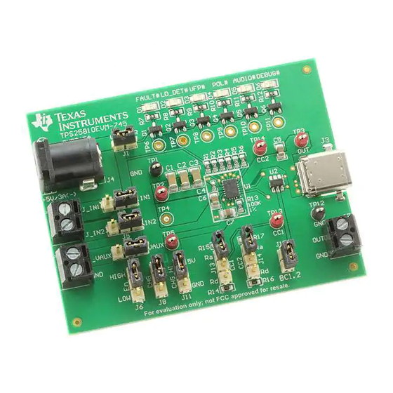
Power Adapter
(5 V/3 A) (–)
IN1
IN2
Power Cables
AUX
GND
SLVUAI0A – September 2015 – Revised September 2015
Submit Documentation Feedback
SLVUAI0A – September 2015 – Revised September 2015
TPS25810EVM-745 User's Guide
Select Power
Output Signal LEDs
Source
Control Signals
Figure 1. TPS25810EVM
Copyright © 2015, Texas Instruments Incorporated
US Type-C
Input Simulation
TPS25810EVM-745 User's Guide
User's Guide
Enable
Backwards
Compatibility
USB Type-C
Cable Input
Output Load
Simulation
1
Advertisement
Table of Contents

Related Manuals for Texas Instruments TPS25810EVM-745


Summary of Contents for Texas Instruments TPS25810EVM-745
-
Page 1: Tps25810Evm
SLVUAI0A – September 2015 – Revised September 2015 TPS25810EVM-745 User's Guide This user's guide is for the TPS25810EVM-745 and explains how to get up and running with the TPS25810 EVM, how to test specific features of the TPS25810, and an explanation of what happens when different types of USB type-C devices are attached to the EVM. -
Page 2: Table Of Contents
Schematic Showing How CC1 and CC2 are Connected to Jumpers J14 and J15 Respectively ..............Simulating an UFP Device on the TPS25810EVM-745 ...... Simulating an UFP Device on the TPS25810EVM-745 With and Without an Output Load ..........Simulating a Non-UFP Powered Device on the TPS25810EVM-745 .......... -
Page 3: Introduction
(CC) lines and monitors each line to determine if and what type of USB device has been attached. For more information on the TPS25810, refer to the data sheet (SLVSCR1). SLVUAI0A – September 2015 – Revised September 2015 TPS25810EVM-745 User's Guide Submit Documentation Feedback Copyright © 2015, Texas Instruments Incorporated... -
Page 4: Schematic
Schematic www.ti.com Schematic Figure 2 is the schematic of the TPS25810EVM-745. LED_PWR 100k 100k 100k 100k 100k 100k FAULT# LD_DET# UFP# POL# AUDIO# DEBUG# Green Green Green Green Green Green 47µF 47µF 47µF 0.1µF J_IN1 Vin Range: IN1 and IN2 : 4.5 - 6.5 V : 2.9 - 5.5 V... -
Page 5: Test Points
See Figure 3 for jumper orientation. TPS25810 5-V/3- A Power Adapter TPS25810 Figure 3. Choosing the Right Power Source SLVUAI0A – September 2015 – Revised September 2015 TPS25810EVM-745 User's Guide Submit Documentation Feedback Copyright © 2015, Texas Instruments Incorporated... -
Page 6: Enabling And Configuring The Tps25810
Enabling and Disabling the TPS25810 The TPS25810 has an enable pin that creates a convenient way to turn on or turn off the device without interrupting the power source. On the TPS25810EVM-745 the TPS25810 can be enabled and disabled using jumper J6. See Figure 5 for enable and disable positions for jumper J6. -
Page 7: Jumper Connection For Each Broadcast Current Limit
To switch between these three levels, a HIGH or LOW voltage is set onto pins CHG and CHG_HI of the TPS25810. Refer to the data sheet for voltage levels required for CHG and CHG_HI to change the current limit levels. On the TPS25810EVM-745 jumpers J8 and J11 control the voltage level of CHG and CHG_HI pins respectively. -
Page 8: Tps25810Evm-745 Features
TPS25810EVM-745 Features The TPS25810EVM-745 allows for all the features of the TPS25810 to be tested with and without a USB Type-C cable and external device. Below are the most common types of situations that can happen with the TPS25810EVM-745 and within each section is an explanation of how to test each situation with and without external components. -
Page 9: Simulating An Ufp Device On The Tps25810Evm-745
Cable Orientation ON ON ON ON Figure 8. Simulating an UFP Device on the TPS25810EVM-745 6.3.1 UFP Load Detect Feature When a UFP device is connected to the TPS25810, it is also possible to test the load detect feature. The load detect feature is enabled when the CHG and CHG_HI pins are set HIGH to Vaux. -
Page 10: Simulating An Ufp Device On The Tps25810Evm-745 With And Without An Output Load
UFP# POL# Figure 9. Simulating an UFP Device on the TPS25810EVM-745 With and Without an Output Load Connecting a Non-UFP Powered Device The way the TPS25810 detects a powered device is by checking if one of the CC lines is connected to a Rd resistor value. -
Page 11: Simulating An Audio Accessory Device On The Tps25810Evm-745
CC lines are connected to a Ra resistor value. This connection is unique in the sense that both Ra resistors must be connected to the CC lines within a small time frame (usually about 10 ms). The easiest way to test this mode on the TPS25810EVM-745 is by connecting an audio accessory device through the USB port. -
Page 12: Tps25810 Output Signals
Refer to Table 1 to see what conditions for the CC lines are necessary to activate this mode. TPS25810EVM-745 User's Guide SLVUAI0A – September 2015 – Revised September 2015 Submit Documentation Feedback Copyright © 2015, Texas Instruments Incorporated... -
Page 13: Board Layout
Rd resistor. This mode can be used for factory testing or similar functional modes. Board Layout The following images show the silkscreen, top, bottom, and assembly layers of the TPS25810EVM-745. Figure 14. Top Silkscreen SLVUAI0A – September 2015 – Revised September 2015... -
Page 14: Top Solder Mask
Board Layout www.ti.com Figure 15. Top Solder Mask Figure 16. Top Layer TPS25810EVM-745 User's Guide SLVUAI0A – September 2015 – Revised September 2015 Submit Documentation Feedback Copyright © 2015, Texas Instruments Incorporated... -
Page 15: Bottom Layer
Board Layout www.ti.com Figure 17. Bottom Layer Figure 18. Top Assembly SLVUAI0A – September 2015 – Revised September 2015 TPS25810EVM-745 User's Guide Submit Documentation Feedback Copyright © 2015, Texas Instruments Incorporated... -
Page 16: Bill Of Materials
TP10, TP11 Testpoint Unless otherwise noted, all parts may be substituted with equivalents. Alternate part number: SNT-100-BK-G; Alternate manufacturer: Samtec TPS25810EVM-745 User's Guide SLVUAI0A – September 2015 – Revised September 2015 Submit Documentation Feedback Copyright © 2015, Texas Instruments Incorporated... -
Page 17: Pcb Layout Recommendations
Have the input and output traces as short as possible and wide enough for 3A (6A is using two TPS25810) SLVUAI0A – September 2015 – Revised September 2015 TPS25810EVM-745 User's Guide Submit Documentation Feedback Copyright © 2015, Texas Instruments Incorporated... - Page 18 Revision History www.ti.com Revision History Changes from Original (September 2015) to A Revision ....................Page ....................... • Updated EVM board layer image Revision History SLVUAI0A – September 2015 – Revised September 2015 Submit Documentation Feedback Copyright © 2015, Texas Instruments Incorporated...
- Page 19 STANDARD TERMS AND CONDITIONS FOR EVALUATION MODULES Delivery: TI delivers TI evaluation boards, kits, or modules, including any accompanying demonstration software, components, or documentation (collectively, an “EVM” or “EVMs”) to the User (“User”) in accordance with the terms and conditions set forth herein. Acceptance of the EVM is expressly subject to the following terms and conditions.
- Page 20 FCC Interference Statement for Class B EVM devices NOTE: This equipment has been tested and found to comply with the limits for a Class B digital device, pursuant to part 15 of the FCC Rules. These limits are designed to provide reasonable protection against harmful interference in a residential installation.
- Page 21 【無線電波を送信する製品の開発キットをお使いになる際の注意事項】 開発キットの中には技術基準適合証明を受けて いないものがあります。 技術適合証明を受けていないもののご使用に際しては、電波法遵守のため、以下のいずれかの 措置を取っていただく必要がありますのでご注意ください。 1. 電波法施行規則第6条第1項第1号に基づく平成18年3月28日総務省告示第173号で定められた電波暗室等の試験設備でご使用 いただく。 2. 実験局の免許を取得後ご使用いただく。 3. 技術基準適合証明を取得後ご使用いただく。 なお、本製品は、上記の「ご使用にあたっての注意」を譲渡先、移転先に通知しない限り、譲渡、移転できないものとします。 上記を遵守頂けない場合は、電波法の罰則が適用される可能性があることをご留意ください。 日本テキサス・イ ンスツルメンツ株式会社 東京都新宿区西新宿6丁目24番1号 西新宿三井ビル 3.3.3 Notice for EVMs for Power Line Communication: Please see http://www.tij.co.jp/lsds/ti_ja/general/eStore/notice_02.page 電力線搬送波通信についての開発キットをお使いになる際の注意事項については、次のところをご覧くださ い。http://www.tij.co.jp/lsds/ti_ja/general/eStore/notice_02.page SPACER EVM Use Restrictions and Warnings: 4.1 EVMS ARE NOT FOR USE IN FUNCTIONAL SAFETY AND/OR SAFETY CRITICAL EVALUATIONS, INCLUDING BUT NOT LIMITED TO EVALUATIONS OF LIFE SUPPORT APPLICATIONS.
- Page 22 Notwithstanding the foregoing, any judgment may be enforced in any United States or foreign court, and TI may seek injunctive relief in any United States or foreign court. Mailing Address: Texas Instruments, Post Office Box 655303, Dallas, Texas 75265 Copyright © 2015, Texas Instruments Incorporated...
- Page 23 IMPORTANT NOTICE Texas Instruments Incorporated and its subsidiaries (TI) reserve the right to make corrections, enhancements, improvements and other changes to its semiconductor products and services per JESD46, latest issue, and to discontinue any product or service per JESD48, latest issue.
- Page 24 Mouser Electronics Authorized Distributor Click to View Pricing, Inventory, Delivery & Lifecycle Information: Texas Instruments TPS25810EVM-745...
Need help?
Do you have a question about the TPS25810EVM-745 and is the answer not in the manual?
Questions and answers