Advertisement
Quick Links
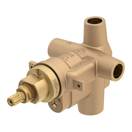
3 Port Pressure Balancing Shower Valve
46-1-BODY, 46-1X-BODY
Installation Brief
Model Number
46-1-BODY
Temptrol 3 port pressure balancing
Shower valve body (46-1X-BODY
with built-in service stops)
For California Residents
WARNING: This product contains
chemicals known to the State of
California to cause cancer, birth defects,
or other reproductive harm.
Rough-in Installation
Installing control valve, piping & fittings
Reference rough-in dimension illustration
on page 2 as required.
1)
Determine wall thickness
■ Determine type of wall and wall
thickness where valve will be mounted.
■ Consider whether to use mounting plate
by reviewing figure 2 below.
■ Skip ahead to
if mounting
Step 3
plate will not be used.
2)
Attach mounting plate to valve
Seat mounting plate against valve
assembly as illustrated in figure 1.
Walls for using T-177 valve mounting plate
Fiberglass or acrylic walls (required)
Plaster or other type walls (optional)
1/16" (2 mm) min 1/2" (13 mm) max
Protective shield
When mounting plate is used,
then shield is optional for
protecting end of valve during
installation.
"snap on-off"
p/n T-176
Temptrol
Tools & Materials
Plumbers
Putty
(valve without IPS ports shown)
3)
Attach protective shield
■ Reference figure 2 to determine
whether shield is required.
■ Attach plastic protective shield by
snap fitting over end of valve spindle.
nished
wall
p/n T-177
wall cutout hole size
3-1/2" (89 mm) min
4" (102 mm) max
Figure 2 Mounting valve (valve without IPS ports shown)
®
1
2
3
4
Figure 1 Mounting
plate
Dry wall, plaster or other type wall
1/2" (13 mm) or greater
Reference rough-in
Ensure valve's
drawing on page 2
mounting plate
is ush against
inner wall
Finished wall must be
ush with back side of
protective shield surface
Protective shield
"snap on-off"
(required when
valve mounting
plate is not used)
wall cutout hole size
3-1/2" (89 mm) min
4" (102 mm) max
Need Help?
Contact Symmons customer service at
P: (800) 796-6667, F: (781) 848-2250
gethelp@symmons.com
Mon - Fri 7:30 am - 7:00 pm EST
Please check Symmons website
for technical help, the latest product
information and warranty policy.
www.symmons.com/service
4)
Install piping, fittings and
control valve
Piping and fittings not supplied
■ Control Valve
Install valve through cutout hole in
wall as specified in figure 2 below and
dimension illustration on page 2.
■ Showerhead (S on valve)
Pipe from outlet port on valve marked
to showerhead mounting arm location.
■ Hot & Cold Supply (H & C)
Pipe hot water supply to valve input
marked
and cold water supply to
H
valve input marked
nished wall
dimensional
S
.
C
Advertisement

Subscribe to Our Youtube Channel
Related Manuals for Symmons Temptrol 46-1-BODY


Summary of Contents for Symmons Temptrol 46-1-BODY
- Page 1 46-1-BODY, 46-1X-BODY Installation Brief Need Help? Model Number Tools & Materials 46-1-BODY Contact Symmons customer service at Temptrol 3 port pressure balancing P: (800) 796-6667, F: (781) 848-2250 Shower valve body (46-1X-BODY gethelp@symmons.com with built-in service stops) Mon - Fri 7:30 am - 7:00 pm EST For California Residents ...
- Page 2 Important! Do not substitute ■ Tighten packing nut for positive ■ Check for leaks around valve Tub Spout with restrictive frictional resistance as handle is assembly and all pipe fittings. fittings such as CPVC rotated from shutoff position across outlet accessories such as a ledge adjustment range.
- Page 3 Cap washer Cap assembly washer repair kit (T-12A) packing (T-16) packing nut Temptrol Valve Replacement Parts and Optional Tools Symmons Valve Body Type Part Description 46-1-BODY 46-1X-BODY Number √ √ TA-4 HOT & COLD seat repair kit (optional tool p/n T-35A/B) ...
- Page 4 ■ ■ ■ ■ Symmons Industries, Inc. 31 Brooks Drive Braintree, MA 02184 Phone: (800) 796-6667 Fax: (800) 961-9621 ■ ■ ■ ■ Copyright © 2017 Symmons Industries, Inc. symmons.com gethelp@symmons.com ZV-3236 REV 0 041317...
Need help?
Do you have a question about the Temptrol 46-1-BODY and is the answer not in the manual?
Questions and answers