Table of Contents
Advertisement
Quick Links
Advertisement
Table of Contents

Subscribe to Our Youtube Channel
Related Manuals for Tecnoware EVO DSP PLUS MODULAR


Summary of Contents for Tecnoware EVO DSP PLUS MODULAR
- Page 1 Uninterruptible Power Supply EVO DSP PLUS MODULAR User’s manual Manuale utente...
-
Page 3: Table Of Contents
Index User’s Manual - English ................1 Safety Warnings ..................1 1 Introduction ..................2 2 General Characteristics ................5 3 Receipt and site selection ...............5 Site Selection ................. 5 UPS Unpacking ................6 Moving the Cabinet ................8 4 Operational Principles ................9 Block Diagram of UPS ............... 9 Operation Modes ................ - Page 4 6 Power Module ..................46 Power Module ID ................47 7 Static Tranfer Switch (STS) Module ............49 Interface and Communication ............49 7.1.1 Dry Contact Ports ................49 7.1.1.1 X1-Remote EPO Input Port ..............50 7.1.1.2 X4 - Maintenance Bypass Switch State Port ..........51 7.1.1.3 X6 - Battery Cabinet Temperature Detection Port .........
- Page 5 11.7.2.1 Install Power Module of UPS Rack1 ............84 11.7.2.2 Install Power Module of UPS Rack2 ............84 11.7.3 Parallel Function Setting ..............85 11.7.4 Parallel Cable Connection ..............85 11.7.5 Parallel System Turn ON Procedure ............86 12 Technical Characteristics ..............87 13 Maintenance..................
- Page 6 © Copyright 2019 TECNOWARE s.r.l. All rights reserved. All trademarks are property of their respective owners. TECNOWARE s.r.l. Via Montetrini, 2E – Molino del Piano – Florence – Italy www.tecnoware.com This manual has been printed and edited by TECNOWARE s.r.l. October 2023 edition – Version 2.0...
-
Page 7: User's Manual - English
User’s Manual – English Safety Warning Read this manual carefully and completely before installing and using the TECNOWARE EVO DSP PLUS Modular Uninterruptible Power Supply, which, from here after, will also be referred to as UPS. The UPS must be used only by properly trained personnel. To ensure correct and safe ... -
Page 8: Introduction
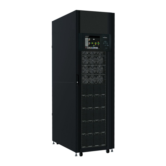
3. Static Transfer Switch (STS) Module 4. Power Modules 5. Battery Modules Figure 1.1 - UPS EVO DSP PLUS Modular (on the left: with closed front door; on the right with open door) User’s manual UPS EVO DSP PLUS Modular... - Page 9 ENGLISH UPS EVO DSP PLUS Modular is fully Modular (in the Figure 1.2 you can see 2 examples of UPS EVO DSP PLUS Modular). The structure is made from a 19-inch Rack Cabinet with all necessary 19-inch Rack Modules inside, mounted according to the specifications requested by the customer.
- Page 10 Read this manual carefully before using the UPS EVO DSP Modular; it includes important safety warnings and useful advices for correct use and installation. UPS EVO DSP PLUS Modular is constantly being developed and improved: consequently, your unit may differ somewhat from the description contained in this manual.
-
Page 11: General Characteristics
ENGLISH 2 General Characteristics UPS EVO DSP PLUS Modular has all the advanced features, which guarantee maximum reliability and safety: • Double-Conversion ON-LINE Transformerless technology • Fully modular architecture with multiple UPS Modules and Battery Modules in a single Rack Cabinet •... -
Page 12: Ups Unpacking
Use a forklift to move the cabinet to installed area. Refer to Figure 3.1. Please make sure the bearing capacity of forklift is sufficient. Please follow the order in Figure 3.2 to remove carton and foams. Figure 3.1 User’s manual UPS EVO DSP PLUS Modular... - Page 13 Remove 4 fixing cabinet plates and loosen leveling feet by rotating them counterclockwise. Then, move the cabinet from the pallet. Refer to Figure 3.4. To fix the cabinet in position, simply rotate leveling feet clockwise. Refer to Figure 3.5. UPS EVO DSP PLUS Modular User’s manual...
-
Page 14: Moving The Cabinet
UPS, please turn the four leveling feet counter clockwise to raise them off the ground. This protects the leveling feet from damage when moving the UPS. Refer to Figure 3.6. Figure 3.6 User’s manual UPS EVO DSP PLUS Modular... -
Page 15: Operational Principles
4 Operational Principles 4.1 Block Diagram of UPS Figure 4.1a – Block and Wiring Diagram for dual Inputs (80KVA~210KVA cabinet) Figure 4.1b – Block and Wiring Diagram for dual Inputs (only 300KVA cabinet) UPS EVO DSP PLUS Modular User’s manual... - Page 16 ENGLISH Figure 4.1c – Block and Wiring Diagram for single Input (80KVA~210KVA cabinet) Figure 4.1d – Block and Wiring Diagram for single Input (only 300KVA cabinet) User’s manual UPS EVO DSP PLUS Modular...
-
Page 17: Operation Modes
ENGLISH 4.2 Operation Modes EVO DSP PLUS MODULAR is a Three-Phase, Four-Wire On-Line, Double-Conversion UPS that permits operation in the following modes: • Standby Mode • Line Mode • Battery Mode • Bypass Mode • ECO Mode • Shutdown Mode •... -
Page 18: Line Mode
Battery. The Inverter filters the DC power and converts it into pure and stable AC power to the load. Figure 4.3 – Line Mode Diagram (up: 80KVA~210KVA cabinet; down: only 300KVA cabinet) User’s manual UPS EVO DSP PLUS Modular... -
Page 19: Battery Mode
In battery mode, the Rectifier delivers power from the Battery and supplies DC power to the Inverter. The Inverter filters the DC power and converts it into pure and stable AC power to the load. Figure 4.4 – Battery Mode Diagram (up: 80KVA~210KVA cabinet; down: only 300KVA cabinet) UPS EVO DSP PLUS Modular User’s manual... -
Page 20: Bypass Mode
If the transference is caused by a recoverable reason, the UPS will turn back to Line Mode when abnormal situation has been solved. Figure 4.5 – Bypass Mode Diagram (up: 80KVA~210KVA cabinet; down: only 300KVA cabinet) User’s manual UPS EVO DSP PLUS Modular... -
Page 21: Eco Mode
Bypass to Inverter. In order to shorten the transfer time, the Rectifier and Inverter are working when the UPS is in ECO mode. Figure 4.6 – ECO Mode Diagram (up: 80KVA~210KVA cabinet; down: only 300KVA cabinet) UPS EVO DSP PLUS Modular User’s manual... -
Page 22: Shutdown Mode
When the UPS enters this Mode, it is going to shut off the control power of UPS. The Rectifier, Charger and Inverter will be all shutdown. Figure 4.7 – Shutdown Mode Diagram (up: 80KVA~210KVA cabinet; down: only 300KVA cabinet) User’s manual UPS EVO DSP PLUS Modular... -
Page 23: Maintenance Bypass Mode (Manual Bypass)
UPS becomes unavailable e.g., during a maintenance procedure. Before entering the Maintenance Bypass Mode, make sure the Bypass power source is normal. Figure 4.8 – Maintenance Bypass Mode Diagram (up: 80KVA~210KVA cabinet; down: only 300KVA cabinet) UPS EVO DSP PLUS Modular User’s manual... -
Page 24: Control Panel Description
There is no power output for the load. Load on Inverters Green Inverters not operating Load on Battery Flashing Low Battery BATTERY Battery Converter is normal and Battery is charging UPS fault Flashing UPS alarm FAULT/ALARM Normal User’s manual UPS EVO DSP PLUS Modular... -
Page 25: Lcd Display Description
5.2 LCD Display Description 5.2.1 Initial Screen Upon powering on, the UPS will execute POST (Power-On Self-Test). The initial screen will remain approximately 5 seconds as shown below. Figure 5.2 – Initial Screen UPS EVO DSP PLUS Modular User’s manual... -
Page 26: Main Screen (Home)
Power Module icon with ID no. No Power Module Power Module Output ON Power Module Output OFF Power Module Charger ON Power Module Charger OFF Power Module fault Power Module is operated normally. User’s manual UPS EVO DSP PLUS Modular... -
Page 27: Control Menu
Date and Time: it shows current date and time. 5.2.3 CONTROL Menu Touch icon to enter into the CONTROL Menu as shown in Figure 5.5 and 5.6. Figure 5.5 - CONTROL Menu Tree UPS EVO DSP PLUS Modular User’s manual... - Page 28 Touch any control option directly. Then, Confirmation Screen will pop up. Touch icon to confirm command or touch icon to cancel command as shown in Figure 5.7. Figure 5.7 - Confirmation Screen page To return to the Main Screen touch the HOME icon. User’s manual UPS EVO DSP PLUS Modular...
-
Page 29: Measurement Menu
Modules. In both cases you can choose to monitor the values of Input, Output, Bypass, Load or Battery. Please refer to Figure 5.8, 5.9 and 5.10. All detailed measurement items are listed in Table 5-4. Figure 5.8 - MEASUREMENT Menu Tree Figure 5.9 – System Measurement Screens UPS EVO DSP PLUS Modular User’s manual... - Page 30 ENGLISH Figure 5.10 – Module Measurement Screens User’s manual UPS EVO DSP PLUS Modular...
-
Page 31: Setup Menu
SETUP Menu. It’s required to enter password to access GENERAL, SYSTEM, BATTERY, PRE-ALARM and PARALLEL Submenus as shown in Figure 5.11 and 5.12. Figure 5.11 - SETUP Menu Tree UPS EVO DSP PLUS Modular User’s manual... - Page 32 Table 5-5: All setting items in SETUP Menu Authorization UPS operation Mode Admini- User Setting item strator Model Name Language Time Change Password Baud Rate General Audible Alarm Factory Reset EEPROM Reset EPO Function Save Setting User’s manual UPS EVO DSP PLUS Modular...
- Page 33 Stop by Battery Capacity Battery Age Alert Temperature Compensation Charging Voltage Auto-Restart Battery Voltage Pre-Alarm UPS Parallel Parallel Independent Battery “Y” means that this setting item can be set in this operation mode. UPS EVO DSP PLUS Modular User’s manual...
-
Page 34: Setup-General Submenu
The SETUP-GENERAL Screen and Setting options are shown in Figure 5.14. SETUP-GENERAL Setting can be set in any operating mode. Please check Table 5-6 “SETUP-GENERAL Setting List” for the details. Figure 5.14 - SETUP-GENERAL Screen User’s manual UPS EVO DSP PLUS Modular... - Page 35 EPO Function • Normal Open Active (Default) 0000 Password Set New Password. The default Password is: Save all settings to EEPROM. Save Settings Use this feature to save the setting(s) you have done. UPS EVO DSP PLUS Modular User’s manual...
- Page 36 Maximum Charging Current Battery Low/Shutdown Setting Periodic Battery Test Battery Test Interval Battery Stop by Time Stop by Battery Voltage Stop by Battery Capacity Battery Age Alert Temperature Compensation Charging Voltage Auto-Restart Battery Voltage Pre-Alarm User’s manual UPS EVO DSP PLUS Modular...
-
Page 37: Setup-System Submenu
Please check Table 5-8 “SETUP-SYSTEM Setting List” for the details. If an option is not available under specific Mode, the Warning Screen will appear such as in Figure 5.16. Figure 5.15 - SETUP-SYSTEM Screen Figure 5.16 - Warning Screen UPS EVO DSP PLUS Modular User’s manual... - Page 38 Total Power: the QTY of Power Modules Redundancy: the QTY of Redundant Power Modules Redundancy MUST be set after UPS installation or the QTY of Power Module is changed. Set Charger Test: Charger Test • Disable (Default) • Enable User’s manual UPS EVO DSP PLUS Modular...
-
Page 39: Setup-Battery Submenu
SETUP-BATTERY Setting can be set only when UPS is operated in Standby Mode. If it’s not in Standby Mode, the Warning Screen will appear as shown in Figure 5.16. Please check Table 5-9 “SETUP-BATTERY Setting List” for the details. Figure 5.17 - SETUP-BATTERY Screen UPS EVO DSP PLUS Modular User’s manual... - Page 40 • 0 (mV/°C) (Default) Compensation Set Battery Charging Voltage (2.30~2.35V): Charging • 2.35V (Default) Voltage Set Battery Float Voltage (2.23~2.35V): • 2.29V (Default) Auto-Restart Set Auto-Restart Battery Voltage (0 or 12.0V~13.0V): Battery • 0V (Default) Voltage User’s manual UPS EVO DSP PLUS Modular...
-
Page 41: Setup-Pre-Alarm Submenu
Range • +/- 1Hz • +/- 2Hz • +/- 3 Hz • +/- 4Hz (Default) Set UPS Overload Percentage (40~100%): • 100% (Default) Load Set UPS Load Unbalanced Percentage (20~100%): • 100% (Default) UPS EVO DSP PLUS Modular User’s manual... -
Page 42: Setup-Parallel Submenu
Figure 5.19 - SETUP-PARALLEL Screen Table 5-11: SETUP-PARALLEL Setting List Setting Item Sub Item Explanation Set UPS Parallel: UPS Parallel • Disable (Default) • Enable Set Indipendent Battery: Indipendent Battery • Disable (Default) • Enable User’s manual UPS EVO DSP PLUS Modular... -
Page 43: Information Menu
Figure 5.21 - INFORMATION-IDENTIFICATION Screen 5.2.6.2 INFORMATION–SYSTEM Submenu When INFORMATION-SYSTEM Submenu is selected, the Nominal Power, Nominal Voltage, Nominal Frequency … etc. information will be displayed, as shown in Figure 5.22 and 5.23. UPS EVO DSP PLUS Modular User’s manual... -
Page 44: Information-Battery Submenu
Figure 5.23 – INFORMATION-SYSTEM Screen page 2 5.2.6.3 INFORMATION–BATTERY Submenu When INFORMATION-BATTERY Submenu is selected, the information such as Battery Nominal Voltage, Capacity, Charging Current … etc. will be displayed as shown in Figure 5.24. User’s manual UPS EVO DSP PLUS Modular... -
Page 45: Events Menu
Figure 5.25 – MAIN Screen with Alarm/Warning icon Touch icon to enter into EVENTS Menu, for checking the information about Events. There are three SubMenus: CURRENT EVENTS, HISTORY EVENTS and RESET ALL EVENTS (see Figure 5.26). UPS EVO DSP PLUS Modular User’s manual... -
Page 46: Events-Current Events Submenu
“UPS Mode Changes”) and control action execution (refer to Table 5-15 “Control Execution”) will be saved in History Events. Refer to Figure 5.28 for the details. *NOTE: Please refer to chapter 6.1 “Power Module ID” to identify Power Module ID address. User’s manual UPS EVO DSP PLUS Modular... -
Page 47: Events-Reset All Events Submenu
After entering correct password, it will pop up reconfirmed screen. Then, touch icon to reset all events or touch icon to cancel this action as shown in Figure 5.30 Figure 5.29 – EVENTS-RESET ALL EVENTS Screen UPS EVO DSP PLUS Modular User’s manual... -
Page 48: Alarm List
T phase inverter output is short-circuited Fault! RS Inverter Voltage Short R-S inverter output is short-circuited Fault! ST Inverter Voltage Short S-T inverter output is short-circuited Fault! TR Inverter Voltage Short T-R inverter output is short-circuited User’s manual UPS EVO DSP PLUS Modular... - Page 49 Neutral loss Warning! Internal Initial Fail As stated Warning! Comm Syn Signal Fail Communicate synchronization signal fail Warning! Comm. TRIG0 Fail Communicate trigger signal fault Warning! Power Stage loss Power stage is not detected UPS EVO DSP PLUS Modular User’s manual...
-
Page 50: History Record
Setup! Battery Shutdown Voltage Setup! Periodic Battery Test Setup! Stop By Time Setup! BATTERY Age Alert Setup! Temperature Compensation Setup! Charging Voltage Setup! PRE-ALARM Setup! UPS Parallel Setup! Independent Battery Setup! Auto-Restart Battery Voltage User’s manual UPS EVO DSP PLUS Modular... - Page 51 Control! System Turn On Control! System Turn Off Control! Manual Battery Test Control! Cancel Battery Test Control! Turn To Bypass Control! Shutdown Restore Control! Cancel Shutdown Control! Charger Turn On Control! Charger Turn Off UPS EVO DSP PLUS Modular User’s manual...
- Page 52 Up to 10 Power Modules can be connected into the same rack cabinet, to increase the power of UPS EVO DSP PLUS Modular. Each Power Module can be set as Parallel or Redundant, according to customer specifications. Figure 6.1 – Power Module 20 KVA Figure 6.2 – Power Module 30 KVA User’s manual UPS EVO DSP PLUS Modular...
- Page 53 SW1 and SW2 Switches are mounted on the Parallel board, which is located at the back of UPS cabinet. Refer to Figure 6.3. Figure 6.3 – SW1 and SW2 Switches on Parallel Board UPS EVO DSP PLUS Modular User’s manual...
- Page 54 Table 6-1: DIP Switch Setting and Module Address Module Address DIP SWITCH Module Address DIP SWITCH Table 6.2: Module ID Assignment SW1 - SW2 Module Address Module ID SW1 - SW2 Module Address Module ID User’s manual UPS EVO DSP PLUS Modular...
- Page 55 Dry Contact No Function Remote EPO input Port No use No use Maintenance Bypass Switch State Port No use Battery Cabinet Temperature Detection Port No use No use Figure 7.2 – Contact Ports UPS EVO DSP PLUS Modular User’s manual...
- Page 56 EPO function activates shutdown of the Rectifiers, Inverters and Static Transfer Switch. But it does not internally disconnect the input power supply. The default setting of the EPO function logic is Normally Opened (N.O.). User’s manual UPS EVO DSP PLUS Modular...
- Page 57 Communication between the UPS and Battery temperature detection board was through I2C communication protocol. X6 is the Battery Cabinet Temperature Detection Port. The port is shown in Figure 7.5 and described in Table 7-3. Figure 7.5 - Battery Cabinet Temperature Detection Port UPS EVO DSP PLUS Modular User’s manual...
- Page 58 RS232 cable only; to activate USB communication it is sufficient to connect the USB cable only. Connecting to the Web site www.tecnoware.com it is possible to download free of charge the updated UPS Management Software. 7.1.3...
- Page 59 8 Battery Module The Battery Module is a Battery Box that can be mounted in the rack cabinet of UPS EVO DSP PLUS Modular. The inside Batteries can be installed at factory or installed by qualified technical personnel authorized by TECNOWARE.
- Page 60 The Extended Cabinets don’t have the Battery Module compartments. The Battery has to be connected externally. Please consider the External Battery space and wiring gauge for installation. Standard Series Extended Series Cabinet Height Switch Unit Max. Power Module Battery Module Figure 9.1 – Type of UPS Cabinet User’s manual UPS EVO DSP PLUS Modular...
- Page 61 Inside the cabinet, there are Breakers, Static Transfer Switch (STS) Module, Power Module slots and Battery Module slots (Battery Module Slots is only for Standard Series). All wiring terminal blocks are located in the back of cabinet. Figure 9.2 – Type of UPS Cabinet UPS EVO DSP PLUS Modular User’s manual...
- Page 62 ENGLISH 9.2.1 Mechanical Data Dimensions UPS cabinet Width Depth Height 600mm 1100m 1475mm 600mm 1100m 2010mm Figure 9.3 – Dimensions User’s manual UPS EVO DSP PLUS Modular...
- Page 63 The Switch Unit of 300KVA cabinet has Maintenance Bypass Switch Only. Standard Series Extended Series Figure 9.4 – Front View (on the right 300KVA cabinet) 1. Switch Unit 2. Static Transfer Switch (STS) Module 3. Power Module 4. Battery Module UPS EVO DSP PLUS Modular User’s manual...
- Page 64 Unlock and open the rear door and you will see the rear panel of UPS. There is a Battery Breaker for internal battery modules in the Standard Series, but there isn’t any in the Extended Series. Standard Series Extended Series Battery Breaker Figure 9.5 – Rear View User’s manual UPS EVO DSP PLUS Modular...
- Page 65 For the Standard Series, there is a Battery Breaker for internal Battery Modules. You can see it when you open the rear door. Standard Series (42U) Extended Series (42U) Figure 9.6 – Front Breakers Battery Breaker Battery Breaker Standard Series (30U) Standard Series (42U) Figure 9.7 – Rear Breakers UPS EVO DSP PLUS Modular User’s manual...
- Page 66 9.2.5 Maintenance Bypass Switch (only in 300 KVA cabinet) After opening the front door, there is one Maintenance Bypass Switch (only in 300 KVA cabinet) Figure 9.8 – Maintenance Bypass Switch (only in 300 KVA cabinet) User’s manual UPS EVO DSP PLUS Modular...
- Page 67 For UPS Grounding For UPS Grounding Includes one Grounding terminal. Battery Input Connects an external Battery Includes: Positive (+), Negative (-) and Block Cabinet Neutral (N) terminals. Figure 9.9 – Standard Series (30U) Terminal Blocks UPS EVO DSP PLUS Modular User’s manual...
- Page 68 ENGLISH Figure 9.10 – Standard Series (42U) Terminal Blocks Figure 9.11 – Extended Series (42U) Terminal Blocks User’s manual UPS EVO DSP PLUS Modular...
- Page 69 2. Be sure the Ready Switch on the front panel of the Power Module is in the “ ” (Unlock) position, because the Module is NOT Ready to start. 3. Insert the Power Module into an unoccupied slot by two persons. UPS EVO DSP PLUS Modular User’s manual...
- Page 70 Figure 10.2 – Insert the Power Module 4. Secure the Power Module to the cabinet by fixing the screws at the front panel of the Power Module. Figure 10.3 – Secure the Power Module to the cabinet User’s manual UPS EVO DSP PLUS Modular...
- Page 71 2. The FAULT Led (red color) is lit to indicate the Power Module Output is OFF and disconnected from UPS system. Figure 10.5 – FAULT Led 3. Use a screwdriver to remove the four screws from fixing holes. 4. Two people pull out together and remove the Power Module from its slot. UPS EVO DSP PLUS Modular User’s manual...
- Page 72 Figure 10.7 – Install the required Battery Modules 3. Install the required Battery Modules according to the power and autonomy of the Modular System 4. Secure the Battery Module to the cabinet by fixing the screws of the Battery Module. User’s manual UPS EVO DSP PLUS Modular...
- Page 73 Output Neutral Battery Ground Phases Phases EVO DSP PLUS Modular 20KVA EVO DSP PLUS Modular 30KVA EVO DSP PLUS Modular 40KVA EVO DSP EVO Modular 60KVA EVO DSP EVO Modular 80KVA EVO DSP EVO Modular 90KVA EVO DSP EVO Modular 100KVA...
- Page 74 (Power Cables) To Bypass SUPPLY (Power Cables) To Critical Load (Power Cables) To External BATTERY (Power Cables) Figure 10.9 - UPS Wiring For UPS wiring, please refer to Figure 9.9, 9.10 and 9.11. User’s manual UPS EVO DSP PLUS Modular...
- Page 75 The instructions below describe the operations to correctly connect the UPS to an external Battery Box supplied by Tecnoware. We suggest to use ONLY Battery Box supplied by TECNOWARE. TECNOWARE declines any responsibilities if this rule is not followed. Before starting whichever operation be sure that the Battery Breaker of Battery Box is in “OFF”...
- Page 76 There are no internal parts in the UPS, which are user serviceable. Any repair or maintenance work must be performed exclusively by qualified technical personnel authorized by TECNOWARE. TECNOWARE declines any responsibility if this warning is disregarded. Disregard for these warnings may lead to a risk of electric shock to operators.
- Page 77 The UPS will enter into Standby Mode, if the setting of Bypass Mode is disabled. Figure 11.2 – LCD Panel indicates Standby Mode Or the UPS will enter into Bypass Mode, if the setting of Bypass Mode is enabled. UPS EVO DSP PLUS Modular User’s manual...
- Page 78 6. Press Power On/Off Button for two seconds to enter into Line Mode as shown in Figure 11.5. After turning on, UPS will does Self-Test and starts Inverter up. UPS will be transferred to Line mode when all Power Modules are ready. Figure 11.4 – Power On/Off Button User’s manual UPS EVO DSP PLUS Modular...
- Page 79 Power Modules and STS Module as shown below. Battery Start Button Figure 11.6 – Battery Start Button 4. After pressing the Battery Start Button, UPS will enter into Standby Mode, as shown in Figure 11.7. UPS EVO DSP PLUS Modular User’s manual...
- Page 80 5. Before UPS enters into Shutdown Mode, please press Power On/Off Button for two seconds as shown in the diagram below. Figure 11.8– Power On/Off Button 6. Then, UPS will enter Battery Mode as shown in the diagram below. User’s manual UPS EVO DSP PLUS Modular...
- Page 81 The UPS can operate in Standby Mode or Bypass Mode, depending on the Bypass Mode Setting. The LCD diagrams are shown below (see Figure 11.10 and 11.11). Figure 11.10 - Bypass Mode Setting is Disabled Figure 11.11 - Bypass Mode Setting is Enabled UPS EVO DSP PLUS Modular User’s manual...
- Page 82 If the Bypass Mode Setting is Enabled: the UPS stays in Bypass Mode and No AC Input is indicated on LCD Panel (Input Led is OFF). The LCD diagram is shown below (Figure 11.14). Bypass Mode Setting is Enabled Figure 11.14 - LCD Panel indicates Bypass Mode and NO AC input is indicated User’s manual UPS EVO DSP PLUS Modular...
- Page 83 System Turn OFF to turn off the UPS. After turning OFF, the UPS will transfer to Standby Mode or Bypass Mode, depending on the Bypass Mode Setting. Proceed as explained in the chapter 11.3.1. UPS EVO DSP PLUS Modular User’s manual...
- Page 84 The procedure of switching into Maintenance Bypass shall only be executed by authorized technical service personnel. During Maintenance Bypass operation, loads are fed directly from Bypass mains. Therefore, no protection against mains disturbances or interruptions is present. User’s manual UPS EVO DSP PLUS Modular...
- Page 85 Step 2: Switch ON the Maintenance Bypass Breaker as Switch the handle toward downsize as shown shown below. below. Step 3: Switch OFF the Main Breaker (Q1) as shown Step 4: below. UPS EVO DSP PLUS Modular User’s manual...
- Page 86 • The Power Modules and STS module have • The Power Modules and STS module have been installed well. been installed well. Switch ON the Main Breaker (Q1) as shown below Step 2: User’s manual UPS EVO DSP PLUS Modular...
- Page 87 Lock back the mechanical lock plate as shown below. below Step 5: Turn ON the UPS as explained in chapter 11.1 “AC Turn ON the UPS as explained in chapter 11.1 “AC Step 6: Startup”. Startup”. UPS EVO DSP PLUS Modular User’s manual...
- Page 88 11.5 Low Battery and Automatic Restart EVO DSP PLUS Modular reaches the Low Battery condition whenever, during working in Battery Mode, the Batteries reach a charge level allowing the connected devices to operate for few minutes more. See chapter 5.2.5.3 “SETUP-BATTERY Submenu”...
- Page 89 11.7 UPS Installation for Parallel Rack System This chapter explains how to install and set up a single UPS EVO DSP PLUS Modular to a Parallel Rack System. EVO DSP PLUS Modular are designed according to high MTBF figures with increased reliability but in case of necessity, a second EVO DSP PLUS Modular can be connected in parallel for supplying the very critical load to increase reliability.
- Page 90 For the cabinets which can insert more than 5 Power Modules, there are two Parallel Boards inside the cabinet. Both of these two SW2 have to be adjusted simultaneously. Refer to chapter 6.1 to set the Module Address. User’s manual UPS EVO DSP PLUS Modular...
- Page 91 Parallel Cable. Please refer to connector's position as shown below (Figure 11.20 and 11.21). For the cabinet with two Parallel Boards, please insert the connectors into any one of two boards. UPS EVO DSP PLUS Modular User’s manual...
- Page 92 Please confirm the System without any abnormal Event through the Panel Display (refer to chapter 5.2.7 “EVENTS Menu”). Turn ON the UPS through the Power On/Off Button or CONTROL Menu of the Control Panel (refer to chapter 5.2.3 “CONTROL Menu”). User’s manual UPS EVO DSP PLUS Modular...
- Page 93 ENGLISH 12 Technical Characteristics UPS EVO DSP PLUS Modular Power 300 KVA Nominal Active Power 300 KW Power Factor Technology On-Line Double Conversion Transformerless (VFI-SS-111) INPUT Rated Power 300 KVA Phases 3 Phases four-wire, with Neutral reference to the Bypass Neutral...
- Page 94 Windows, Linux, Unix, etc. SNMP Interface Optional OTHERS EPO (Emergency Power OFF) Included Dry Contact Interface Optional Manual Bypass for Maintenance Included Parallel Operating Mode Optional (up to 2 UPS) ECO Mode Selectable User’s manual UPS EVO DSP PLUS Modular...
- Page 95 (with 20KVA Modules) Number of Battery Layers (4 Battery Module on each layer) (*) in case of 8 x 30KVA Power Modules, one must be Redundant Technical data may change without prior notice UPS EVO DSP PLUS Modular User’s manual...
- Page 96 After it will be necessary to refer to qualified technical personnel. Original safety characteristics might not be if, for example, the UPS has visible damage or irregular operation. User’s manual UPS EVO DSP PLUS Modular...
- Page 97 After servicing the Module, push the Module into the cabinet and tighten the screws on both sides. Follow chapter 11.4.2 “Transfer to UPS Protection” procedure to transfer UPS into Bypass operation. Now it is possible to turn UPS on. UPS EVO DSP PLUS Modular User’s manual...
- Page 98 Open the front door of the UPS and the air filters are on the back of the door. Remove a fixing bar on either side of the air filter. Remove the air filter, and insert a clean one. Replace the fixing bar. User’s manual UPS EVO DSP PLUS Modular...
- Page 99 There are no internal parts in the UPS which are user serviceable. Any repair or maintenance work must be performed exclusively by qualified technical personnel authorized by TECNOWARE. TECNOWARE declines any responsibility if this warning is disregarded. LCD Message Explanation...
- Page 100 Check if the Input Voltage or Frequency is out of Warning! Turn On Abnormal As stated, range. Warning! Charge Fail As stated, Contact service personnel. Warning! EEPROM Fail EEPROM operation error Contact service personnel. User’s manual UPS EVO DSP PLUS Modular...
- Page 101 Change the repeated ID to release it. Or contact service personnel. If the described anomalies should continue despite the advised troubleshooting, or should they manifest in any other form, please contact: TECNOWARE SERVICE www.tecnoware.com UPS EVO DSP PLUS Modular User’s manual...
- Page 102 Directive 2014/35/EU and following amendments, the EMC (Electro-Magnetic Compatibility) Directive 2014/30/EU and following amendments. WARNING - EVO DSP PLUS Modular PLUS is a category C3 UPS product. This is a product for commercial and industrial application in the second environment. Installation restrictions or additional measures may be needed to prevent disturbances.
- Page 104 TECNOWARE s.r.l. www.tecnoware.com...
Need help?
Do you have a question about the EVO DSP PLUS MODULAR and is the answer not in the manual?
Questions and answers