Table of Contents
Advertisement
Quick Links
LOSSNAY HEAT RECOVERY VENTILATOR
HANDBOOK
MODELS
VL-250CZPVU-L-E
VL-250CZPVU-R-E
VL-250CZPVU-L-EG
VL-250CZPVU-R-EG
VL-250CZPVU-L-ERT
VL-250CZPVU-R-ERT
RC cover
(Optional)
P-RCC-E
Warning:
Repair work must be performed by the manufacturer, its service
agent or a similarly qualified person in order to avoid hazards.
Filter
(Optional)
P-250F-E
P-250SF-E
P-250MF-E
P-250PF-E
P-250PFH-E
P-250NF-E
September 2022
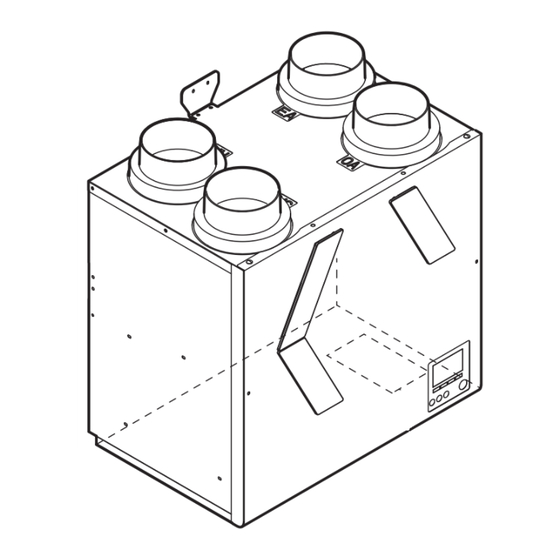
Nameplate
* The figure shows -R type.
The outer view of the product slightly
differs from that of the actual product.
Silencer box
(Optional)
P-250SB-E
No. U312
Advertisement
Table of Contents

Related Manuals for Mitsubishi Electric VL-250CZPVU-L-EG


Summary of Contents for Mitsubishi Electric VL-250CZPVU-L-EG
- Page 1 September 2022 No. U312 LOSSNAY HEAT RECOVERY VENTILATOR HANDBOOK MODELS VL-250CZPVU-L-E VL-250CZPVU-R-E VL-250CZPVU-L-EG VL-250CZPVU-R-EG VL-250CZPVU-L-ERT VL-250CZPVU-R-ERT Nameplate * The figure shows -R type. The outer view of the product slightly differs from that of the actual product. RC cover Filter...
-
Page 2: Table Of Contents
10. Service inspection list ..............42 11. Overhauling procedures .............. 43 44-64 12. Parts catalog ................63 65-101 VL-250CZPVU-L-E ..................64 66-71 VL-250CZPVU-R-E ..................70 72-77 VL-250CZPVU-L-EG ..................76 78-83 VL-250CZPVU-R-EG ..................82 84-89 VL-250CZPVU-L-ERT .................. 88 90-95 VL-250CZPVU-R-ERT .................. 94 96-101 ─ 2 ─... -
Page 3: Safety Precautions
1. Safety precautions Read the following precautions thoroughly before the maintenance, and then inspect and repair the product in a safe manner. The types and levels of danger that may arise if the product is handled improperly are described with the warning symbols shown below. -
Page 4: Changed Points
Instruction Manual and Installation Manual are provided in the local languages: Russian, Kazakh, Armenian, and Ukrainian. The structure and characteristic values of the product are not VL-250CZPVU-R-ERT VL-250CZPVU-R-E changed. VL-250CZPVU-L-EG VL-250CZPVU-L-E • Controller • High performance filter VL-250CZPVU-R-EG VL-250CZPVU-R-E 3. Names and functions of components Name... - Page 5 Installation example Notes - Make sure that the exhaust air connection has two or more confluence points with the piping from the bathroom. - Pre-heaters and electric dampers may be required in your region. - Read the instructions carefully in advance when using optional components and commercially available components.
-
Page 6: Specifications
3. The sound pressure level at 3 m is spherical. 4. Temperature exchange efficiency (%) is based on winter conditions. 5. Mitsubishi Electric measures figures in the chart according to EN13141-7:2010, and the characteristic curves are measured by chamber method. - Page 7 3. The sound pressure level at 3 m is spherical. 4. Temperature exchange efficiency (%) is based on winter conditions. 5. Mitsubishi Electric measures figures in the chart according to EN13141-7:2021, and the characteristic curves are measured by chamber method.
-
Page 8: Outside Dimensions
5. Outside dimensions VL-250CZPVU-L-E, VL-250CZPVU-L-EG, VL-250CZPVU-L-ERT Pipe guide (SA) RA: Return Air SA: Supply Air EA: Exhaust Air Pipe guide (OA) OA: Outdoor Air Pipe guide (EA) Pipe guide (RA) Wall mount hook top Wall bracket (accessory) φ122 Filter cover (RA) - Page 9 VL-250CZPVU-R-E, VL-250CZPVU-R-EG, VL-250CZPVU-R-ERT Pipe guide (EA) RA: Return Air SA: Supply Air EA: Exhaust Air Pipe guide (RA) OA: Outdoor Air Pipe guide (SA) Pipe guide (OA) Wall bracket (accessory) Wall mount hook top φ122 Filter cover (OA) Filter cover (RA) Heat exchanger Filter cover (SA) Wall mount hook down...
- Page 10 P-RCC-E ■ ■ Unit (mm) P-250F-E, P-250SF-E, P-250MF-E, P-250PF-E, P-250PFH-E, P-250NF-E MODEL P-250F-E 302 178 P-250SF-E, P-250MF-E, P-250PF-E 306 177 P-250PFH-E, P-250NF-E Unit (mm) ─ 10 ─...
- Page 11 P-250SB-E Pipe guide (OA/RA) Pipe guide (SA/EA) Pipe guide (OA/RA) Pipe guide (SA/EA) Wall bracket Wall mount hook top (accessory) φ122 179 179 179 Wall mount hook center Under fix piece Unit (mm) ─ 11 ─...
-
Page 12: Electrical Wiring Diagrams
6. Electrical wiring diagrams VL-250CZPVU-L-E, VL-250CZPVU-R-E, VL-250CZPVU-L-EG, VL-250CZPVU-R-EG, VL-250CZPVU-L-ERT, VL-250CZPVU-R-ERT 24 V DC By-pass Pre-heater VL-40S 15 V DC 0.1 A By-pass 12 V or 24 V DC POWER SUPPLY VL-40P 220-240 V 50 Hz 220 V 60 Hz (0-10 V DC) Can be removed from the main unit. -
Page 13: Circuit Board Diagrams
7. Circuit board diagrams Circuit board diagrams and check points (1) Control circuit board Malfunction monitor output By-pass monitor output Remote controller OA shutter output Pre-heater output power supply indicator (Between [8] and [10] ) (Between [7] and [10] ) (LED3 Green) During error status or During by-pass mode or... - Page 14 (2) Power circuit board Caution: The power circuit board is not insulated from the power line (high voltage part), except for the connec- tion part (CN118 and CN119) with the control circuit board. Also, even when the power supply is cut off, the capacitor is charged.
- Page 15 (3) Power interface circuit board Caution: The power interface circuit board is not insulated from the power line (high voltage part), except for the connection part (CN132) with the signal interface circuit board. Also, even when the power supply is cut off, the capacitor is charged. Therefore, wait for at least five minutes before starting work. Power circuit board Signal interface circuit board Power supply input,...
-
Page 16: Principles Of Operation
8. Principles of operation (1) Terminal connection specifications and functions Selection requirement Input/ Wiring Terminal Category Terminal rating Diameter and Sensor, switch, Output example length of wires* etc. + Analog input Input (for sensor) Max.: 10 V DC TM200 0.5 mm –0.75 mm 0-10 V DC Fig. - Page 17 Fig. 1 Fig. 2 + - + - Switch 1 2 3 4 Rating: 15 V DC, 0.1 A TM201 Minimum applicable load: 1 mA By-pass Sensor TM200 Volt-free control 0-10 V sensor The unit can be operated by the DC power supply input Volt-free contact from external devices.
- Page 18 Fig. 4 <Examples of electric wiring for function setting No. 57 TM3 9–10> Function setting value [1]: Exhaust air fan Function setting value [3]: Supply air after-heater Function setting value [2]: Supply air fan Lossnay 2 m or more Operation indicator Relay Power Supply...
- Page 19 (2) Function setting list Factory Function setting value Function Function name default Function description [8] [9] setting 1: Set the filter maintenance indica- tion to Show/Hide. 2: Set Use/No use of the function that increases the fan output 1: Filter maintenance 1: Yes 1: No 1: Yes...
- Page 20 Factory Function setting value Function Function name default Function description [8] [9] setting When No. 36 Outdoor temperature Correction of outdoor Function setting value: 0 to 14 indication and No. 37 Indoor temper- temperature Correction of outdoor temperature: -7°C to 7°C (1°C intervals) ature indication are set to Show, set the correction value of the tempera- ture shown on the controller.
- Page 21 Factory Function setting value Function Function name default Function description [8] [9] setting Conditions for pre- Set the ON/OFF conditions of the heater ON function setting No. 58 [2] Supply air Function setting value: 0 to 15 (Supplemental setting pre-heater. Threshold of outdoor temperature: 0°C to -15°C (1°C intervals) for the function setting No.
-
Page 22: Troubleshooting
9. Troubleshooting Work precautions • When servicing, recreate the malfunction two or three times before starting repairs. • When servicing, always keep proper footing. • When servicing, be sure to turn off the circuit breaker. Pay sufficient attention to avoid electric shock or injury. •... - Page 23 The product does not start properly. Failure mode 1 Lossnay does not work. Lossnay does not work in trial operation or Lossnay stops working during use. The controller does not work. Failure mode 2 The controller does not work. Operations such as ON/OFF, fan speed or Operations on the controller are not Failure mode 3 ventilation mode switching are not possible...
- Page 24 [2] Transmission cables (remote controller cable (when the controller is installed externally), external input sig- nal cable) Check item Corrective action Are the designated cables used for the remote controller Use the designated cables. cable? (Table [2]-1) Are the designated parts used for the external input signal Use the designated parts.
- Page 25 [3] Monitor output signal cable Check item Corrective action 1 Is the signal cable wired by multicore cable? Wire the cable using a 2-core cable. Are the signal cables and transmission cables wired in the Wire the signal cables away from the trans- same piping duct? mission cables.
- Page 26 Individual function check items If Lossnay does not work in the trial operation or Lossnay stops working during use, check the following items. Symptom Cause Corrective action 1 The fan does not The connectors between the Check the connector (CN9) for the exhaust fan motor operate even fan motor and power circuit and the connector (CN10) for the supply fan motor.
- Page 27 Symptom Cause Corrective action 4 Even though the The outdoor air temperature When the outdoor air temperature is 8°C or lower, the controller is oper- is 8 °C or lower. ventilation mode is fixed to the Heat exchange ventila- ated to change the tion mode.
- Page 28 Failure mode 2 The controller does not work. If the controller does not work, check the following items. Symptom Cause Corrective action 1 Nothing is displayed The power of the Lossnay unit is not ON. Refer to section [1] of “Failure mode 1”. on the screen.
- Page 29 Failure mode 3 Operations on the controller are not possible. Initial check items If Lossnay cannot be operated with the controller, check the following items. Check item Note 1 Is the function selection switch on the Depending on the setting, it may automatically operate or stop, or circuit board set correctly to suit the specific operation may become unusable.
- Page 30 Symptom Cause Corrective action 5 CO concentration is With the function setting No. Set the function setting No. 84 to “1: Show”. not displayed on the 84, CO concentration indica- (Refer to the function No. 84 in “8. (2) Function controller.
- Page 31 Failure mode 4 Lossnay does not work properly. Initial check items If Lossnay does not work properly, check the following items. Check item Note 1 Are the function settings set correctly Depending on the setting, it may automatically operate or stop, or for the required application? specific operation may become unusable.
- Page 32 Failure mode 5 Error code and LED error display An error code displayed on the controller and the number of blinks of LED1 (green) on the control circuit board show the type of an error. The LED blink interval is 0.25 seconds for both ON and OFF. The display duration is approximately 7 seconds.
- Page 33 Error code LED1 (Controller Error Cause Corrective action (green) display) 5101 Outdoor air Faulty connection of the thermistor Check connection of the relay con- blinks (OA) thermistor (OA) connector nector and the connector (CN22) related error on the control circuit board. Thermistor (OA) failure Disconnect the connector (CN22) on the control circuit board,...
- Page 34 Error code LED1 (Controller Error Cause Corrective action (green) display) 6833 Controller com- Faulty connection of the controller Refer to section [2] of “Failure blinks munication error cable mode 1”. (hardware error) If the error code does not disap- pear, investigate noise on the con- troller cable.
- Page 35 Failure mode 6 The product has an error. [1] When condensation occurs in or on the product Symptom Cause Corrective action 1 Condensation When the surrounding temperature and • Stop the product temporarily. occurs on the exte- return air temperature is outside the fol- •...
- Page 36 Symptom Cause Corrective action 6 The product gener- The filter cases are not inserted to the Insert the filter cases to the deepest posi- ates vibration. deepest position correctly. tion correctly. The product gener- Clogged filter Clean or replace the filters. ates vibration noise.
- Page 37 [3] Abnormal air volume Symptom Cause Corrective action 1 Air volume changed. Check if the fan rotation has increased, Fan rotation speed may change or the The product stopped. decreased or stopped due to Automatic fan may stop due to Automatic supply air supply stop/Automatic air supply air stop/Automatic supply air intermittent intermittent operation because of the...
- Page 38 Symptom Cause Corrective action 2 Water leaks from the The pipe guide and duct are not caulked If there is a gap, caulk it using silicone. duct pipe. with silicone with no gap. (Refer to the Installation Manual for the procedure.) Condensation occurs around the pipe Use commercial heat insulation materials...
- Page 39 [2] Diagnosis of an externally connected device Symptom Diagnosis method Corrective action 1 Lossnay operation is Check if connection with the external Connect the external device correctly. not correct for the ana- device is disconnected or loose. log signal sent from the Check that terminal block connection is Connect the terminals correctly.
- Page 40 Symptom Diagnosis method Corrective action 6 Lossnay operation is Check if connection with the Wi-Fi Connect the Wi-Fi interface correctly. not correct for commu- interface is disconnected or loose. nication with the Wi-Fi Check that connector connection is Connect the connector correctly. interface connected to correct.
- Page 41 Components Checklist DC motor 1. Remove the motor cover, and measure resistance at the following points to check for coil breakage: (Measure the resistance with the motor connectors (CN9, CN10) disconnected from the power circuit board.) • Between V and U...102.8 Ω •...
- Page 42 (3) Setting status record Record of the Lossnay setting Date: a. Basic information Installed location Model name of the product : VL-250CZPVU- ( L • R ) - ( E • EG • ERT ) Address setting Manufacturing lot number of the circuit board (Number on the circuit board) Microcomputer software...
-
Page 43: Service Inspection List
10. Service inspection list Inspection item Check result Is the power cable connected correctly? Are the cables to the external devices connected correctly? Is the product installed correctly? Is the product grounded correctly? Are the drain pipes connected correctly? Does controller display work correctly? After replacing the control circuit board or controller, setting the operation mode and func- tions is necessary. -
Page 44: Overhauling Procedures
11. Overhauling procedures Work precautions • When touching the electric components such as circuit boards and fan motors, do not touch the components for more than 5 minutes after power-off, and then start working. If LED4 on the circuit board is lit, do not touch the electric components. - Page 45 Note: The following procedure applies to the VL-250CZPVU-L type. For VL-250CZPVU-R type, the components are placed in the right-left opposite positions. (1) Turn off the power supply [1] Stop the operation. [2] Turn off the circuit breaker on the distribution board. (2) Remove the heat exchanger [1] Remove the filter cover (A) (1 pc.) and filter covers (B) (2 pcs.).
- Page 46 [3] Remove the front casing (OUT). a. Remove the screws from the bottom side. Front casing (OUT) ( 2 screws: Special (spl) screw PT 4x10 (painted), indi- cated by Tightening torque : 1.5 ± 0.2 N.m Front casing (OUT) b. Open the bottom part of the front casing (OUT) a little bit, and raise it diagonally upward to unhook the top hook.
- Page 47 [4] Remove the front casing (IN) and filter case (SA). Front casing (IN) Filter case (SA) [5] Hold the band of the heat exchanger and pull it out. Label Precaution The heat exchanger is heavy. Be careful not to remove the band. (The heat exchanger may drop and cause an injury.) Assembly precaution...
- Page 48 (3) Remove the PCB cover [1] Remove the heat exchanger..Refer to (2). [2] Remove the bypass plate. a. Remove the screw. (1 screw: Spl screw PTT 4X14, indicated by Tightening torque : 1.2 ± 0.2 N.m b. Unhook the bypass plate from the top hook (indicated Bypass plate [3] Remove the PCB plate.
- Page 49 [4] Remove the lead wires. a. Remove the lead wires from the styrene grooves (indicated by Precaution Be careful not to damage the styrene. b. Pull out the lead wires stored in the outer side of the PCB cover (UP). PCB cover (UP) [5] Remove the PCB cover (UP).
- Page 50 [6] Remove the PCB cover (LOW). PCB cover (LOW) PCB cover (LOW) Reference: Circuit board locations within the control box <VL-250CZPVU-L type> <VL-250CZPVU-R type> Control circuit Power circuit board board (X07DC-E2-C) (X07DC-E2-P) Signal interface Power interface circuit board circuit board (VL-40S) (VL-40P) Power circuit...
- Page 51 (4) Remove the thermistor [1] Remove the heat exchanger..Refer to (2). [2] Remove the PCB cover..Refer to (3). [3] Unhook the thermistor lead from the hooks on the orifice (indicated by [4] Remove the screws. (3 screws: Spl screw PTT 4X14, indicated by Tightening torque : 1.1 ±...
- Page 52 [9] Disconnect the thermistor relay connector. Metal clip Thermistor (RA) relay connector [10] Remove the thermistor lead from the lead clamper. [11] Remove the metal clip fixing screw. (1 screw: indicated by Thermistor (OA) Lead clamper relay connector Assembly precaution When attaching the thermistor, align the insulok tie with the protrusion in the groove as shown in the picture.
- Page 53 [5] Remove the damper lead from the metal plate hook of the control box (indicated by Damper lead [6] Disconnect the damper lead connector from the power Damper connector: CN7 circuit board. Power circuit board [7] Remove the damper assembly fixing screws. Damper assembly (2 screws: Spl screw PTT 4X14, indicated by Tightening torque...
- Page 54 (6) Remove the fan assembly [1] Remove the heat exchanger..Refer to (2). [2] Remove the PCB cover..Refer to (3). [3] Remove the orifice and thermistor..Refer to (4). [4] Lower the circuit board (control circuit board) to provide a work space for disconnecting and connecting the connectors.
- Page 55 [9] Remove the special nut (M8) and spring washer. Tightening torque: 2.3 ± 0.2 N.m [10] Remove the tab washer and centrifugal fan. Centrifugal fan Tab washer Spring washer (8) Special nut (M8) Assembly precaution Fit the D-cut surface of the motor shaft closely to that of the tab washer for assembling the centrifugal fan. <Correct>...
- Page 56 [11] Remove the special washer (8). Special washer (8) [12] Remove the DC motor (EA). a. Remove the lead clip fixing screw. (1 screw: PTT screw 4x8, indicated by Tightening torque : 0.8 ± 0.2 N.m b. Remove the motor fixing screws. (4 screws: Spl screw PTT 4X14, indicated by Tightening torque : 1.2 ±...
- Page 57 (7) Remove the circuit board and power supply cord [1] Remove the heat exchanger..Refer to (2). [2] Remove the PCB cover..Refer to (3). [3] Disconnect the relay connectors (indicated by [4] Remove the circuit board (control circuit board). a.
- Page 58 [5] Remove the control box (power circuit board). a. Disconnect the motor lead connectors from the power circuit board..Refer to (6) [6] and [7]. b. Disconnect the damper lead connector from the power circuit board..Refer to (5) [5] and [6]. c.
- Page 59 <When not using the ratchet> b. Remove the screw and remove the lead fixing metal plate. (1 screw: PTT screw 4x12, indicated by Tightening torque : 1.1 ± 0.2 N.m c. Remove the screw. (1 screw: PT screw 4x10, indicated by Tightening torque : 1.5 ±...
- Page 60 (8) Remove the controller * The pictures show VL-250CZPVU-R-E. [1] Open the tabs in the slits at the bottom of the control- Front cover ler (at 2 locations indicated by ) using a flat-head screwdriver. Assembly precaution When attaching the front cover, do not pinch the lead wires.
- Page 61 (9) Restoring wire connection Wiring order inside the control box Assembly precaution If the lead wires are ordered in a wrong way, they cross each other and may affect the electrical characteristics. [1] Thermistor connectors a. Connect the thermistor relay connectors. b.
- Page 62 [3] Motor connectors a. Connect the SA fan motor connector (white) to CN10 on the power circuit board. b. Connect the EA fan motor connector (red) to CN9 on the power circuit board. c. Fix the motor leads to the metal plate hook of the control box (indicated by d.
- Page 63 How to arrange the lead wires after attaching the PCB covers (LOW and UP) Assembly precaution Be careful not to damage the styrene when fitting the lead wires into the styrene grooves. [1] Put the controller cable in the corner (indicated by Controller cable Controller cable <VL-250CZPVU-L type>...
- Page 64 [4] Fit the part of the damper lead wrapped with packing into the styrene groove (indicated by Damper lead Damper lead <VL-250CZPVU-L type> <VL-250CZPVU-R type> [5] Fit the part of the SA fan motor lead wrapped with packing into the styrene groove (indicated by SA fan motor lead SA fan motor lead <VL-250CZPVU-L type>...
-
Page 65: Parts Catalog
12. Parts catalog Please note the following when using the parts catalog. 1. When ordering parts, the part number, part name, and the number of parts are required. 2. It may take time for you to receive the parts. Make an inquiry about a rush order. 3. -
Page 66: Vl-250Czpvu-L-E
VL-250CZPVU-L-E Structural parts 6 pcs. (Commercially available screw) 4 pcs. 2 pcs. See Note 1. Drain hose fixture Washer 8 pcs. 2 pcs. Cable strap 1 pc. Drain hose (250 mm) 1 pc. Slim-Lossnay connection cable (100 mm) 1 pc. Note 1: No. - Page 67 Structural parts VL-250CZPVU-L-E Critical Q'ty Name of part Parts No. Remarks pcs/unit safety Filter cover (B) W36 008 717 Filter cover (A) W36 008 718 Filter case (OA) W36 008 719 Filter case (RA) W36 008 720 Filter case (SA) W36 008 721 Front casing (OUT) W36 008 830...
- Page 68 Fan parts 4 pcs. 3 pcs. Air exhaust fan assembly (EA) 2 pcs. 3 pcs. 4 pcs. Air supply fan assembly (SA) ─ 68 ─ VL-250CZPVU-L-E...
- Page 69 Fan parts VL-250CZPVU-L-E Critical Q'ty Name of part Parts No. Remarks pcs/unit safety DC motor (EA) W36 008 453 Spl screw PTT 4x14 W36 008 046 Cover W36 008 832 Special washer (8) W50 003 477 Dia. 40mm Centrifugal fan W36 008 480 Dia.
- Page 70 Control parts 2 pcs. 2 pcs. Power interface circuit board Power circuit board 3 pcs. 2 pcs. Control circuit board Signal interface circuit board 2 pcs. <Standard screws> Symbol Screw name PT screw 4x10 ─ 70 ─ VL-250CZPVU-L-E...
- Page 71 Control parts VL-250CZPVU-L-E Critical Q'ty Name of part Parts No. Remarks pcs/unit safety PCB plate W36 008 836 PCB cover (UP) W36 008 704 PCB cover (LOW) W36 008 705 Control box W36 008 235 Power, Power interface Circuit board W36 008 236 Power interface ...
-
Page 72: Vl-250Czpvu-R-E
VL-250CZPVU-R-E Structural parts 6 pcs. See Note 1. (Commercially available screw) 4 pcs. 2 pcs. Drain hose fixture Washer 8 pcs. 2 pcs. Cable strap 1 pc. Drain hose (250 mm) 1 pc. Slim-Lossnay connection cable (100 mm) 1 pc. Note 1: No. - Page 73 Structural parts VL-250CZPVU-R-E Critical Q'ty Name of part Parts No. Remarks pcs/unit safety Filter cover (A) W36 008 718 Filter cover (B) W36 008 717 Filter case (RA) W36 008 723 Filter case (SA) W36 008 724 Filter case (OA) W36 008 725 Front casing (OUT) W36 008 837...
- Page 74 Fan parts 2 pcs. 4 pcs. 3 pcs. Air supply fan assembly (SA) 3 pcs. 4 pcs. Air exhaust fan assembly (EA) ─ 74 ─ VL-250CZPVU-R-E...
- Page 75 Fan parts VL-250CZPVU-R-E Critical Q'ty Name of part Parts No. Remarks pcs/unit safety DC motor (SA) W36 008 454 Spl screw PTT 4x14 W36 008 046 Cover W36 008 832 Special washer (8) W50 003 477 Dia. 40mm Centrifugal fan W36 008 480 Dia.
- Page 76 Control parts 2 pcs. 2 pcs. Power interface circuit board 3 pcs. Power circuit board Control circuit board 2 pcs. Signal interface circuit board 2 pcs. <Standard screws> Symbol Screw name PT screw 4x10 ─ 76 ─ VL-250CZPVU-R-E...
- Page 77 Control parts VL-250CZPVU-R-E Critical Q'ty Name of part Parts No. Remarks pcs/unit safety PCB plate W36 008 836 PCB cover (UP) W36 008 704 PCB cover (LOW) W36 008 705 Control box W36 008 238 Power, Power interface Circuit board W36 008 236 ...
-
Page 78: Vl-250Czpvu-L-Eg
VL-250CZPVU-L-EG Structural parts 6 pcs. (Commercially available screw) 4 pcs. 2 pcs. See Note 1. Drain hose fixture Washer 8 pcs. 2 pcs. Cable strap 1 pc. Drain hose (250 mm) 1 pc. Slim-Lossnay connection cable (100 mm) 1 pc. - Page 79 Structural parts VL-250CZPVU-L-EG Critical Q'ty Name of part Parts No. Remarks pcs/unit safety Filter cover (B) W36 008 717 Filter cover (A) W36 008 718 Filter case (OA) W36 008 719 Filter case (RA) W36 008 720 Filter case (SA)
- Page 80 Fan parts 4 pcs. 3 pcs. Air exhaust fan assembly (EA) 2 pcs. 3 pcs. 4 pcs. Air supply fan assembly (SA) ─ 80 ─ VL-250CZPVU-L-EG...
- Page 81 Fan parts VL-250CZPVU-L-EG Critical Q'ty Name of part Parts No. Remarks pcs/unit safety DC motor (EA) W36 008 453 Spl screw PTT 4x14 W36 008 046 Cover W36 008 832 Special washer (8) W50 003 477 Dia. 40mm Centrifugal fan W36 008 480 Dia.
- Page 82 Control parts 2 pcs. 2 pcs. Power interface circuit board Power circuit board 3 pcs. 2 pcs. Control circuit board Signal interface circuit board 2 pcs. <Standard screws> Symbol Screw name PT screw 4x10 ─ 82 ─ VL-250CZPVU-L-EG...
- Page 83 Control parts VL-250CZPVU-L-EG Critical Q'ty Name of part Parts No. Remarks pcs/unit safety PCB plate W36 008 836 PCB cover (UP) W36 008 704 PCB cover (LOW) W36 008 705 Control box W36 008 235 Power, Power interface Circuit board...
-
Page 84: Vl-250Czpvu-R-Eg
VL-250CZPVU-R-EG Structural parts See Note 1. 6 pcs. (Commercially available screw) 4 pcs. 2 pcs. Drain hose fixture Washer 8 pcs. 2 pcs. Cable strap 1 pc. Drain hose (250 mm) 1 pc. Slim-Lossnay connection cable (100 mm) 1 pc. Note 1: No. - Page 85 Structural parts VL-250CZPVU-R-EG Critical Q'ty Name of part Parts No. Remarks pcs/unit safety Filter cover (A) W36 008 718 Filter cover (B) W36 008 717 Filter case (RA) W36 008 723 Filter case (SA) W36 008 724 Filter case (OA) W36 008 725 Front casing (OUT) W36 008 837...
- Page 86 Fan parts 2 pcs. 4 pcs. 3 pcs. Air supply fan assembly (SA) 3 pcs. 4 pcs. Air exhaust fan assembly (EA) ─ 86 ─ VL-250CZPVU-R-EG...
- Page 87 Fan parts VL-250CZPVU-R-EG Critical Q'ty Name of part Parts No. Remarks pcs/unit safety DC motor (SA) W36 008 454 Spl screw PTT 4x14 W36 008 046 Cover W36 008 832 Special washer (8) W50 003 477 Dia. 40mm Centrifugal fan W36 008 480 Dia.
- Page 88 Control parts 2 pcs. 2 pcs. Power interface circuit board 3 pcs. Power circuit board Control circuit board 2 pcs. Signal interface circuit board 2 pcs. <Standard screws> Symbol Screw name PT screw 4x10 ─ 88 ─ VL-250CZPVU-R-EG...
- Page 89 Control parts VL-250CZPVU-R-EG Critical Q'ty Name of part Parts No. Remarks pcs/unit safety PCB plate W36 008 836 PCB cover (UP) W36 008 704 PCB cover (LOW) W36 008 705 Control box W36 008 238 Power, Power interface Circuit board W36 008 236 Power interface ...
-
Page 90: Vl-250Czpvu-L-Ert
VL-250CZPVU-L-ERT Structural parts 6 pcs. (Commercially available screw) 4 pcs. 2 pcs. See Note 1. Drain hose fixture Washer 8 pcs. 2 pcs. Cable strap 1 pc. Drain hose (250 mm) 1 pc. Slim-Lossnay connection cable (100 mm) 1 pc. Note 1: No. - Page 91 Structural parts VL-250CZPVU-L-ERT Critical Q'ty Name of part Parts No. Remarks pcs/unit safety Filter cover (B) W36 008 717 Filter cover (A) W36 008 718 Filter case (OA) W36 008 719 Filter case (RA) W36 008 720 Filter case (SA) W36 008 721 Front casing (OUT) W36 008 830...
- Page 92 Fan parts 4 pcs. 3 pcs. Air exhaust fan assembly (EA) 2 pcs. 3 pcs. 4 pcs. Air supply fan assembly (SA) ─ 92 ─ VL-250CZPVU-L-ERT...
- Page 93 Fan parts VL-250CZPVU-L-ERT Critical Q'ty Name of part Parts No. Remarks pcs/unit safety DC motor (EA) W36 008 453 Spl screw PTT 4x14 W36 008 046 Cover W36 008 832 Special washer (8) W50 003 477 Dia. 40mm Centrifugal fan W36 008 480 Dia.
- Page 94 Control parts 2 pcs. 2 pcs. Power interface circuit board Power circuit board 3 pcs. 2 pcs. Control circuit board Signal interface circuit board 2 pcs. <Standard screws> Symbol Screw name PT screw 4x10 ─ 94 ─ VL-250CZPVU-L-ERT...
- Page 95 Control parts VL-250CZPVU-L-ERT Critical Q'ty Name of part Parts No. Remarks pcs/unit safety PCB plate W36 008 836 PCB cover (UP) W36 008 704 PCB cover (LOW) W36 008 705 Control box W36 008 235 Power, Power interface Circuit board W36 008 236 Power interface ...
-
Page 96: Vl-250Czpvu-R-Ert
VL-250CZPVU-R-ERT Structural parts See Note 1. 6 pcs. (Commercially available screw) 4 pcs. 2 pcs. Drain hose fixture Washer 8 pcs. 2 pcs. Cable strap 1 pc. Drain hose (250 mm) 1 pc. Slim-Lossnay connection cable (100 mm) 1 pc. Note 1: No. - Page 97 Structural parts VL-250CZPVU-R-ERT Critical Q'ty Name of part Parts No. Remarks pcs/unit safety Filter cover (A) W36 008 718 Filter cover (B) W36 008 717 Filter case (RA) W36 008 723 Filter case (SA) W36 008 724 Filter case (OA) W36 008 725 Front casing (OUT) W36 008 837...
- Page 98 Fan parts 2 pcs. 4 pcs. 3 pcs. Air supply fan assembly (SA) 3 pcs. 4 pcs. Air exhaust fan assembly (EA) ─ 98 ─ VL-250CZPVU-R-ERT...
- Page 99 Fan parts VL-250CZPVU-R-ERT Critical Q'ty Name of part Parts No. Remarks pcs/unit safety DC motor (SA) W36 008 454 Spl screw PTT 4x14 W36 008 046 Cover W36 008 832 Special washer (8) W50 003 477 Dia. 40mm Centrifugal fan W36 008 480 Dia.
- Page 100 Control parts 2 pcs. 2 pcs. Power interface circuit board 3 pcs. Power circuit board Control circuit board 2 pcs. Signal interface circuit board 2 pcs. <Standard screws> Symbol Screw name PT screw 4x10 ─ 100 ─ VL-250CZPVU-R-ERT...
- Page 101 Control parts VL-250CZPVU-R-ERT Critical Q'ty Name of part Parts No. Remarks pcs/unit safety PCB plate W36 008 836 PCB cover (UP) W36 008 704 PCB cover (LOW) W36 008 705 Control box W36 008 238 Power, Power interface Circuit board W36 008 236 Power interface ...
Need help?
Do you have a question about the VL-250CZPVU-L-EG and is the answer not in the manual?
Questions and answers