Movincool CLIMATE PRO K36 Service Manual
Hide thumbs
Also See for CLIMATE PRO K36:
- Operation manual (79 pages) ,
- Installation manual (4 pages) ,
- Accessory installation manual (4 pages)
Table of Contents
Advertisement
Quick Links
Advertisement
Table of Contents
Troubleshooting

Related Manuals for Movincool CLIMATE PRO K36


Summary of Contents for Movincool CLIMATE PRO K36
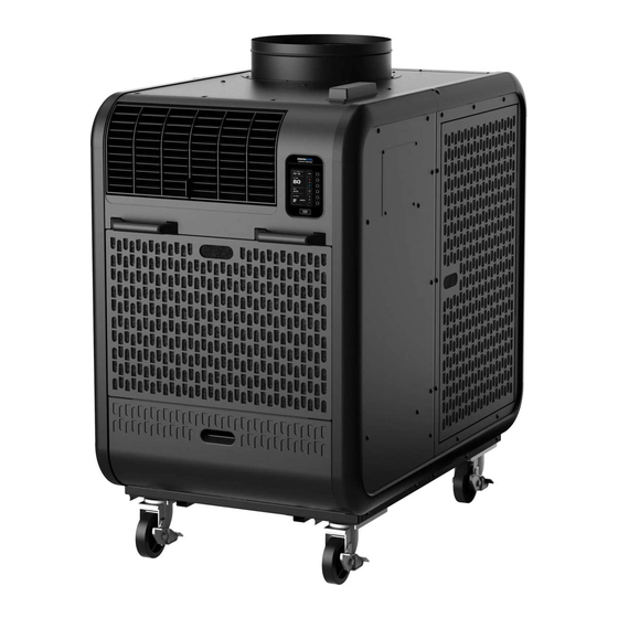
- Page 1 SERVICE MANUAL CLIMATE PRO K36...
-
Page 2: Serial Number Location
SERIAL NUMBER LOCATION 00 0000 000 Month Year Sequential Model number name © 2020 DENSO PRODUCTS AND SERVICES AMERICAS, INC. All rights reserved. MovinCool® and Climate Pro® are registered trademarks of DENSO Corporation. -
Page 3: Table Of Contents
TABLE OF CONTENTS SERIAL NUMBER LOCATION ································································2 SAFETY PRECAUTIONS ········································································5 CONSTRUCTION ···················································································7 Dimensions ········································································································· 7 Names of Parts ·································································································· 8 Internal Structure ······························································································ 9 SPECIFICATIONS ················································································· 10 Technical Specifications ···················································································10 Characteristics at 208V ···················································································12 Characteristics at 230V ···················································································13 SERVICE INFORMATION ····································································· 14 Machine Status ·································································································14 Machine Records ······························································································15 TROUBLESHOOTING ··········································································... - Page 4 TABLE OF CONTENTS INSPECTION OF PARTS ·······································································67 Capacitor ·········································································································· 67 Drain Switch ····································································································· 67 Fan Motor (Evaporator) ···················································································68 Fan Motor (Condenser) ···················································································69 Compressor ······································································································ 70 Thermistor ········································································································· 71 High Pressure Switch ······················································································· 71 REFRIGERATION SYSTEM REPAIR ······················································72 Brazing ·············································································································· 72 Replacement of Refrigeration Cycle Parts ···················································...
-
Page 5: Safety Precautions
SAFETY PRECAUTIONS To reduce the risk of injury or malfunction, read “Safety Precautions” carefully before servicing the unit. The seriousness is classified by the following indicators. Indicates a hazardous situation which, if not avoided, could WARNING result in death or serious injury. Indicates a hazardous situation which, if not avoided, could CAUTION result in minor or moderate injury, damage to the unit or its... - Page 6 Failure to do so may lead to loss of vision or burns. Work in a well-ventilated area while brazing. Failure to do so may lead to explosion, fire or lack of oxygen. Use official MovinCool parts for servicing. Non-genuine accessories or incomplete installation may cause fire, electric shock or water leaks.
-
Page 7: Construction
CONSTRUCTION Dimensions DIA. 15.7 21.8 34.7 48.7 30.6 Unit: inch... -
Page 8: Names Of Parts
Names of Parts Condenser Air Outlet Flange Antenna Control Panel Cold Air Outlet Grill Service Panel for Communication Module Front Handle Evaporator Condenser Air Inlet Panel Air Inlet Panel Drain Tank Cover Service Panel for Pump Top Panel Upper Rear Panel Rear Handle Logo Side Panel Power Cord Holder... -
Page 9: Internal Structure
Internal Structure Condenser Fan Drain Pan Drain Tank Control Box Compressor Communication Module Evaporator Condenser Fan Motor (Condenser) Evaporator Fan Fan Motor Capillary Tube (Evaporator) Drain Switch... -
Page 10: Specifications
SPECIFICATIONS Technical Specifications ITEM SPECIFICATIONS Electronic Features Control Programmable Cooling Capacity * Total Capacity 36,000 Btu/h Power Requirement 208/230V, 1Phase, 60Hz Total Power Consumption * 4.3/4.3 kW Current Consumption * 21.6/19.9 amps Electrical Characteristics Starting Current 105 amps Recommended Fuse Size 30 amps Min. - Page 11 Technical Specifications ITEM SPECIFICATIONS Internal Overload Relay for 257°F ± 9°F (125°C ± 5°C) Compressor 91 amps Safety Device Anti-Freezing Thermostat for On: 60°F ± 1.8°F (16°C ± 1°C) Evaporator Off: 27°F ± 1.8°F (-3°C ± 1°C) No voltage contact input Fire Alarm lnput Contact resistance: less than 100 ohm...
-
Page 12: Characteristics At 208V
Characteristics at 208V <Cooling Capacity Curve> <Cool Air Temperature Difference Curve> 23.4(13) 21.6(12) 19.8(11) 18.0(10) 16.2(9) 14.4(8) 12.6(7) 10.8(6) 95(35) 9.0(5) 86(30) 7.2(4) 77(25) 68(20) Relative Humidity (%) (10) (15) (20) (25) Wet Bulb Temp. °F (°C) <Power Consumption Curve> <Current Consumption Curve>... -
Page 13: Characteristics At 230V
Characteristics at 230V <Cooling Capacity Curve> <Cool Air Temperature Difference Curve> 23.4(13) 21.6(12) 19.8(11) 18.0(10) 16.2(9) 14.4(8) 12.6(7) 10.8(6) 95(35) 9.0(5) 86(30) 7.2(4) 77(25) 68(20) Relative Humidity (%) (10) (15) (20) (25) Wet Bulb Temp. °F (°C) <Power Consumption Curve> <Current Consumption Curve>... -
Page 14: Service Information
SERVICE INFORMATION Machine Status The status of functional parts can be displayed while the unit is running. HOME > MENU > SERVICES > MACHINE INFORMATION > MACHINE STATUS CLIMATE PRO MON 12:00 PM MACHINE BACK STATUS 75 F Multi-function buttons CTS1 54 F CTS2... -
Page 15: Machine Records
Machine Records The history of connection time, compressor operating time, defrosting time, fan operating time, and self-diagnostic codes are displayed while the unit is running. HOME > MENU > SERVICES > MACHINE INFORMATION > MACHINE RECORDS CLIMATE PRO MON 12:00 PM MACHINE BACK RECORDS... -
Page 16: Troubleshooting
TROUBLESHOOTING Initial Inspection Before troubleshooting, the following inspection should be performed. 1. Check the voltage of the power source. 208/230 V, 1 Phase, 60 Hz 2. Check the operation and condition of the fuse or circuit breaker in the power source. 3. -
Page 17: Self-Diagnostic Codes
Self-Diagnostic Codes When a self-diagnostic code is displayed on the LCD, the unit stops operation, relay contact RL07 for terminal OS-1 and OS2 is closed. CODE CONDITION POSSIBLE CAUSE SOLUTION Alarm device connected to 1. Check FA-1, FA-2 connection Alarm device 1 is FA-1 and FA-2 of terminal 2. - Page 18 Self-Diagnostic Codes When a self-diagnostic code is displayed on the LCD, the unit stops operation, relay contact RL07 for terminal OS-1 and OS2 is closed. CODE CONDITION POSSIBLE CAUSE SOLUTION Condensate pump stops due 1. Remove blockage or kinks from drain to kinks and/or blockage or line, or re-route drain line improper routing of drain line...
-
Page 19: Troubleshooting Chart
Troubleshooting Chart PROBLEM POSSIBLE CAUSE SOLUTION Check and fix power Power failure supply and connection Ground fault protective breaker is tripped Reset breaker No display on LCD screen Defective ground fault protective breaker Repair or replace breaker Unit does not operate LCDI Power cord is tripped Reset power cord... - Page 20 Troubleshooting Chart PROBLEM POSSIBLE CAUSE SOLUTION Operating near minimum or maximum of Review room environment operating temperature range Dirt in indoor or outdoor heat exchanger Clean heat exchanger Poor cooling Air volume Compressor Frosting on the refrigerant line caused due Service refrigeration performance normal...
- Page 21 Troubleshooting Chart PROBLEM POSSIBLE CAUSE SOLUTION Cracks in drain pan Replace drain pan Drain hose is blocked or damaged Unblock or repair drain Water leaking from unit (Optional drain pump) hose Reversed air flow from drain hole due to Clean air filters excessive negative pressure inside of unit Fan interference Adjust interfering section...
-
Page 22: Inspection Before Disassembly
Inspection Before Disassembly 1. Inspection of plate fins on heat exchangers Remove air filters and check plate fins for any dirt, dust, lint, or debris that may cause insufficient cooling performance. If necessary, clean the plate fins. Plate Fins 2. Inspection of cooling capacity performance Measure the difference in air temperature between the inlet of the evaporator and the cool air vent. -
Page 23: Disassembly
• Use genuine MovinCool parts for servicing. Non-genuine parts may cause fire, electric shock or water leaks. • Disconnect power supply from the unit before performing any service. Beware that some residual voltage may remain in the unit immediately after the power is disconnected. -
Page 24: Structure Parts
Structure Parts Front Panel Control Panel Louver Condenser Side Panel Antenna Wire Frame Top Panel Evaporator Filter Panel Condenser Filter Evaporator Filter Condenser Filter Panel Wire Frame Drain Tank Frame Drain Tank Front Handle Drain Tank Cover Upper Rear Panel Drain Tank Base Plate Condensate Float Main Rear Panel... -
Page 25: Removal Of Panels
Removal of Panels 1. Open the drain tank cover and remove the condensate float and two tanks. 2. Remove the front filter panel. 3. Open the side filter panel and remove it by lifting upward. - Page 26 Removal of Panels 4. Remove the ten (10) M4 x L10 screws and then remove the service panel. Screw (10) M4 x L10 5. Loosen the bottom two (2) screws and remove the other ten (10) M6 x L12 screws, and then remove the main rear panel.
- Page 27 Removal of Panels 7. Remove the ten (10) M6 x L12 screws from the side and the three (3) M6 x L12 screws from the rear. Screw (10) M6 x L12 Screw (3) M6 x L12 8. Remove the two (2) M4 x L10 screws from the Bumper Connection bumper connections, and then remove one half of the logo side panel.
- Page 28 Removal of Panels 10. Remove the nine (9) M6 x L12 screws from the side and the three (3) M6 x L12 screws from the rear. Screw (9) M6 x L12 Screw (3) M6 x L12 11. Remove the six (6) M4 xL10 screws. Screw (6) M4 x L10 Bumper Connection...
- Page 29 Removal of Panels 13. Loosen the bottom two (2) screws and remove the other ten (10) M6 x L12 screws, and then remove the other half of the condenser side panel. Screw (10) M6 x L12 Loosen Screw (2) 14. Disconnect CN1 and CN2 connectors from the control board. 15.
- Page 30 Removal of Panels 16. Remove the four (4) M4 x L10 screws from the top, and the four (4) M6 x L12 screws from the bottom of the upper rear panel. Next remove the upper rear panel. Screw (4) M4 x L10 Upper Rear Panel Screw (4) M6 x L12...
- Page 31 Removal of Panels 18. Remove the seven (7) M6 x L12 screws and remove the top panel. Screw (7) M6 x L12 Top Panel 19. Remove the four (4) M6 x L12 screws and remove the lower rear panel. Lower Rear Panel Screw (4) M6 x L12...
-
Page 32: Removal Of Louver
Removal of Louver 1. Loosen the bottom two (2) screws and remove the two (2) M4 x L10 screws. Next move the service panel for Communication Module upward and remove it from the condenser side panel. Screw (2) M4 x L10 Loosen Screw (2) Control Panel 2. - Page 33 Removal of Louver 4. Remove the five (5) M6 x L12 screws as shown from the logo side panel. Screw (5) M6 x L12 Logo Side Panel 5. a) Loosen the two (2) screws located in the lower side of the upper front panel. CAUTION •...
- Page 34 Removal of Louver 6. Remove the four (4) M4 x L8 screws from the upper front panel. Screw (4) M4 x L8 7. Remove the two (2) M4 x L8 countersunk screws as shown, and remove the louver with the two (2) support plates.
-
Page 35: Removal Of Handles
Removal of Handles 1. Front Handles a) Remove the front filter panel. b) Remove the two (2) nuts on the back of the handle as shown and remove the handle. Nut (2) Nut (2) - Page 36 Removal of Handles 2. Rear Handles a) Remove the six (6) M4 x L8 countersunk screws and then remove the logo panel. Countersunk Screw (6) M4 x L8 b) Remove the ten (10) M6 x L12 screws from the side and the six (6) M6 x L12 screws from the rear.
- Page 37 Removal of Handles d) Remove the two (2) nuts on the back of the handle as shown and remove the handle. Nut (2) Nut (2) CAUTION Be aware of any sharp edges to avoid injury when working on unit.
-
Page 38: Removal Of Side Panels
Removal of Side Panels The side panels can be removed without disassembling the panels or bumpers. 1. Logo Side Panel a) Remove the eighteen (18) M6 x L12 screws as shown from the logo side panel. Screw (18) M6 x L12 b) Remove the six (6) M6 x L12 screws from the rear. - Page 39 Removal of Side Panels 2. Condenser Side Panel a) Open the side filter panel and remove it by lifting upward. b) Remove the eighteen (18) M6 x L12 screws and the six (6) M4 x L10 screws as shown from the condenser side panel. Screw (6) M4 x L10 Screw (18)
-
Page 40: Removal Of Bumpers
Removal of Bumpers 1. Names of parts a) Logo side panel Logo Side Panel Assy Logo Side Panel Assy Upper Bumper Upper Bumper Connection Steel Stay Steel Stay Upper Bumper Bumper Corner Bumper Corner Steel Stay Steel Stay Side Bumper Logo Side Panel Logo Side Panel Side Bumper... - Page 41 Removal of Bumpers b) Condenser side panel Condenser Side Panel Assy Condenser Side Panel Assy Upper Bumper Connection Steel Stay Steel Stay Upper Bumper Upper Bumper Bumper Corner Bumper Corner Steel Stay Side Bumper Side Bumper Condenser Side Panel Condenser Side Panel Steel Stay Bumper Corner Lower Bumper...
- Page 42 Removal of Bumpers Logo Side Panel Assy a) Remove the three (3) M4 x L6 screws from the bumper b) Remove the three (3) M4 x L6 screws from the bumper c) Remove the three (3) M4 x L6 screws from the bumper d) Remove the two (2) M4 x L8 silver screws from the bumper e) Remove the two (2) M4 x L8 silver screws from the bumper f) Remove the whole bumper from the logo side panel...
- Page 43 Removal of Bumpers g) To disassemble the bumper, remove the six (6) M4 x L8 silver screws. Note: The steel stays can be removed from the bumpers by sliding as shown. Back Silver Screw (6) Steel Stay M4 x L8 Steel Stay Steel Stay...
- Page 44 Removal of Bumpers Logo Side Panel Assy a) Remove the two (2) M4 x L6 screws from the bumper b) Remove the two (2) M4 x L6 screws from the bumper c) Remove the three (3) M4 x L6 screws from the bumper d) Remove the two (2) M4 x L8 silver screws from the bumper e) Remove the two (2) M4 x L8 silver screws from the bumper f) Remove the whole bumper from the logo side panel...
- Page 45 Removal of Bumpers g) To disassemble the bumpers, remove the four (4) M4 x L8 silver screws. Note: The steel stays can be removed from the bumper by sliding as shown. Back Steel Stay Steel Stay Silver Screw (4) M4 x L8 Steel Stay...
- Page 46 Removal of Bumpers Condenser Side Panel Assy a) Remove the two (2) M4 x L6 screws from the bumper b) Remove the two (2) M4 x L6 screws from the bumper c) Remove the three (3) M4 x L6 screws from the bumper d) Remove the two (2) M4 x L8 silver screws from the bumper e) Remove the two (2) M4 x L8 silver screws from the bumper f) Remove the whole bumper from the logo side panel...
- Page 47 Removal of Bumpers g) To disassemble the bumper, remove the four (4) M4 x L8 silver screws. Note: The steel stays can be removed from the bumpers by sliding as shown. Back Steel Stay Steel Stay Steel Stay...
- Page 48 Removal of Bumpers Condenser Side Panel Assy a) Remove the three (3) M4 x L6 screws from the bumper b) Remove the three (3) M4 x L6 screws from the bumper c) Remove the three (3) M4 x L6 screws from the bumper d) Remove the two (2) M4 x L8 silver screws from the bumper e) Remove the two (2) M4 x L8 silver screws from the bumper f) Remove the whole bumper from the logo side panel...
- Page 49 Removal of Bumpers g) To disassemble the bumper, remove the six (6) M4 x L8 silver screws. Note: The steel stays can be removed from the bumpers by sliding as shown. Back Steel Stay Silver Screw (6) M4 x L8 Steel Stay Steel Stay...
-
Page 50: Removal Of Electrical Parts
Removal of Electrical Parts 1. Control box a) Remove the service panel from the logo side panel. (See step 4 on page 26) b) Remove the following number of screws and remove each electrical part from the control box. - Relay: two (2) screws - Terminal block 1: two (2) screws - Terminal block 2: two (2) screws - Compressor motor capacitor: one (1) nut... - Page 51 Removal of Electrical Parts 2. Relay Board a) Remove the six (6) supports with needle-nose pliers and remove relay board from the control box. Note: Be careful not to damage the relay board. b) Disconnect the twelve (12) connectors from the relay board. CN01 (Black) To Terminal Block 1 (T for Power)
- Page 52 Removal of Electrical Parts 3. Control Panel a) Follow step 1, 2, 3, 4, and 5 in “Removal of Louver” section on page 32 and 33. b) Remove the four (4) M4 x L8 silver screws and remove the control panel from the upper front panel.
-
Page 53: Removal Of Antenna
Removal of Antenna 1. Loosen the bottom two (2) screws and remove the two (2) M4 x L10 screws. Next move the service panel for Communication Module upward and remove it from the condenser side panel. Screw (2) M4 x L10 Loosen Screw (2) Control Panel 2. - Page 54 Removal of Antenna 3. Remove the two (2) M4 x L10 screws from underneath the top panel to detach antenna from the top panel. Note: Do not try to remove antenna wires from the antenna housing, this may cause damage to the antenna module.
-
Page 55: Removal Of Communication Module
Removal of Communication Module 1. Loosen the bottom two (2) screws and remove the two (2) M4 x L10 screws. Next move the service panel for Communication Module upward and remove it from the condenser side panel. Screw (2) M4 x L10 Loosen Screw (2) Control Panel 2. - Page 56 Removal of Communication Module 3. Remove the two (2) M4 x L10 screws from the Communication Module. Communication Module Screw (2) M4 x L10...
- Page 57 Removal of Communication Module Communication Module Hardware Description Battery Cover Reset button Mode Button Battery Cover Screws Battery ON/OFF Switch Service Cover LED Indicators Table of LED Indication LABEL NAME COLOR LED “ON” LED “OFF” LED BLINKING Power LED Working Sleeping Error NOT in...
- Page 58 Removal of Communication Module 4. Disconnect the following cable connectors: - I/F connector - GNSS connector - BLE connector - LTE2 connector - LTE1 connector LTE1 Connector BLE Connector I/F Connector GNSS Connector LTE2 Connector...
- Page 59 Removal of Communication Module 5. Battery Removal and Installation Model SC-04002-02 Battery Specification Nominal Voltage 3.7V Nominal Capacity 2500 mAh Note: Before disconnecting the battery, place the battery switch to “OFF” position. (See section 6, Set Communication Module to Operate by Internal Battery) a) Remove two screws from battery cover.
- Page 60 Removal of Communication Module 6. Set Communication Module to Operate by Internal Battery Service Cover a) Remove service cover b) Set the battery switch to “ON” position. Battery ON/OFF Switch c) Wait for network to connect, after connection L LED (orange) lights up. LEDs lights up for 3 minutes then go to sleep mode (all LEDs turn off to save battery life) “L”...
- Page 61 Removal of Communication Module 7. Reset Communication Module a) Remove service panel b) Use a nylon or wooden tool to press RESET button of the communication module CAUTION • Do not use sharp objects to press the reset button as it may damage the control panel. c) “P”...
-
Page 62: Removal Of Blower Assembly
Removal of Blower Assembly Ring Evaporator Fan Evaporator Fan Casing Fan Motor (Condenser) Extension Shaft Motor Stay Ring Motor Stay Fan Motor (Evaporator) Frame Sub-Assy Condenser Fan Casing Condenser Fan Fan Cover... - Page 63 Removal of Blower Assembly 1. Remove the four (4) M4 x L10 screws and remove the cover of the condenser fan casing. Condenser Fan Casing Screw (4) M4 x L10 2. Loosen the set screw of the condenser fan with a hex key. Set Screw Note: When reinstalling the condenser fan, fasten the set screw at the torque of 10 ±...
- Page 64 Removal of Blower Assembly 4. Loosen the set screw with a hex key and remove the extension shaft. Set Screw Extension Shaft Note: When reinstalling the extension shaft, fasten the set screw at the torque of 6 ± 0.6 ft·lbf (4.4 ± 0.4 N·m). 5.
- Page 65 Removal of Blower Assembly 7. Remove CN20 connector (for condenser fan motor) and CN21 connector (for evaporator fan motor) from the relay board. Relay Board 8. Remove the four (4) nuts, and then remove the condenser fan motor assembly. Nut (4) 9.
- Page 66 Removal of Blower Assembly 10. Remove the four (4) nuts and remove the evaporator fan motor assembly. Nut (4) 11. Loosen the set screw and remove the evaporator fan. Note: When reinstalling the evaporator fan, fasten the set screw at the torque of 10 ± 1 ft·lbf Set Screw (14 ±...
-
Page 67: Inspection Of Parts
INSPECTION OF PARTS Capacitor 1. Ohmmeter method Set the ohmmeter to the 10M range. Place the two probes against the two terminals of the capacitor. At first, the ohmmeter should indicate a small value, and then the reading should gradually increase towards infinity. This indicates that the capacitor is charging. If the reading indicates infinity immediately (open) or the ohmmeter fails to move from 0 (short), replace the capacitor. -
Page 68: Fan Motor (Evaporator)
Fan Motor (Evaporator) Check the resistance values across the two pins listed in the table below on the 8-pin fan motor connector with an ohm-meter. If the measured values are outside of the acceptable values, then replace the fan motor. 8-pin connector 8 7 6 5 Connector Pin No. -
Page 69: Fan Motor (Condenser)
Fan Motor (Condenser) Check the resistance values across the two pins listed in the table below on the 7-pin fan motor connector with an ohm-meter. If the measured values are outside of the acceptable values, then replace the fan motor. 7-pin connector 7 6 5 Connector Pin No. -
Page 70: Compressor
Compressor 1. Disconnect the wire connector. Wire Connector Compressor Motor 2. Compressor Motor Check resistance across the terminals: Between terminals at 77 °F (25 °C) - R-C Approx. 0.56 ohm - C-S Approx. 1.25 ohm - S-R Approx. 1.81 ohm If the measured resistance is not equal to these standard values, replace the compressor. -
Page 71: Thermistor
Thermistor Check the resistance value across the 2 pins of 2- pin thermistor connector with an ohm-meter. The thermistors of RTS (Evaporator air inlet thermistor) and CTS1 (Evaporator pipe thermistor) are the same type. If the measured value is outside of the thermistor specification, replace the thermistor. -
Page 72: Refrigeration System Repair
REFRIGERATION SYSTEM REPAIR Brazing If a problem with refrigerant system is found, replace or repair the relevant part. After replacing any part, all connections must be brazed. WARNING To avoid burns, lack of oxygen or unit malfunction: • Brazing must be performed by a qualified technician only. •... - Page 73 Brazing 4. Use of dry nitrogen gas The brazing flame oxidizes the inner surface of the pipe. To prevent this, introduce dry nitrogen gas from the pinch-off tube of the refrigeration cycle at a rate of 0.27 gal/min (1 L/min); adjust with the flow regulator.
-
Page 74: Replacement Of Refrigeration Cycle Parts
Replacement of Refrigeration Cycle Parts The parts of refrigeration system are connected with copper tubes by brazing each connection. Evaporator Condenser Capillary Tube Condenser Inlet Pipe High Pressure Switch Evaporator Outlet Pipe Condenser Outlet Pipe Evaporator Pipe Compressor Compressor Discharge Pipe Compressor Suction Pipe... - Page 75 Replacement of Refrigeration Cycle Parts Before replacing the parts, recover the refrigerant using standard recovery procedures and equipment. When recovering the refrigerant, use the pinch-off tubes on the low pressure side (tube 1) and high pressure side (tube 2) as shown. To prevent oxidation, introduce dry nitrogen gas from the pinch-off tube at a rate of 0.27 gal/min (1 L/min);...
-
Page 76: Charging The System With R-410A Refrigerant
Charging the System with R-410A Refrigerant Prepare the following items: - Gauge manifold - Vacuum pump - R-410A refrigerant cylinder (Use a max of 90% of the initial weight) - Scale - Safety goggles - Heavy-duty work gloves WARNING When handling refrigerant, the following precautions should always be observed. Failure to do so may cause explosion, fire, loss of vision, lack of oxygen, burns, injury or unit malfunction. - Page 77 Charging the System with R-410A Refrigerant 1. Connection of gauge manifold Process Tube Fitting a) Remove the crushed end of the pinch- Charging Hose off tube on the high pressure side of the Side refrigerant cycle with a pipe cutter. Refrigerant b) Connect the process tube fitting to the Cycle Side...
- Page 78 Charging the System with R-410A Refrigerant WARNING Avoid working near flammable materials. Working near flammable materials may cause explosion or fire. Refrigerant may generate toxic gas if it comes into contact with an open flame or heated metal. 4. Checking gas leak Valve Setting a) Remove the charging hose from the Closed...
- Page 79 Charging the System with R-410A Refrigerant 6. Checking gas leak Valve Setting a) Remove the charging hose from the vacuum Closed Closed pump and connect it to the refrigerant Air Purging cylinder. Open Valve b) Loosen the nut on the gauge manifold side of the charging hose and open the valve of the refrigerant cylinder.
-
Page 80: Reassembly
REASSEMBLY Reassemble the unit in the reverse order of removal. The following parts require special care in reassembling the unit. Wiring Diagram Perform all wiring or rewiring as referenced in the wiring diagram. AC208/230V 60Hz IOLC CN02 CN01 CN20 CN21 RL01 RL04 CN10... -
Page 81: Compressor Mounting
Compressor Mounting 1. Install the four (4) cushions and collars on the bolts . 2. Mount the compressor in the unit. 3. Insert the four (4) nuts and fasten at the torque of 8.3 ± 2.1 ft·lbf (11.3 ± 2.9 N·m) Nut (4) Collar (4) Cushion (4) -
Page 82: Bumpers
Bumpers Logo side panel bumpers a) The steel stays have three different markings to identify which stay is used for which bumper. Insert the steel stays into the bumpers by checking the orientation of the markings as shown. b) Tighten the six (6) M4 x L8 silver screws to assemble the seven bumpers. Back Silver Screw (6) Steel Stay... - Page 83 Bumpers Logo side panel bumpers a) The steel stays have three different markings to identify which stay is used for which bumper. Insert the steel stays into the bumpers by checking the orientation of the markings as shown. b) Tighten the four (4) M4 x L8 silver screws to assemble the five bumpers. Back Steel Stay Screw (4)
- Page 84 Bumpers Condenser side panel bumpers a) The steel stays have three different markings to identify which stay is used for which bumper. Insert the steel stays into the bumpers by checking the orientation of the markings as shown. b) Tighten the four (4) M4 x L8 silver screws to assemble the five bumpers. Back Screw (4) M4 x L8...
- Page 85 Bumpers Condenser side panel bumpers a) The steel stays have three different markings to identify which stay is used for which bumper. Insert the steel stays into the bumpers by checking the orientation of the markings as shown. b) Tighten the six (6) M4 x L8 silver screws to assemble the seven bumpers. Back Silver Screw (6) M4 x L8...
-
Page 86: Data Privacy Disclosure
DATA PRIVACY DISCLOSURE Tracking of Machine Operation Data This Unit is equipped with an embedded module that collects and transmits to us data on the Unit’s operational performance (“Machine Operation Data”), including 1. Hours of operation 2. Control Panel settings 3. - Page 87 CONSUMER RIGHT TO WITHDRAW CONSENT If you no longer wish to consent to our use, collection and disclosure of Machine Operation Data, you may contact us at 1-800-264-9573 or www.movincool.com and we will disable the Machine Operation Data tracking module.
- Page 88 DENSO PRODUCTS AND SERVICES AMERICAS, INC. Long Beach, CA 90810 www.movincool.com First Edition: July 2020 P/N: SVM09-00...
Need help?
Do you have a question about the CLIMATE PRO K36 and is the answer not in the manual?
Questions and answers