Table of Contents
Advertisement
Quick Links
Advertisement
Table of Contents

Subscribe to Our Youtube Channel
Related Manuals for Kendal Lighting AC6842B


Summary of Contents for Kendal Lighting AC6842B
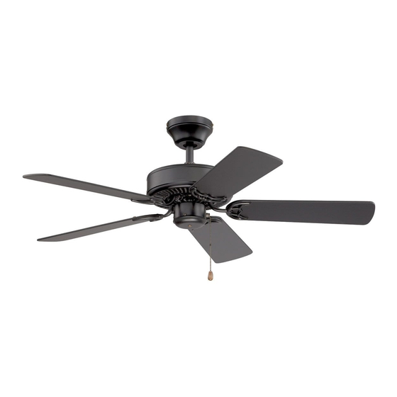
- Page 1 (MODEL NO.: AC6842B, AC6852B, AC6952B)
-
Page 2: Table Of Contents
TABLE OF CONTENTS Safety Tips -----------------------------------------------------------------------------------2 Unpacking Your Fan ----------------------------------------------------------------------3 Material Required ---------------------------------------------------------------------------4 Electrical Outlet box------------------------------------------------------------------------4 Install Mounting Bracket------------------------------------------------------------------5 Installing the Fan-----------------------------------------------------------------------------6 Electrical connections----------------------------------------------------------------------9 Blade Attachment---------------------------------------------------------------------------10 Installing Light kit---------------------------------------------------------------------------11-14 Operation--------------------------------------------------------------------------------------15 Maintenance----------------------------------------------------------------------------------16 Trouble Shooting---------------------------------------------------------------------------17 Part List----------------------------------------------------------------------------------------18 Page 1... -
Page 3: Safety Tips
SAFETY TIPS TABLE OF CONTENTS To avoid possible electric shock, turn off the electricity at the main fuse box or circuit panel before you begin the fan installation or before servicing the fan or installing accessories. CAUTION: READ ALL INSTRUCTIONS AND SAFETY INFORMATION CAREFULLY BEFORE INSTALLING YOUR FAN AND SAVE THESE INSTRUCTIONS. -
Page 4: Unpacking Your Fan
UNPACKING YOUR FAN SAFETY TIPS Unpack your fan and check the contents. Do not discard the carton. If warranty replacement or repair is ever necessary the fan should be returned in original packaging. Remove all parts and hardware. Do not lay motor housing on its side: the decorative casting may shift. -
Page 5: Material Required
TOOLS AND MATERIALS REQUIRED ELECTRICAL OUTLET BOX 1. If there is an existing outlet box, ensure it is clearly marked” Suitable For Fan Support”. If not, it must be replaced with an approved one. 2. Secure the outlet box (or make sure the existing box is secured) directly to the building structure. -
Page 6: Install Mounting Bracket
INSTALL MOUNTING BRACKET 1. To avoid possible electrical shock, be sure electricity is turned off at the main power panel before wiring. All wiring must be in accordance with National and Local Electrical Codes, and the ceiling fan must be grounded as a precaution against possible electrical shock. 2. -
Page 7: Installing The Fan
INSTALLING THE FAN SELECT TYPE OF INSTALLATION HANG DOWN STYLE 1 Slide the canopy on the downrod(Fig.6) Thread the power leads from the fan through the canopy and downrod. Take extra care not to pull on power wires. Damage and loose connections could result from any abnormal pressure on these wires. Set downrod into downrod collar yoke. - Page 8 SET SCREW SET SCREW Tighten motor set screw. Check the strength of this connection (pre-tightened at factory) by holding the motor housing in position and turning the downrod counter clockwise. If this connection slips, retighten motor setscrew and locknut. Follow the same procedures as mentioned above for downrod setscrew.
- Page 9 HUGGER STYLE 1. Put 2 screws in the hanger bracket. Leaving them partially out. (Fig. 9.1). 2. Remove three of the six screws and lock washers (every other one) from the top housing (Fig. 9.2) 3. Place the ceiling canopy over the collar on the top of the motor housing. Align the mounting holes with the holes in the motor and fasten, using the three screws and lock washers which are removed in Step 2 (Fig.
-
Page 10: Electrical Connections
ELECTRICAL CONNECTIONS Four wires are connected to the top of the fan. Black: ” Hot” Power/Live for the fan Blue: “ Hot” Power/ Live for the light kit White: “Common”/Neutral for the fan and the light kit Green/Green & Yellow: “Ground” /Earth wire If the fan and light are connected to the same circuit, the black and blue wires should be connected together to the black wire in the ceiling using a wire nut to make the connection. -
Page 11: Blade Attachment
BLADE ATTACHMENT Place screw through the blade and start the screw into the blade arm repeat this procedure without tightening the screw until all 3 screws have been started into the blade arm (Fig.11). As most fan use concealed screw blades arms, screws may not go through the whole blade arms. - Page 12 INSTALLING GENERAL TURTLE LIGHT KIT (OPTIONAL) Locate two wires in the switch housing (white and blue labeled “for light”). Connect them to the light kit wire connectors (Fig. 12) White to white Blue to blue Secure all splices with electrical tape to prevent connectors from vibrating loose during fan operation.
- Page 13 INSTALLING DISC BOWL LIGHT KIT(OPTIONAL) Remove switch housing screws and then remove bottom cap of switch housing shell on fan. Locate two wires in the switch housing (white and blue labeled “for light”). Connect them to the light kit wire connectors. White to white Blue to blue Secure those wires with wire nuts in the fan.
-
Page 14: Installing Light Kit
INSTALLING DISC LIGHT KIT (OPTIONAL) You may purchase a fan with Light Pan instead of cluster light kit mentioned above. For any kind of light kit, you should complete the blade installation before attaching this light kit assembly. REMEMBER to discount the main power before installing the light kit by removing the fuse or circuit at the electrical panel box The whole light kit assembly includes the above parts. - Page 15 INSTALLING BOWL LIGHT KIT (OPTIONAL) Remove switch housing screws and then remove bottom cap of switch housing shell on fan. Swtich Housing Scoket Light kit Fixture Figure 12.1 Locate two wires in the switch housing (white and blue labeled “for light”). Connect them to the light kit wire connectors (Fig.
-
Page 16: Operation
OPERATI ON Restore electrical power by turning on the electricity at the main fuse box. Turn on the wall switch. Your fan has two controls on the switch housing NOTE: ON FANS WITH 3 SPEEDS: 1 Pull-High 2. Pull-Medium 3. Pull-Low 4 .Pull-Off Turn off and let fan stop before changing setting of the reverse slide switch. -
Page 17: Maintenance
MAINTENANCE The fan natural movements may cause some connections to work loose. A clicking or rattling noise is a certain sign of loosening screws. Check the support connections, brackets and blade attachment twice a year, and tighten all screws as necessary. Make sure all screws attaching the glass screws are tightened. Clean your fan periodically. -
Page 18: Trouble Shooting
TROUBLE SHOOTING MAINTENANCE FAN DOES NOT START Check all fuses or circuit breakers. Replace if MISSING. Turn off electrical power and check all wire connections to fan and in switch housing. Make sure pull chain switch is on, and reverse slide switch is up or down, not in the middle. -
Page 19: Part List
If the above does not eliminate the wobble, clip a balancing kit on any one of blade about the middle of blade edge. Let fan run. If it is still wobbling, stop the fan, and change the location. Repeating this procedure on the remaining blades until the wobble is removed. - Page 22 Afin de réduire les risques de feu, de décharge électrique ou de blessure, fixez l'appareil à une boîte de sortie pouvant supporter un ventilateur de 15,9 kg (35 lb) ou moins, et utilisez les vis d'installation fournies avec la boîte de sortie. La plupart des boîtes de sortie utilisées pour l'installation d'un luminaire ne sont pas conçues pour supporter un ventilateur et doivent être remplacées.
Need help?
Do you have a question about the AC6842B and is the answer not in the manual?
Questions and answers