Table of Contents
Advertisement
Quick Links
This user's guide describes the characteristics, operation, and use of the TPS65218 evaluation module
(EVM). The TPS65218EVM is a fully assembled platform for evaluating the performance of the TPS65218
power management device. This document includes schematic diagrams, a printed-circuit-board (PCB)
layout, and bill of materials (BOM).
...................................................................................................................
1
2
2.1
2.2
2.3
.......................................................................................................................
3
.....................................................................................................................
4
5
..........................................................................................................................
6
.......................................................................................................................
7
7.1
7.2
8
........................................................................................................................
9
1
2
3
4
5
6
7
8
9
....................................................................................................................
10
11
....................................................................................................................
12
13
14
1
2
3
4
Bill of Materials
Microsoft, Windows are registered trademarks of Microsoft Corporation.
SLVUAA6 - November 2014
Submit Documentation Feedback
................................................................................................................
..............................................................................................................
......................................................................................................
........................................................................................................
...................................................................................
..........................................................................................
.............................................................................................................
..........................................................................................................
................................................................................................
......................................................................................................
..........................................................................................................
............................................................................................................
...................................................................................................
.........................................................................................................
..........................................................................................
......................................................................................................
...............................................................................................................
................................................................................................................
..................................................................................................
................................................................................................
.....................................................................................................
.........................................................................................................
.............................................................................................................
Copyright © 2014, Texas Instruments Incorporated
Contents
..................................................................
List of Figures
List of Tables
User's Guide
SLVUAA6 - November 2014
TPS65218EVM
TPS65218EVM
2
2
2
2
2
3
4
5
6
7
7
7
11
12
3
4
6
7
8
9
9
10
12
12
13
13
14
14
5
5
6
11
1
Advertisement
Table of Contents

Related Manuals for Texas Instruments TPS65218EVM


Summary of Contents for Texas Instruments TPS65218EVM
-
Page 1: Table Of Contents
This user’s guide describes the characteristics, operation, and use of the TPS65218 evaluation module (EVM). The TPS65218EVM is a fully assembled platform for evaluating the performance of the TPS65218 power management device. This document includes schematic diagrams, a printed-circuit-board (PCB) layout, and bill of materials (BOM). -
Page 2: Introduction
A DC power supply capable of delivering up to 5 V and 3 A, and a coin cell battery or separate 3-V power supply for the backup supplies. TPS65218EVM SLVUAA6 – November 2014 Submit Documentation Feedback Copyright © 2014, Texas Instruments Incorporated... -
Page 3: Evm Kit
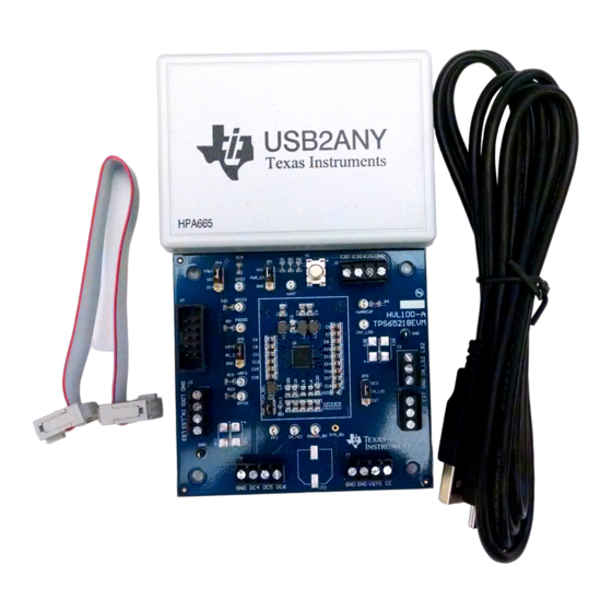
USB to USB micro cable • 10-pin ribbon cable • 30-pin ribbon cable Note: The 30-pin ribbon cable is not required for the TPS65218EVM. Figure 1. TPS65218 EVM Kit SLVUAA6 – November 2014 TPS65218EVM Submit Documentation Feedback Copyright © 2014, Texas Instruments Incorporated... -
Page 4: Schematic
Schematic www.ti.com Schematic Figure 2 illustrates the schematic for this EVM. Figure 2. TPS65218 EVM Schematic TPS65218EVM SLVUAA6 – November 2014 Submit Documentation Feedback Copyright © 2014, Texas Instruments Incorporated... -
Page 5: Terminal Block, Test Point, And Jumper Descriptions
Output indicating power source for battery backup supplies PGOOD_BU Power good for backup supplies Test points are not designed to carry current, they are intended for measuring voltage. SLVUAA6 – November 2014 TPS65218EVM Submit Documentation Feedback Copyright © 2014, Texas Instruments Incorporated... -
Page 6: Setup
VSYS application. Setup Figure 3 displays an example setup for using the TPS65218 EVM. DCDC1 Load USB2ANY 5V Supply 3V Supply Figure 3. TPS65218 EVM Setup TPS65218EVM SLVUAA6 – November 2014 Submit Documentation Feedback Copyright © 2014, Texas Instruments Incorporated... -
Page 7: Software
Reading a Register: Click on the desired register name within the Register Map, then click the “Read Register” button. Alternatively, all registers can be read simultaneously by clicking the “Read All” button. Figure 4. Reading a Register SLVUAA6 – November 2014 TPS65218EVM Submit Documentation Feedback Copyright © 2014, Texas Instruments Incorporated... -
Page 8: Writing A Register
Alternatively, input the desired value into the text field under Write Data then click the button “Write Register”. Figure 5. Writing a Register TPS65218EVM SLVUAA6 – November 2014 Submit Documentation Feedback Copyright © 2014, Texas Instruments Incorporated... -
Page 9: Simulate Communication
EVM, be sure the “Simulate Communication” box is left unchecked. Figure 6. Simulate Communication Password protection: Automatically enters password when writing to password-protected registers. Figure 7. Password protection SLVUAA6 – November 2014 TPS65218EVM Submit Documentation Feedback Copyright © 2014, Texas Instruments Incorporated... -
Page 10: Saving Register Configurations
Software www.ti.com “Load Config.” and “Save Config” Buttons: The register settings can be saved and loaded at a later time. Figure 8. Saving Register Configurations TPS65218EVM SLVUAA6 – November 2014 Submit Documentation Feedback Copyright © 2014, Texas Instruments Incorporated... -
Page 11: Bill Of Materials
R19, R20, R21 R3, R5, R7, R8, Resistor R11, R23, R24 R13–R18 Resistor Resistor R25, R26 Resistor 4.7K PMIC RSL (S-PQFP-N48) 0.4 Texas Instruments TPS65218 pitch SLVUAA6 – November 2014 TPS65218EVM Submit Documentation Feedback Copyright © 2014, Texas Instruments Incorporated... -
Page 12: Layout
Layout www.ti.com Layout Figure 9 through Figure 14 illustrate the PCB layouts for the evaluation module. Figure 9. Top Layer Silkscreen Figure 10. Top Layer TPS65218EVM SLVUAA6 – November 2014 Submit Documentation Feedback Copyright © 2014, Texas Instruments Incorporated... -
Page 13: Ground Plane
Layout www.ti.com Figure 11. Ground Plane Figure 12. Mid Layer SLVUAA6 – November 2014 TPS65218EVM Submit Documentation Feedback Copyright © 2014, Texas Instruments Incorporated... -
Page 14: Bottom Layer
Layout www.ti.com Figure 13. Bottom Layer Figure 14. Bottom Layer Silkscreen TPS65218EVM SLVUAA6 – November 2014 Submit Documentation Feedback Copyright © 2014, Texas Instruments Incorporated... - Page 15 STANDARD TERMS AND CONDITIONS FOR EVALUATION MODULES Delivery: TI delivers TI evaluation boards, kits, or modules, including any accompanying demonstration software, components, or documentation (collectively, an “EVM” or “EVMs”) to the User (“User”) in accordance with the terms and conditions set forth herein. Acceptance of the EVM is expressly subject to the following terms and conditions.
- Page 16 FCC Interference Statement for Class B EVM devices NOTE: This equipment has been tested and found to comply with the limits for a Class B digital device, pursuant to part 15 of the FCC Rules. These limits are designed to provide reasonable protection against harmful interference in a residential installation.
- Page 17 【無線電波を送信する製品の開発キットをお使いになる際の注意事項】 本開発キットは技術基準適合証明を受けておりません。 本製品のご使用に際しては、電波法遵守のため、以下のいずれかの措置を取っていただく必要がありますのでご注意ください。 1. 電波法施行規則第6条第1項第1号に基づく平成18年3月28日総務省告示第173号で定められた電波暗室等の試験設備でご使用 いただく。 2. 実験局の免許を取得後ご使用いただく。 3. 技術基準適合証明を取得後ご使用いただく。 なお、本製品は、上記の「ご使用にあたっての注意」を譲渡先、移転先に通知しない限り、譲渡、移転できないものとします。 上記を遵守頂けない場合は、電波法の罰則が適用される可能性があることをご留意ください。 日本テキサス・インスツルメンツ株式会社 東京都新宿区西新宿6丁目24番1号 西新宿三井ビル 3.3.3 Notice for EVMs for Power Line Communication: Please see http://www.tij.co.jp/lsds/ti_ja/general/eStore/notice_02.page 電力線搬送波通信についての開発キットをお使いになる際の注意事項については、次のところをご覧くださ い。http://www.tij.co.jp/lsds/ti_ja/general/eStore/notice_02.page SPACER EVM Use Restrictions and Warnings: 4.1 EVMS ARE NOT FOR USE IN FUNCTIONAL SAFETY AND/OR SAFETY CRITICAL EVALUATIONS, INCLUDING BUT NOT LIMITED TO EVALUATIONS OF LIFE SUPPORT APPLICATIONS.
- Page 18 Notwithstanding the foregoing, any judgment may be enforced in any United States or foreign court, and TI may seek injunctive relief in any United States or foreign court. Mailing Address: Texas Instruments, Post Office Box 655303, Dallas, Texas 75265 Copyright © 2014, Texas Instruments Incorporated...
- Page 19 IMPORTANT NOTICE Texas Instruments Incorporated and its subsidiaries (TI) reserve the right to make corrections, enhancements, improvements and other changes to its semiconductor products and services per JESD46, latest issue, and to discontinue any product or service per JESD48, latest issue.
- Page 20 Mouser Electronics Authorized Distributor Click to View Pricing, Inventory, Delivery & Lifecycle Information: Texas Instruments TPS65218EVM-100...
Need help?
Do you have a question about the TPS65218EVM and is the answer not in the manual?
Questions and answers