Table of Contents
Advertisement
Quick Links
TM-VE266FS.2690 Rev.B Page 1 Friday, November 10, 2000 2:51 PM
Operating and
R
Maintenance
Instructions
Manual
VE266FS
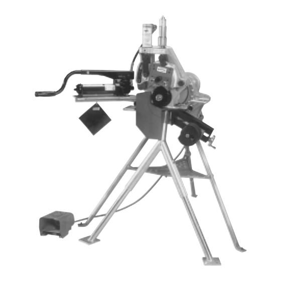
Pipe/Tubing Roll Grooving Tool
Failure to follow Instructions and warnings can result in serious personal injury.
• Before installing, operating or servicing the VE266FS tool, read this Manual and
all warning labels on the tool.
• Always wear safety glasses and foot protection.
If you need additional copies of the manual or have any questions about the safe
operation of this tool, contact Victaulic Tool Company, P.O. Box 31, Easton, PA
18044-0031, Phone: 610-559-3300.
Advertisement
Table of Contents

Related Manuals for Victaulic VE266FS


Summary of Contents for Victaulic VE266FS
- Page 1 Pipe/Tubing Roll Grooving Tool Failure to follow Instructions and warnings can result in serious personal injury. • Before installing, operating or servicing the VE266FS tool, read this Manual and all warning labels on the tool. • Always wear safety glasses and foot protection.
-
Page 2: Table Of Contents
Power Requirements..... 4 Victaulic Adjustable Pipe Stands ..26 Extension Cord Requirements ... . . 4 Stabilizer Assembly . -
Page 3: Operator Safety Instructions
OPERATOR SAFETY INSTRUCTIONS The VE266FS is designed only for roll grooving ³⁄₄ - 8" Schedule 5, 10, 40 steel, aluminum and PVC pipe, as well as 10 - 12" Schedule 5 through 20 steel, aluminum pipe and 10 - 12" Schedule 40 PVC. Also ³⁄₄ - 8" Schedule 40 stain- less steel and 10 - 12"... -
Page 4: Introduction
Series 266FS tools are semi-automated hydraulic feed tools for roll grooving of pipe to prepare it to receive Victaulic grooved pipe couplings. The standard Series VE266FS tools are supplied with grooving rolls for 1 - 12" carbon steel pipe. Rolls are marked with the size and part number and color coded for pipe material, for your convenience. -
Page 5: Tool Nomenclature
TM-VE266FS.2690 Rev.B Page 5 Friday, November 10, 2000 2:51 PM VE266FS TOOL NOMECLATURE Hydraulic Connectors Hydraulic Pipe Size Cylinder Indicator Depth Adjuster Pump Depth Valve Adjuster Lock Upper Roll Assy. Pump Upper Roll Bolt Pump Adjustable Guards Handle Power Drive... -
Page 6: Receiving Tool
TM-VE266FS.2690 Rev.B Page 6 Friday, November 10, 2000 2:51 PM VE266FS RECEIVING TOOL TOOL SETUP VE266FS tools are packed individually in sturdy containers, designed for use in reship- ping tools upon completion of the rental con- tract, when applicable. Do not connect power until instructed otherwise. - Page 7 TM-VE266FS.2690 Rev.B Page 7 Friday, November 10, 2000 2:51 PM VE266FS 4. Fully open the power drive chuck. (Consult 9. Insert the two (2) adjusting legs completely power drive manufacturer's instructions.) into the sockets of upper leg and finger tighten the hex bolts.
- Page 8 TM-VE266FS.2690 Rev.B Page 8 Friday, November 10, 2000 2:51 PM VE266FS 15. Attach the pump/pump support to left side of tool, using the two (2) hex bolts sup- plied. Tighten with a wrench. 12. Loosen hex bolts to release lower legs (2) and allow them to drop down to floor.
- Page 9 TM-VE266FS.2690 Rev.B Page 9 Friday, November 10, 2000 2:51 PM VE266FS • The power drive must be operated with a safety foot switch, as the operator will require it to operate the tool safely. If your power drive does not have a foot switch, contact power drive manufacturer.
-
Page 10: Pre-Operation Adjustments
TM-VE266FS.2690 Rev.B Page 10 Friday, November 10, 2000 2:51 PM VE266FS GROOVABLE PIPE LENGTHS The VE266FS is capable of grooving short pipe PRE-OPERATION lengths without the use of a pipe stand (see ADJUSTMENTS Table 1, on this page), or long pipe lengths up to double randoms (approximately 40 ft.), with... -
Page 11: Roll Guard Adjustment
TM-VE266FS.2690 Rev.B Page 11 Friday, November 10, 2000 2:51 PM VE266FS Example: A 20' 4" length of 10" diameter pipe is needed to finish a section and you only have 20' lengths available. Instead of roll grooving a 20' piece of pipe and a 4" piece of pipe, follow •... - Page 12 TM-VE266FS.2690 Rev.B Page 12 Friday, November 10, 2000 2:51 PM VE266FS Grooving rolls can crush or cut fingers and hands. • Loading and unloading pipe will place your hands close to the rollers. • Never groove pipe shorter than what is recommended in Table 1 on page 8.
-
Page 13: Pipe Stabilizer Adjustment
TM-VE266FS.2690 Rev.B Page 13 Friday, November 10, 2000 2:51 PM VE266FS PIPE STABILIZER ADJUSTMENT (Applies only to tools equipped with the optional stabilizer.) The Series VE266FS pipe Stabilizer (Optional) is designed to prevent pipe sway on 8" through 12" nominal IPS pipe sizes. This applies to short as well as long pipes. - Page 14 TM-VE266FS.2690 Rev.B Page 14 Friday, November 10, 2000 2:51 PM VE266FS 4. Close hand pump valve and pump upper roll down into firm contact with pipe. 5. Make sure guards are properly adjusted per the Roll Guard Adjustment Procedure on pages 11 and 12.
-
Page 15: Groove Diameter Stop Adjustment
TM-VE266FS.2690 Rev.B Page 15 Friday, November 10, 2000 2:51 PM VE266FS GROOVE DIAMETER STOP ADJUSTMENT The groove diameter stop must be adjusted for each pipe size or change in wall thickness. Groove diameter, identified as the “C” dimen- sion for each pipe size, is listed under Roll Groove Specifications, pages 32 - 38. -
Page 16: Grooving Operation
TM-VE266FS.2690 Rev.B Page 16 Friday, November 10, 2000 2:51 PM VE266FS • The “C” dimension (groove diameter) must always To reduce the risk of electric conform to specifications under Roll Groove shock, check the electrical Specifications pages 32 - 38 to ensure proper joint source for proper grounding and performance. - Page 17 TM-VE266FS.2690 Rev.B Page 17 Friday, November 10, 2000 2:51 PM VE266FS 4. Open hand pump valve by turning counter- 6. Close the hand pump valve by turning clockwise. This will allow upper roll and arm to clockwise. move to full up position.
-
Page 18: Roll Changing
TM-VE266FS.2690 Rev.B Page 18 Friday, November 10, 2000 2:51 PM VE266FS ROLL CHANGING • Always unplug power cord before changing rolls. Accidental start up of tool may result in serious personal injury. Vic-Easy Series 266FS roll grooving tools are designed for fast, easy grooving. Rolls accom- modate several pipe sizes (refer to Tool Rating 10. - Page 19 TM-VE266FS.2690 Rev.B Page 19 Friday, November 10, 2000 2:51 PM VE266FS 5. Remove nut, washer and roll and store in a 2. With a wrench, loosen (counterclockwise) clean place. and remove (thin) jam nut securing large nut on lower roll shaft.
-
Page 20: Arbor Shaft Removal Procedure
TM-VE266FS.2690 Rev.B Page 20 Friday, November 10, 2000 2:51 PM VE266FS 3. Once the stud has stopped moving the arbor 2. Pull the upper roll assembly off. Store in a outwards, pull the arbor shaft and stud assem- clean place. -
Page 21: Lower Roll - ³⁄₄ " And 1 - 1 ¹⁄₂ " Sizes
TM-VE266FS.2690 Rev.B Page 21 Friday, November 10, 2000 2:51 PM VE266FS 2. While upper roll is removed from tool, 5. Lubricate upper roll bearing. Refer to Main- inspect the roller bearing inside for contamina- tenance section for additional information. tion, proper lubrication and movement. Also inspect guards for wear and freedom of adjust- LOWER ROLL –... -
Page 22: Arbor Shaft Installation Procedure
TM-VE266FS.2690 Rev.B Page 22 Friday, November 10, 2000 2:51 PM VE266FS 3. Carefully insert the lower roll and adapter 3. Carefully insert the arbor shaft assembly assembly into the main shaft, making sure it is into the main shaft, making sure it is fully fully seated. -
Page 23: Maintenance
TM-VE266FS.2690 Rev.B Page 23 Friday, November 10, 2000 2:51 PM VE266FS • Before performing any repair or maintenance, unplug the tool from the electrical source to prevent accidental start up of tool. Failure to do so could result in death or serious personal injury. -
Page 24: Hydraulic Systems
TM-VE266FS.2690 Rev.B Page 24 Friday, November 10, 2000 2:51 PM VE266FS HYDRAULIC SYSTEMS The level of hydraulic fluid in the pump must be checked semi-annually or if pumping feels spongy. FILLING AND CHECKING 1. Open pump release valve fully by turning counterclockwise. -
Page 25: Parts Ordering Information
TM-VE266FS.2690 Rev.B Page 25 Friday, November 10, 2000 2:51 PM VE266FS AIR BLEEDING PARTS ORDERING INFORMATION When ordering parts, the following information is necessary for Victaulic to process the order and send the correct part(s). Request RP-266FS Parts Manual for detailed drawings and parts listing. -
Page 26: Accessories
TM-VE266FS.2690 Rev.B Page 26 Friday, November 10, 2000 2:51 PM VE266FS ACCESSORIES VICTAULIC ADJUSTABLE PIPE STANDS VPD752 VAPS 112 Victaulic Model 112, a portable, adjustable, The Victaulic VPD752 Power Drive can be used roller type, four-leg pipe stand for use with... -
Page 27: Troubleshooting
TM-VE266FS.2690 Rev.B Page 27 Friday, November 10, 2000 2:51 PM VE266FS TROUBLESHOOTING Problem Possible Cause Solution Pipe will not stay in Incorrect pipe positioning See “Pipe Support”. grooving rolls. on long pipes. Lower roll and pipe are not Flip switch on Power Drive to rotating clockwise. - Page 28 TM-VE266FS.2690 Rev.B Page 28 Friday, November 10, 2000 2:51 PM VE266FS TROUBLESHOOTING Problem Possible Cause Solution Pipe flare is excessive. Pipe support adjusted too See “Long Pipe Lengths”. high on long pipes. Tool is tilted forward while See “Tool Setup”.
-
Page 29: Tool Rating And Roll Selection
The following O.D. sized pipe also may be roll grooved: 3" O.D. (76.1 mm), 4¹⁄₄" O.D. (108.0 mm), 5¹⁄₄" O.D. (133.0), 5¹⁄₂" O.D. (139.7), 6¹⁄₄" O.D. (159.0 mm), 6¹⁄₂" O.D. (165.1 mm), 8" O.D. (203.2 mm) and 12" O.D. (304.8 mm). Contact Victaulic for details. -
Page 30: Rolls For Stainless Steel (Rx Rolls)
TM-VE266FS.2690 Rev.B Page 30 Friday, November 10, 2000 2:51 PM VE266FS ROLLS FOR SCHEDULE 5S AND 10S STAINLESS STEEL PIPE (RX ROLLS) – COLOR CODED SILVER 0886-3A Nominal Dimensions – Inches/ Stainless Steel Pipe † SIZE Wall Thickness Nominal Min. - Page 31 TM-VE266FS.2690 Rev.B Page 31 Friday, November 10, 2000 2:51 PM VE266FS ASTM DRAWN COPPER TUBING The VE266FS will groove the following copper tubing: 2 - 8" (54.0 - 206.4 mm) Nominal Copper Tubing Sizes ASTM B-306 Type DWV ASTM B-88 Types K, L, M...
-
Page 32: Roll Groove Specifications
TM-VE266FS.2690 Rev.B Page 32 Friday, November 10, 2000 2:51 PM VE266FS ROLL GROOVE SPECIFICATIONS STEEL PIPE AND ALL MATERIALS GROOVED WITH STANDARD AND RX ROLLS 0886-5A Dimensions – Inches/ millimeters Pipe Outside Dia. O.D. Groove Dia. – C Nom. Gasket... - Page 33 All loose paint, scale, dirt, chips, grease and rust must be removed. It continues to be Victaulic’s first recommendation that pipe be square cut. When using beveled pipe contact Victaulic for details.
-
Page 34: Steel Pipe And All Materials Grooved With "Es" Rolls
TM-VE266FS.2690 Rev.B Page 34 Friday, November 10, 2000 2:51 PM VE266FS STEEL PIPE AND ALL MATERIALS GROOVED WITH “ES” ROLLS 0886-6A Dimensions – Inches/ Pipe Outside Dia. O.D. Gasket Seat Groove Width Groove Dia. Nom. Min. SIZE Grv. Allow. Max. -
Page 35: Drawn Copper Tubing
TM-VE266FS.2690 Rev.B Page 35 Friday, November 10, 2000 2:51 PM VE266FS ASTM DRAWN COPPER TUBING 25.06-1A Pipe O.D. Dimensions – Inches/ millimeters SIZE Inches/ Grv. Width Nom. Gask. Seat Groove Dia. Grv. Depth Min. Allow. Max. Inches (ref.) Wall Thick. -
Page 36: British Standard - Bs 2871
TM-VE266FS.2690 Rev.B Page 36 Friday, November 10, 2000 2:51 PM VE266FS BRITISH STANDARD DRAWN COPPER TUBING 0981-4A Dimensions – millimeters/ Inches Actual Groove Groove Min. Outside Diameter Gasket Width Diameter Groove Allow. Max. SIZE millimeters/ Seat Depth Wall Allow. Inches Actual +0.03... -
Page 37: Din German Standard - Din 1786
TM-VE266FS.2690 Rev.B Page 37 Friday, November 10, 2000 2:51 PM VE266FS DIN STANDARD DRAWN COPPER TUBING 0981-5A Dimensions – millimeters/ Inches Actual Groove Groove Min. Outside Diameter Gasket Width Diameter Groove Allow. Max. SIZE millimeters/ Seat Depth Wall Allow. Inches Actual +0.03... -
Page 38: Australian Standard - As 1432
TM-VE266FS.2690 Rev.B Page 38 Friday, November 10, 2000 2:51 PM VE266FS AUSTRALIAN STANDARD DRAWN COPPER TUBING 0981-6A Dimensions – millimeters/ Inches Actual Groove Groove Min. Outside Diameter Gasket Width Diameter Groove Allow. Max. SIZE millimeters/ Seat Depth Wall Allow. Inches Actual +0.03... -
Page 39: Dimensions
0.330 0.406 0.375 0.688 323.9 323.9 10.3 17.4 *For reference only. The VE266FS cannot groove all schedules of steel pipe in table. ASTM DRAWN COPPER TUBING 0886-8B Nominal Wall Thickness – Inches/ SIZE Outside Type “M” Type “L” Type “K”... - Page 40 TM-VE266FS.2690 Rev.B Page 40 Friday, November 10, 2000 2:51 PM Victaulic ® Factory Representatives and Distributor Stocks Worldwide Victaulic reserves the right to change product specifications, designs and standard equipment without notice and without obligation. ® Registered Trademark of Victaulic ©...
Need help?
Do you have a question about the VE266FS and is the answer not in the manual?
Questions and answers