Table of Contents
Advertisement
Quick Links
OPERATING AND MAINTENANCE INSTRUCTIONS MANUAL
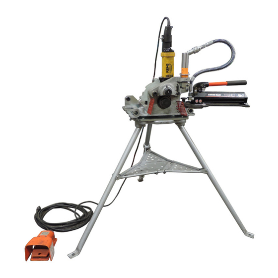
VE206 Pipe/Tubing Roll Grooving Tool
REMS AMIGO
If you need additional copies of any literature, or if you have questions concerning the safe
and proper operation of this tool, contact Victaulic, P.O. Box 31, Easton, PA 18044-0031,
Phone: 1-800-PICK VIC, E-Mail: pickvic@victaulic.com.
REV_F
†
2 COMPACT DRIVE
WARNING
Failure to follow instructions and warnings could result in death or
serious personal injury, property damage, and product damage.
• Before operating or servicing any pipe preparation tools, read all
instructions in this manual and all warning labels on the tool.
• Wear safety glasses, hardhat, foot protection, and hearing protection
while working around this tool.
• Save this operating and maintenance manual in a place accessible to
all operators of the tool.
Original Instructions
TM-VE206
*
RIDGID
700 DRIVE
† Rems Amigo is a trademark of REMS GmbH & Co KG
* Ridgid is a registered trademark of Ridgid, Inc.
TM-VE206
Advertisement
Table of Contents

Subscribe to Our Youtube Channel
Related Manuals for Victaulic VE206


Summary of Contents for Victaulic VE206
- Page 1 If you need additional copies of any literature, or if you have questions concerning the safe and proper operation of this tool, contact Victaulic, P.O. Box 31, Easton, PA 18044-0031, Phone: 1-800-PICK VIC, E-Mail: pickvic@victaulic.com.
-
Page 2: Table Of Contents
TM-VE206 / Operating and Maintenance Instructions Manual TABLE OF CONTENTS Hazard Identification ....2 Maintenance ..... . 32 Operator Safety Instructions . -
Page 3: Hazard Identification
OPERATOR SAFETY INSTRUCTIONS The VE206 Roll Grooving Tool is designed for the sole purpose of roll grooving pipe/tubing . The lessee or owner of this tool is responsible for ensuring that each operator reads this manual and fully understands the operation of this grooving tool PRIOR to working with the tool . - Page 4 . CAUTION The VE206 tool is designed ONLY for roll grooving pipe/tubing sizes, materials, and wall thicknesses specified in this manual. Inspect the equipment. Before using the tool, check moveable parts for obstructions . Verify that tool components are installed and adjusted in accordance with the "Tool Setup"...
-
Page 5: Introduction
. The standard VE206 tool is supplied with rolls for grooving 1 1/4 – 6-inch/ DN32 – DN150 carbon steel pipe . VE206 rolls are marked with the size and part number, and are color coded to identify the pipe material . For roll grooving to other specifications and materials, refer to page 37 . -
Page 6: Receiving The Tool
TM-VE206 / Operating and Maintenance Instructions Manual RECEIVING THE TOOL VE206 tools are packed individually in containers that are designed for repeated shipping . Save the original container for return shipment of rental tools . Upon receipt of the tool, verify that all necessary parts are included . If any parts are missing, contact Victaulic . -
Page 7: Power Requirements
Failure to follow these instructions could result in death or serious personal injury. POWER DRIVE REQUIREMENTS Several power drive options are available for use with the VE206, as shown in the table below . Consult the power drive manufacturer’s instructions for proper operation . -
Page 8: Tool Nomenclature
• Operate the tool only with a safety foot switch. If the tool does not contact Victaulic. contain a safety foot switch, contact Victaulic. Contact Victaulic with questions regarding the safe and proper operation of tools: Contact Victaulic with questions regarding the safe and proper operation of tools: Web: victaulic.com E-Mail: pickvic@victaulic.com Phone: 1-800-PICK-VIC... -
Page 9: Tool Dimensions And Specifications
TM-VE206 / Operating and Maintenance Instructions Manual TOOL DIMENSIONS AND SPECIFICATIONS 14.89 in/ 12.89 in/ 378 mm 327 mm 40.00 in/ 1016 mm 39.96 in/ 1015 mm 46.07 in/ 46.16 in/ 1170 mm 48.07 in/ 1172 mm 1221 mm 54.34 in/ 54.97 in/... -
Page 10: Setup Of The Stand Assembly
Failure to follow this instruction could result in death or serious personal injury. The VE206 tool is intended for field or shop setup . 1. Remove all components from the packaging, and verify that all necessary items are included . Refer to the “Receiving the Tool”... -
Page 11: Setup Of The Tool Head Assembly
TM-VE206 / Operating and Maintenance Instructions Manual SETUP OF THE TOOL HEAD ASSEMBLY WARNING • Always use proper lifting techniques when handling the tool head assembly. Failure to follow this instruction could result in personal injury. 1. Using proper lifting techniques, lift the tool head assembly by the two handles with the roll guards facing toward you, as shown . - Page 12 TM-VE206 / Operating and Maintenance Instructions Manual 3. Tighten each wing head thumb screw to secure the tool head assembly onto the stand assembly . Verify that the bolts are tightened evenly on both the left and right sides of the tool head assembly .
-
Page 13: Power Drive
Failure to follow this instruction could result in death or serious personal injury. NOTICE • The VE206 requires drive-specific mounting hardware. Verify that the power drive is compatible with the provided hardware before mounting. 1. Place the Ridgid 700 Power Drive on the back of the stand assembly . Align the tapped hole in the Ridgid 700 Power Drive’s body with the hole in the mounting bracket on the base plate . - Page 14 TM-VE206 / Operating and Maintenance Instructions Manual 5. Using a 5/16-inch hex key, tighten each set screw on the square drive adapter of the Ridgid 700 power drive . 6. Verify that the Ridgid 700 power drive is properly aligned with the tool head assembly . The edge of the tapped hole on the power drive shall lie flush against the mounting plate on the stand assembly, as shown above .
- Page 15 TM-VE206 / Operating and Maintenance Instructions Manual DANGER • To reduce the risk of electric shock, check the electrical source for proper grounding. • Before performing any maintenance on the tool, disconnect the power cord from the electrical source. Failure to follow these instructions could result in death or serious personal injury.
-
Page 16: Setup Of The Rems Amigo 2 Compact Power Drive
Failure to follow this instruction could result in death or serious personal injury. NOTICE • The VE206 requires drive-specific mounting hardware. Verify that the power drive is compatible with the provided hardware before mounting. 1. The Rems Amigo 2 Compact Power Drive shall be equipped with the stop ring (Rems No . - Page 17 TM-VE206 / Operating and Maintenance Instructions Manual 3. Plug the Rems Amigo 2 Compact Power Drive cord into a grounded electrical outlet . Refer to the power drive manufacturer’s operating manual for additional information . 4. Depress the safety foot switch . Verify that the lower roll rotates away from the operator when viewed from the front of the tool .
-
Page 18: Setup Of The Hydraulic Hand Pump
TM-VE206 / Operating and Maintenance Instructions Manual SETUP OF THE HYDRAULIC HAND PUMP The hydraulic hand pump can be installed on either the left-hand or right-hand side of the tool . 1. Place the hydraulic hand pump over one of the lifting handles on the tool head assembly . Verify that the lip on the underside of the pump’s mounting plate aligns with the edge of the lifting handle . -
Page 19: Pre-Operation Checks And Adjustments
TM-VE206 / Operating and Maintenance Instructions Manual PRE-OPERATION CHECKS AND ADJUSTMENTS Every Victaulic roll grooving tool is checked, adjusted, and tested at the factory prior to shipment . However, before operating the tool, the following checks and adjustments shall be made to ensure proper tool operation . -
Page 20: Pipe/Tubing Lengths Suitable For Grooving
TM-VE206 / Operating and Maintenance Instructions Manual PIPE/TUBING LENGTHS SUITABLE FOR GROOVING The VE206 tool is capable of grooving short pipe lengths without the use of a pipe stand . Refer to the “Short Pipe/Tubing Lengths” section on this page . -
Page 21: Long Pipe/Tubing Lengths
TM-VE206 / Operating and Maintenance Instructions Manual LONG PIPE/TUBING LENGTHS When roll grooving pipe that exceeds the maximum length shown in Table 1, a roller-type pipe stand shall be used . The pipe stand shall be capable of handling the weight of the pipe, while allowing the pipe to rotate freely . -
Page 22: Grooving Operation
TM-VE206 / Operating and Maintenance Instructions Manual GROOVING OPERATION DANGER • To reduce the risk of electric shock, check the electrical source for proper grounding. • Before operating the tool, review the “Operator Safety Instructions” section of this manual. Failure to follow these instructions could result in death or serious personal injury. - Page 23 TM-VE206 / Operating and Maintenance Instructions Manual 3. Depress the safety foot switch . Verify that the lower roll rotates away from the operator when viewed from the top of the tool . If the lower roll rotates toward the operator, see the appropriate power drive section for instructions to reverse rotation .
- Page 24 TM-VE206 / Operating and Maintenance Instructions Manual WARNING Grooving rolls can crush or cut fingers and hands. • Before making any tool adjustments, always disconnect the power cord from the electrical source. • Loading and unloading pipe will place your hands close to the rollers. Keep hands away from the grooving rolls during operation.
- Page 25 TM-VE206 / Operating and Maintenance Instructions Manual 9. Rotate the hydraulic hand pump valve clockwise to close the valve . 10a. While supporting the pipe, pump the handle of the hydraulic hand pump to place the upper roll into light contact with the pipe .
- Page 26 TM-VE206 / Operating and Maintenance Instructions Manual 12. Check the depth reference decal for the pipe size and material to be grooved . Find the horizontal line that corresponds to that pipe size and material . To ensure the correct starting position, the upper edge of the depth stop indicator top plate shall be adjusted to meet that horizontal line .
- Page 27 TM-VE206 / Operating and Maintenance Instructions Manual 17. Continue the grooving process until the depth stop indicator top plate makes firm contact with the top edge of the tool head assembly . 18. Without pumping the hand pump, continue to rotate the pipe for one to three revolutions to ensure groove completion .
- Page 28 Failure to follow these instructions could cause joint failure, resulting in personal injury and/or property damage. 23. If the groove diameter (“C” dimension) is not within Victaulic specifications, the diameter stop shall be readjusted . Return to steps 9 through 14 and make the following changes: a.
-
Page 29: Roll Changing
Accidental startup of the tool could result in death or serious personal injury. The VE206 is designed with rolls to accommodate several pipe sizes, which eliminates the need for frequent roll changes . However, different pipe materials may require different rolls . For proper roll selection, refer to page 36 . -
Page 30: Upper Roll Removal
TM-VE206 / Operating and Maintenance Instructions Manual 4. Pull the lower roll/main shaft out from the front of the tool head . Using a soft cloth, remove any debris and excess grease from the lower roll/main shaft . 5. Store the lower roll/main shaft in the provided tool bag to prevent damage . -
Page 31: Upper Roll Installation
TM-VE206 / Operating and Maintenance Instructions Manual 3. Remove the upper roll . Store the upper roll in the provided tool bag to prevent damage . UPPER ROLL INSTALLATION NOTICE • The upper roll shall be installed prior to installation of the lower roll/main shaft. -
Page 32: Lower Roll/Main Shaft Installation
TM-VE206 / Operating and Maintenance Instructions Manual 4. Using a 3/16-inch hex key, tighten the set screw to secure the upper shaft in position . Verify that the upper roll rotates freely . LOWER ROLL/MAIN SHAFT INSTALLATION 1. Disconnect and lock out power to the tool . -
Page 33: Maintenance
This section provides information about keeping tools in proper operating condition . Replacement parts shall be ordered from Victaulic to ensure proper and safe operation of the tool . LUBRICATION 1. After every 8 hours of operation, apply grease to the grease fitting of the upper roll shaft . -
Page 34: Recommended Lubricants
TM-VE206 / Operating and Maintenance Instructions Manual 3. Apply grease to all locations where the roll arm slides against the tool body . RECOMMENDED LUBRICANTS BEARING AND SLIDE GREASE HYDRAULIC OIL (General Purpose EP Lithium Base Grease) (High Pressure, Anti-Wear/Anti-Foam Hydraulic... -
Page 35: Parts Ordering Information
VAPS224 VICTAULIC ADJUSTABLE PIPE STAND When ordering parts, the following information is required for Victaulic to process the order and send the correct part(s) . Request the RP-VE206 Repair Parts List for detailed information . Parts can be ordered by calling 1-800-PICK VIC . -
Page 36: Troubleshooting
Incorrect upper roll, lower roll, or both installed on Install the correct rolls. Refer to page 36. width dimensions do not conform the tool. with Victaulic specifications. In the event of tool malfunction outside the scope of the troubleshooting section, contact Victaulic for assistance. REV_F TM-VE206_35... -
Page 37: Roll Part Numbers
TM-VE206 / Operating and Maintenance Instructions Manual ORIGINAL GROOVE SYSTEM CTS US STANDARD – (OGS) AND “ES” ROLL PART NUMBERS ROLL PART NUMBERS ASTM-DRAWN COPPER TUBING – STEEL AND STAINLESS STEEL PIPE – COLOR-CODED COPPER COLOR-CODED BLACK Copper Pipe Size... -
Page 38: Link To Groove Specifications
For the most up-to-date information regarding OGS roll groove specifications, reference the current revision of Victaulic publication 25 .01, which can be viewed/downloaded by scanning the mobile QR code link to the right, or by clicking on this desktop link: https://www . - Page 41 OPERATING AND MAINTENANCE INSTRUCTIONS MANUAL VE206 Pipe/Tubing Roll Grooving Tool TM-VE206 7917 REV F UPDATED 04/2024 RM00206000 VICTAULIC IS A REGISTERED TRADEMARK OF VICTAULIC COMPANY AND/OR ITS AFFILIATED ENTITIES IN THE UNITED STATES AND/OR OTHER COUNTRIES. © 2024 VICTAULIC COMPANY. ALL RIGHTS RESERVED.
Need help?
Do you have a question about the VE206 and is the answer not in the manual?
Questions and answers