Victaulic VE270FSD Operating And Maintenance Instructions Manual
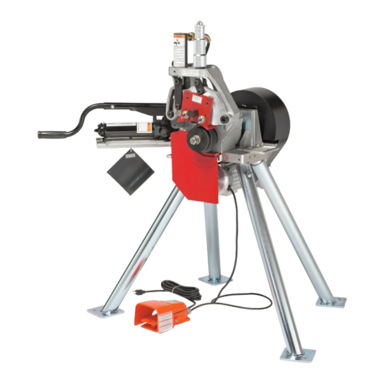
Pipe roll grooving tool
Hide thumbs
Also See for VE270FSD:
- Operating and maintenance instruction manual (195 pages) ,
- Operating and maintenance instruction manual (48 pages)
Table of Contents
Advertisement
Quick Links
TM-VE270FSD.2469 Rev.B Page 1 Sunday, October 28, 2001 4:10 PM
Operating and
R
Maintenance
Instructions
Manual
VE270FSD
Pipe Roll Grooving Tool
Failure to follow Instructions and warnings can result in serious personal injury.
• Before installing, operating or servicing the VE270FSD tool, read this Manual
and all warning labels on the tool.
• Always wear safety glasses and foot protection.
If you need additional copies of the manual or have any questions about the safe
operation of this tool, contact Victaulic Tool Company, P.O. Box 31, Easton, PA
18044-0031, Phone: 610-559-3300.
Advertisement
Table of Contents

Subscribe to Our Youtube Channel
Related Manuals for Victaulic VE270FSD


Summary of Contents for Victaulic VE270FSD
- Page 1 Pipe Roll Grooving Tool Failure to follow Instructions and warnings can result in serious personal injury. • Before installing, operating or servicing the VE270FSD tool, read this Manual and all warning labels on the tool. • Always wear safety glasses and foot protection.
- Page 2 Introduction ......4 Victaulic Adjustable Pipe Stands ..24 Power Requirements .
-
Page 3: Operator Safety Instructions
Prevent accidental startings. Operate with foot switch only. The VE270FSD must be operated with a safety foot switch, located for easy operator access. The switch should always be accessible to the operator. -
Page 4: Power Requirements
Series 270FSD tools are semi-automated hydraulic feed tools for roll grooving of pipe to prepare it to receive Victaulic grooved pipe couplings. The VE270FSD is a completely self- contained unit with a gear motor, safety foot switch and power cord/plug. The VE270FSD is designed to roll groove pipe of various materials and wall thicknesses (see Tool Rating and Roll Selection charts on pages 27 and 28.) -
Page 5: Tool Nomenclature
TM-VE270FSD.2469 Rev.B Page 5 Sunday, October 28, 2001 4:10 PM VE270FSD TOOL NOMENCLATURE Hydraulic Cylinder Pipe Size Indicator Depth Adjuster Depth Adjuster Lock Upper Roll Motor/Drive Guards Hydraulic Pump Stabilizer Assembly Guard Setting Pad Stabilizer Handwheel Lower Roll Foot Switch... -
Page 6: Receiving Tool
TM-VE270FSD.2469 Rev.B Page 6 Sunday, October 28, 2001 4:10 PM VE270FSD RECEIVING TOOL TOOL SETUP VE270FSD tools are palletized individually and covered with a cardboard sleeve designed for use in re-shipping tools. • Do not plug in tool until instructed otherwise. -
Page 7: Pre-Operation Adjustments
TM-VE270FSD.2469 Rev.B Page 7 Sunday, October 28, 2001 4:10 PM VE270FSD GROOVING ROLLS Make sure the proper roll set is on the tool for the pipe size and material to be grooved. They are marked with the pipe size, part number and color coded for the pipe material to be grooved. - Page 8 TM-VE270FSD.2469 Rev.B Page 8 Sunday, October 28, 2001 4:10 PM VE270FSD SHORT PIPE LENGTHS Example: A 20' 4" length of 10" diameter pipe is needed to finish a section and you only have Table 1 shows minimum and maximum pipe 20' lengths available.
-
Page 9: Roll Guard Adjustment
TM-VE270FSD.2469 Rev.B Page 9 Sunday, October 28, 2001 4:10 PM VE270FSD • Pipe stand location will affect pipe tracking. • Incorrect pipe stand position may result in pipe being pushed out of rolls and falling. Failure to position pipe and pipe stand in accordance with Figures 1 and 2 (shown on page 8) may result in serious personal injury or property damage. - Page 10 TM-VE270FSD.2469 Rev.B Page 10 Sunday, October 28, 2001 4:10 PM VE270FSD 6. Close hand pump valve. 4. If so equipped, retract stabilizer, if neces- sary, to insert pipe. To do this, loosen locking handle and retract stabilizer roller with the hand wheel to clear pipe when inserted onto lower roll.
-
Page 11: Pipe Stabilizer Adjustment
TM-VE270FSD.2469 Rev.B Page 11 Sunday, October 28, 2001 4:10 PM VE270FSD 1. Make sure proper roll set is on the tool for the pipe size and material to be grooved. Rolls are marked with pipe size, part number and are color coded for pipe material for your conve- nience. -
Page 12: Groove Diameter Stop Adjustment
TM-VE270FSD.2469 Rev.B Page 12 Sunday, October 28, 2001 4:10 PM VE270FSD 6. Advance stabilizer roller inward with hand- wheel to the position indicated in Figure 3 below, then tighten locking handle. Do not adjust stabilizer to push pipe to the left and off center from the rolls (see Figure 4 at right). - Page 13 TM-VE270FSD.2469 Rev.B Page 13 Sunday, October 28, 2001 4:10 PM VE270FSD 5. Prepare a trial groove. To do so, follow the Grooving Operation Procedures outlined on pages 14 - 16. 3. Back off the depth adjuster lock. Align the depth adjuster with the proper diameter and thickness as shown.
-
Page 14: Grooving Operation
TM-VE270FSD.2469 Rev.B Page 14 Sunday, October 28, 2001 4:10 PM VE270FSD GROOVING OPERATION • Vic-Easy Series VE270FSD tools are designed ONLY for roll grooving pipe of the sizes, materials and wall thicknesses outlined under Tool Rating and Roll Selection charts on pages 27 and 28. - Page 15 TM-VE270FSD.2469 Rev.B Page 15 Sunday, October 28, 2001 4:10 PM VE270FSD 9. Depress and hold down safety foot switch. 5. Close the pressure release valve on the pump by turning clockwise. The pipe will begin to rotate clockwise. As the pipe rotates, begin grooving by slowly pump- ing the pump handle.
-
Page 16: Roll Changing
TM-VE270FSD.2469 Rev.B Page 16 Sunday, October 28, 2001 4:10 PM VE270FSD ROLL REMOVAL PROCEDURE LOWER ROLL – ³⁄₄" & 1 - 1¹⁄₂" SIZES 1. Open hand pump release valve (turn knob counterclockwise) and arm will move to the full open position. - Page 17 TM-VE270FSD.2469 Rev.B Page 17 Sunday, October 28, 2001 4:10 PM VE270FSD 3. With a wrench, loosen large nut on lower shaft and back off approximately ¹⁄₄" without NOTICE removing. Be careful not to lose the Woodruff keys. They should remain in the 2 - 12" arbor. Inspect the Woodruff keys and replace if damaged.
- Page 18 TM-VE270FSD.2469 Rev.B Page 18 Sunday, October 28, 2001 4:10 PM VE270FSD ARBOR SHAFT REMOVAL PROCEDURE See Tool Rating and Roll Selection charts on pages 27 and 28 for information on available • Never operate tool with the jack bolts installed in grooving rolls.
- Page 19 TM-VE270FSD.2469 Rev.B Page 19 Sunday, October 28, 2001 4:10 PM VE270FSD LOWER ROLLS – ³⁄₄" & 1 - 1¹⁄₂" SIZES 3. Carefully slide desired upper roll assembly 1. Clean the bore of the main shaft and the roll onto upper shaft with red plate facing out.
- Page 20 TM-VE270FSD.2469 Rev.B Page 20 Sunday, October 28, 2001 4:10 PM VE270FSD ARBOR SHAFT ROLL INSTALLATION INSTALLATION PROCEDURE PROCEDURE 2" AND LARGER SIZES LOWER ROLL – 2" AND LARGER SIZES NOTICE Arbor shaft must be installed prior to installing 2" and larger size lower rolls.
-
Page 21: Maintenance
TM-VE270FSD.2469 Rev.B Page 21 Sunday, October 28, 2001 4:10 PM VE270FSD MAINTENANCE GENERAL This manual provides information on keeping tools in top operating condition and guidance in making repairs when it becomes necessary. Replacement parts, applicable only to these tools, should be ordered from Victaulic to assure proper operation of the tool. -
Page 22: Hydraulic Systems
TM-VE270FSD.2469 Rev.B Page 22 Sunday, October 28, 2001 4:10 PM VE270FSD HYDRAULIC SYSTEMS The level of hydraulic fluid in the pump must be checked semi-annually or if pumping feels spongy. FILLING AND CHECKING 1. Open pump release valve fully by turning counterclockwise. -
Page 23: Parts Ordering Information
TM-VE270FSD.2469 Rev.B Page 23 Sunday, October 28, 2001 4:10 PM VE270FSD AIR BLEEDING PARTS ORDERING INFORMATION When ordering parts, the following information is necessary for Victaulic to process the order send correct part(s). Request RP-270FSD Parts Manual for detailed drawings and parts listing. -
Page 24: Accessories
TM-VE270FSD.2469 Rev.B Page 24 Sunday, October 28, 2001 4:10 PM VE270FSD ACCESSORIES VICTAULIC ADJUSTABLE STABILIZER ASSEMBLY PIPE STANDS VAPS 112 A pipe stabilizer is available for Series VE270FSD tools. It is designed to prevent pipe sway on 8 - 12" nominal IPS pipe sizes. Contact Victaulic for details. -
Page 25: Troubleshooting
TM-VE270FSD.2469 Rev.B Page 25 Sunday, October 28, 2001 4:10 PM VE270FSD TROUBLESHOOTING Problem Possible Cause Solution Pipe will not stay in Incorrect pipe positioning See “Pipe Support”. grooving rolls. on long pipes. Pipe stops rotating Rust or dirt has built up on Remove accumulation from lower during grooving. - Page 26 TM-VE270FSD.2469 Rev.B Page 26 Sunday, October 28, 2001 4:10 PM VE270FSD TROUBLESHOOTING Problem Possible Cause Solution Pipe flare is excessive. Pipe support adjusted too See “Long Pipe Lengths”. high on long pipes. Tool is tilted forward while See “Tool Setup”.
-
Page 27: Tool Rating And Roll Selection
TM-VE270FSD.2469 Rev.B Page 27 Sunday, October 28, 2001 4:10 PM VE270FSD TOOL RATING AND ROLL SELECTION STANDARD AND “ES” ROLLS – COLOR CODED BLACK 2468-2B PIPE Nominal Dimensions – Inches/ SIZE Nom. Steel Pipe Stain. Steel Pipe Alum. Pipe PVC Plastic Pipe Standard “ES”... -
Page 28: Rolls For Copper Tubing
TM-VE270FSD.2469 Rev.B Page 28 Sunday, October 28, 2001 4:10 PM VE270FSD ROLLS FOR SCHEDULE 5S AND 10S STAINLESS STEEL PIPE (RX ROLLS) – COLOR CODED SILVER 0886-3A Nominal Dimensions – Inches/ Stainless Steel Pipe Wall Thickness † PIPE SIZE Min. -
Page 29: Steel Pipe And All Materials Grooved With Standard And Rx Rolls
TM-VE270FSD.2469 Rev.B Page 29 Sunday, October 28, 2001 4:10 PM VE270FSD ROLL GROOVE SPECIFICATIONS STEEL PIPE AND ALL MATERIALS GROOVED WITH STANDARD AND RX ROLLS Exaggerated for Clarity 0886-5A Dimensions – Inches/ millimeters PIPE Pipe Outside Dia. O.D. Gasket Groove Groove Dia. - Page 30 All loose paint, scale, dirt, chips, grease and rust must be removed. It continues to be Victaulic’s first recommendation that pipe be square cut. When using beveled pipe contact Victaulic for details.
-
Page 31: Drawn Copper Tubing
TM-VE270FSD.2469 Rev.B Page 31 Sunday, October 28, 2001 4:10 PM VE270FSD DRAWN COPPER TUBING 25.06-1A TUBING Pipe O.D. Dimensions – Inches/ millimeters SIZE Inches/ Grv. Width Nom. Gask. Seat Groove Dia. Grv. Depth Min. Allow. Max. Inches +0.03/-0.00 (ref.) Wall Thick. -
Page 32: With "Es" Rolls
TM-VE270FSD.2469 Rev.B Page 32 Sunday, October 28, 2001 4:10 PM VE270FSD STEEL PIPE AND ALL MATERIALS GROOVED WITH “ES” ROLLS Exaggerated for Clarity 0886-6A Dimensions – Inches/ Pipe Outside Dia. O.D. Gasket Seat Groove Width Groove Dia. Nom. PIPE Min. -
Page 33: Dimensions
0.330 0.406 0.375 0.688 323,9 323,9 10,3 17,4 *For reference only. The VE270FSD can not groove all schedules of steel pipe in table. DRAWN COPPER TUBING 0886-8B Nominal Wall Thickness – Inches/ TUBING SIZE Outside Type “M” Type “L” Type “K”... - Page 34 TM-VE270FSD.2469 Rev.B Page 34 Sunday, October 28, 2001 4:10 PM ® Victaulic Factory Representatives and Distributor Stocks Worldwide Victaulic reserves the right to change product specifications, designs and standard equipment without notice and without obligation. ® Registered Trademark of Victaulic ©...
Need help?
Do you have a question about the VE270FSD and is the answer not in the manual?
Questions and answers