
Related Manuals for Grunbeck SODA JET III Premium


Summary of Contents for Grunbeck SODA JET III Premium
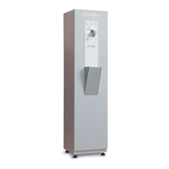
- Page 1 We understand water. Drinking water dispenser | SODA JET III Premium/Public Operation manual...
- Page 2 General Contact Germany International Sales Phone +49 9074 41-145 Technical Service Phone +49 9074 41-333 Fax +49 9074 41-120 Availability Monday to Thursday 7:00 am - 6:00 pm Friday 7:00 am - 4:00 pm We reserve the right to technical modifications. ©...
-
Page 3: Table Of Contents
Other applicable documents ........4 Operating concept ............35 Product identification ..........4 Programs ..............37 Symbols used ............5 Illumination (SODA JET III Premium only)....39 Depiction of warnings ..........6 Emptying the dripping water container .....40 Demands on personnel ..........6 Maintenance and repair ...........47 For your safety ............ -
Page 4: Introduction
Illustrations in this manual are for basic understanding and may differ from the actual design. Validity of the manual This manual applies to the following products: ● Drinking water dispenser SODA JET III Premium ● Drinking water dispenser SODA JET III Public Other applicable documents ●... -
Page 5: Symbols Used
Introduction The type plate is located on the back of the device. Designation Designation Disposal information Power input in standby Obey the operation manual Protection/protection class Product designation Coolant Nominal pressure Empty weight Operating pressure Order no. Nominal flow STILL/MEDIUM/CLASSIC Serial no. -
Page 6: Depiction Of Warnings
Introduction Symbol Meaning Work that must be carried out by technical service personnel only Depiction of warnings This manual contains information and instructions that you must comply with for your personal safety. The information and instructions are highlighted by a warning symbol and are structured as shown below: SIGNAL WORD Type and source of hazard... - Page 7 Introduction 1.6.1 Qualification of personnel Personnel Requirements • No special expertise required Operator/user • Knowledge of the tasks assigned • Knowledge of possible dangers in case of incorrect behaviour. • Knowledge of necessary protective equipment and protective measures • Knowledge of residual risks •...
-
Page 8: For Your Safety
For your safety For your safety Read and obey the instructions below to prevent possible damage. Safety measures ● Only operate your product if all components are installed properly. ● Obey the local regulations on drinking water protection, accident prevention and occupational safety. - Page 9 For your safety 2.1.3 Pressure-related hazards ● Components may be under pressure. Risk of injuries and damage to property due to escaping water and unexpected movement of components. Check the pressure lines for leaks at regular intervals. ● Components of the SODA JET III are under pressure. Do not loosen or remove components which are under operating pressure.
-
Page 10: Product-Specific Safety Instructions
For your safety Product-specific safety instructions 2.2.1 Handling CO cylinders (compressed gas cylinders) The installation of compressed gas cylinders must be carried out by qualified specialists only. The safety instructions and requirements for the operation of compressed gas cylinders must be strictly adhered to (refer to operating instructions order no. 156 959). DANGER Risk of explosion ●... -
Page 11: Conduct In Emergencies
For your safety ● CO pressure reducer with safety valve against overpressure ● Water stop solenoid valve to close the water supply ● Safety valve on the carbonator (11 bar) 2.2.3 Signals and warning signs The affixed information and pictograms must be clearly legible. They must not be removed, soiled or painted over. -
Page 12: Product Description
Product description Intended use ● The drinking water dispensers SODA JET III Premium and SODA JET III Public are used to produce refrigerated and/or carbonated water. ● The drinking water dispensers SODA JET III Premium and SODA JET III Public are designed exclusively for use in the industrial and commercial sector as well as in public facilities. -
Page 13: Product Components
Product description Product components Designation Function Coding with buttons: acknowledgement and program — Electric box as well as LEDs: leak and lack of water Pressure reducer for water Pressure reducer for CO High-pressure pump with pump motor Distributor block with non-return valve and pressure switch for water and CO DS1/DS2 Water stop with disinfection tank and solenoid valve... -
Page 14: Functional Description
Product description Functional description The drinking water dispenser is connected to the cold water network of the domestic drinking water system. In a cooling unit, the incoming drinking water is cooled to the desired temperature. By means of the carbonator, the water of the CLASSIC path is enriched with CO . - Page 15 JET III. Hoses and fastening material are included. 156 391 Time control Thanks to the time control, the illumination of the SODA JET III Premium can conveniently be switched on and off via automatic program. 156 828 Dispenser pipe with touch protection To protect the dispenser pipe from impurities;...
-
Page 16: Transport, Placing And Storage
Transport, placing and storage Transport, placing and storage Dispatch/Delivery/Packaging The device is fixed on a pallet at the factory and secured against tipping. Designation Designation Packaging Label with transport monitoring Packaging straps Pallet ► Obey the instructions on the packaging. ►... -
Page 17: Transport/Placing
Transport, placing and storage Transport/Placing WARNING Risk of tipping over in case of improper transport ● The device can tip over and crush people/limbs. ► Transport the device by means of a forklift or lift truck with appropriate forks only. NOTE: Risk of damage in case of transport in horizontal position ●... -
Page 18: Installation
Installation Installation The installation of the drinking water dispenser represents a major intervention into the drinking water system and must be carried out qualified specialists only. Installation example Designation Designation Electric cable with Schuko plug (1.2 m) Waste water hose (max. height 440 mm) Connection hose DN 8 (flexible stainless steel Drain connection DN 50 acc. - Page 19 Installation ● Keep a minimum distance of 100 mm between the wall and the back of the device. ● The installation site must be adequately illuminated and ventilated. ● A Schuko socket is required within a distance of approx. 1.2 m of the device. •...
-
Page 20: Checking The Scope Of Supply
Installation Checking the scope of supply Designation Designation SODA JET III Premium or SODA JET III Quick manual Public, ready for connection Operating instructions Socket wrench with adhesive holder Seals for dispenser pipe, angle valve, Operation log pressure reducer Operation manual ►... - Page 21 Installation NOTE Dirty drinking water in the feed line ● Impurities, corrosion particles and organic substances in the feed line can damage the device. ► Before connecting the feed line to the device, flush it at maximum flow for several minutes.
- Page 22 Installation NOTE High temperature in the device due to an inadequate air exchange rate ● Functional failure of the cooling unit ● If the operating temperatures reached are too high, the thermal circuit breaker automatically switches off the cooling unit. ►...
- Page 23 Installation 5.4.3 Connecting the device to the water supply Designation Designation Angle valve with 3/8" screw connection Optional waste water hose (to be provided by client) Drain connection DN 50 acc. to DIN EN 1717 Connection hose 1. Feed the connection hose through the opening at the bottom. NOTE Incorrect routing of connection hose ●...
-
Page 24: Electrical Installation
Installation Electrical installation The device features a permanently connected connection cable with Schuko mains plug (1.2 m from the back of the device). ● The socket must not be located below the cold water connection. ● The plug must be fitted in such a way that the device can be unplugged immediately and at all times in the event of malfunctions or maintenance work. -
Page 25: Start-Up/Commissioning
Start-up/Commissioning Start-up/Commissioning The work below must be carried out by qualified specialists only. Recommendation: The initial start-up/commissioning of the product should be carried out by Grünbeck’s technical service personnel. Connecting the compressed gas cylinder (CO cylinder) Obey the operating instructions for handling compressed gas cylinders. Designation Designation outlet (secondary pressure gas line) -
Page 26: Releasing The Water Supply
Start-up/Commissioning Designation Designation Pressure gauge for outlet pressure Shut-off valve Cylinder valve Pressure adjusting screw 5. Open the shut-off valve (turn it to vertical position). 6. Open the cylinder valve of the CO cylinder. » The carbonator fills with CO 7. -
Page 27: Disinfecting The Device
Start-up/Commissioning 1. Open the angle valve of the water supply. 2. Briefly press the MEDIUM button. » Continuous operation starts. Let the water run for approx. 3 minutes. 3. Check the water pressure on the pressure gauge (factory-set to 3.5 bar static). 4. -
Page 28: Checking The Device
Start-up/Commissioning Checking the device 1. Set the Standard operation program (refer to chapter 7.2.1). 2. Check the water and CO carrying lines for leaks (e.g. using leak detection spray). 3. Put the CO cylinder into the housing and secure it at the cylinder holder using the safety chain. - Page 29 Start-up/Commissioning The dispense volume can be corrected subject to the respective primary pressure. The factory setting is made with 3.5 bar primary pressure. If the primary pressure is lower, adjust the dispense volume. Factory settings Component Values pressure switch 3.8 bar pressure reducer 4.5 bar Water pressure switch...
- Page 30 Start-up/Commissioning 3. Proceed as follows to adjust the switching point of the LED for lack of CO pressure switch clockwise – the LED lights a Turn the adjusting screw on the CO b Turn the adjusting screw counter-clockwise – the LED turns off. 4.
- Page 31 Start-up/Commissioning a Turn the adjusting screw counter-clockwise until 0.4 bar is displayed. » The LED for Service starts flashing. 5. Adjust the switching point of the LED for Service as follows: a Turn the adjusting screw on the water pressure switch clockwise – the LED lights up.
- Page 32 Start-up/Commissioning If no water cooling is desired, you can switch off the cooling unit as follows: ► Turn the rotary knob beyond the stop. » You can hear a distinct click. 6.5.4 Setting the dispense volumes The dispense volumes of the tastes CLASSIC and STILL can be set separately on the dispenser unit.
- Page 33 Start-up/Commissioning NOTE Incorrect bypass setting of the high-pressure pump ● An incorrect bypass setting can lead to damage on connecting pipes and components. ► Adhere to the specified values for the bypass setting. The work below must be carried out by Grünbeck's technical service only. In the event that the high-pressure pump was replaced, the bypass setting must be reset.
-
Page 34: Handing Over The Product To The Owner/Operating Company
Start-up/Commissioning Handing over the product to the owner/operating company ► Explain to the owner/operating company how the product works. ► Use the manual to brief the owner/operating company and answer any questions. ► Inform the owner/operating company about the need for inspections and maintenance. -
Page 35: Operation/Handling
Operation/Handling Operation/Handling The device does not have a main switch. The device can only be switched off by disconnecting the power plug from mains. Drinking water is dispensed with three dispense buttons: Symbol Explanation STILL (still water, without carbon dioxide) MEDIUM (slightly sparkling, with low carbon dioxide concentration) CLASSIC (strongly sparkling water, with maximum carbon dioxide concentration) - Page 36 Operation/Handling ► Put the receptacle on the placement area. ► As an alternative, hold the receptacle up to avoid splashing. The drinking water can be tapped using two programs: Standard operation or Continuous operation. Mostly, the program “Standard operation” is used. Standard operation 1.
-
Page 37: Programs
Operation/Handling Programs The programs below can be set for different operating modes: ● Standard operation (to tap water in standard operation) ● Continuous operation (to tap water continuously) ● Disinfection (refer to chapter 8.4.8). ● Setting (for start-up and settings) 7.2.1 Changing programs The program button on the control unit is designed for changing the operating mode. - Page 38 Operation/Handling Button combinations and function Operating Buttons/LEDs Explanation mode Standard Water dispensing by pressing and holding a button. operation ∙ One-minute flushing every 8 hours (only if flushing unit is installed) ∙ All errors are analysed and displayed. ∙ The CO pressure is displayed only (acknowledges itself automatically) ∙...
-
Page 39: Illumination (Soda Jet Iii Premium Only)
Operation/Handling Illumination (SODA JET III Premium only) A fluorescent tube is installed in the inner door. The illumination can be turned on and off by a switch (on the back of the housing). If a time control (optional) is used, the switch is without function. -
Page 40: Emptying The Dripping Water Container
Operation/Handling Emptying the dripping water container ► Proceed as follows to empty the dripping water container in the event of fault signal 1. Pull the mains plug. 2. Unlock the door using the socket wrench. 3. Open the door. Designation Designation Plug of float switch Dripping water container... - Page 41 Operation/Handling 4. Turn and pull the plug of the float switch upwards. 5. Carefully pull the dripping water container from the holder. 6. Drain the dripping water container. 7. Position the dripping water container in the holder. 8. Plug in and screw in the plug of the float switch. 9.
- Page 42 Operation/Handling NOTE Removing the CO cylinder ● The CO pressure reducer can get entangled in the hoses on the inside of the device. ● Hoses and fittings can be damaged. ► Firmly hold on to the CO pressure reducer during the replacement process. ►...
- Page 43 Operation/Handling Checking the content of the cylinder During use, the cylinder pressure is approx. 50 bar. The cylinder pressure only decreases before the CO cylinder is completely empty. The cylinder pressure does not say anything about the remaining residual amount of CO in the cylinder.
- Page 44 Operation/Handling Inserting the full CO cylinder 1. Place the new CO cylinder at the side of the device and secure it with the safety chain of the cylinder holder. 2. Tighten the sealing ring union nut of the pressure reducer again – insert a new seal, if necessary.
- Page 45 Operation/Handling Regulating the CO pressure Designation Designation Lock nut Pressure adjusting screw ► Proceed as follows to regulate the CO pressure, if required: a Loosen the lock nut. pressure – turn the pressure adjusting screw counter- b Reduce the CO clockwise pressure –...
- Page 46 Operation/Handling Restart after changing the cylinder 1. Close the door. 2. Lock the door. 3. Plug in the mains plug. 4. Dispense approx. 1 l of CLASSIC water (with CO ) and discard it. 5. Dispense MEDIUM and CLASSIC water and check a water sample for the criteria below: •...
-
Page 47: Maintenance And Repair
Maintenance and repair Maintenance and repair Maintenance and repair includes cleaning, inspection and servicing of the product. The responsibility for inspection and maintenance is subject to local and national requirements. The owner/operating company is responsible for compliance with the prescribed maintenance and repair work. By concluding a maintenance contract, you make sure that all maintenance work is carried out on time. - Page 48 Maintenance and repair ► Use hygienic gloves while cleaning. ► Only clean the outside of device’s housing. ► Do not use any strong or abrasive cleaning agents. ► Wipe the surfaces with a clean and damp cloth. ► Dry the surfaces with a soft cloth. 8.1.1 Cleaning the operating panel and the drip tray cover plate We recommend cleaning the water dispense area (buttons, dispenser pipe) daily and...
- Page 49 Maintenance and repair 8.1.2 Disinfecting the dispenser pipe We recommend thoroughly disinfecting the dispenser pipe once a week. The intervals are subject to local conditions such as degree of use and user group. WARNING Risk of contaminated drinking water ● Risk of infectious diseases due to bacterial growth at the dispenser pipe. ●...
- Page 50 Maintenance and repair Installing and checking the dispenser pipe 1. Insert the dispenser pipe straight into the opening as far as it will go. 2. Tighten the clamping screw only slightly – turn it clockwise. 3. Close the door and put the device into operation. 4.
-
Page 51: Intervals
• Visually check the connection cable and plug, the connection hose and the housing for damage • Check the (optional) drain connection for free outlet • Check the illumination (SODA JET III Premium) for function • Visually check optional equipment such as cup dispenser and touch protection for damage •... -
Page 52: Inspection
5. Check the connection cable, the connection hose and the housing for damage. 6. Check the (optional) drain connection for damage and free outlet. 7. Check the illumination (SODA JET III Premium) for function. 8. Check the optional features such as cup dispenser and touch protection for firm seat and damage. - Page 53 Maintenance and repair e Visually check the connection hose and replace it in case of damage. Check the (optional) drain connection for damage and free outlet. g Clean the housing on the inside and the outside (refer to chapter 8.1). h Check the (optional) touch protection at the dispenser pipe for a firm seat.
- Page 54 Maintenance and repair 3. Proceed as follows to clean the register of the condenser and the fans: a Use a vacuum cleaner to vacuum off organic material and dust particles or blow them off with compressed air. b Clean the fans with a cleaning brush, if necessary. 4.
- Page 55 Maintenance and repair 8.4.3 Checking sensors and switches Checking the floor sensor Designation Designation Contacts of floor sensor Fault signal: Leak LED and Service LED 1. Check the contacts of the flow sensor for rust formation or other residue. 2. Clean the contacts, if necessary, or replace the floor sensor. 3.
- Page 56 Maintenance and repair 6. Disconnect the device from the power supply – pull the mains plug. 7. Remount the plug of the solenoid valve. 8. Plug in the mains plug and set the Standard operation program. » The solenoid valve of the water stop has worked. Checking the float switch 1.
- Page 57 Maintenance and repair 4. If the Service LED does not light up, readjust the water pressure switch (refer to chapter 6.5.2). Checking the CO pressure switch and the CO pressure reducer Designation Designation pressure switch pressure reducer 1. Close the CO cylinder valve.
- Page 58 Maintenance and repair 8.4.4 Replacing the illumination (SODA JET III Premium only) Designation Designation Bolt latch Starter Inner door of door Fluorescent tube ► Proceed as follows to replace the fluorescent tube: 1. Turn off the illumination and disconnect the device from the power supply.
- Page 59 Maintenance and repair 8.4.5 Changing the (optional) sterile filter The filter insert must be replaced every 6 months. If the water flow is considerably reduced, however, earlier replacement might be required. An earlier replacement is not a defect of the filter used, but an indication of increased occurrence of fine particles and bacteria in the unfiltered water.
- Page 60 Maintenance and repair 1. Loosen the union nut (on the outlet side). 2. Pull the filter insert including collar seal from the empty tube and discard them. 3. Put in a new filter insert with collar seal – mind the flow direction. 4.
- Page 61 Maintenance and repair 2. On the outlet side, insert a flat seal supplied with the device. 3. Only mount the empty tube (included in maintenance kit with order no. 156 858) » The sterile filter is prepared for disinfection. We recommend replacing the filter insert, the empty tube and the flat seal after disinfection has been carried out.
- Page 62 Maintenance and repair 4. Reprogram the water meter in case of deviations. 5. Change the battery (CR 2032), if necessary. 8.4.7 Checking (optional) the flushing unit During disinfection, the function of the flushing unit is checked: phases 2b and 4b. Designation Designation Lines to the dispenser unit...
- Page 63 Maintenance and repair WARNING Health risk due to disinfectant ● Harmful to health when in contact with the skin ● Causes severe skin burns and severe eye damage ► Keep unauthorised persons away. ► Use personal protective equipment (protective gloves and protective goggles). ►...
- Page 64 Maintenance and repair Operating Buttons/LEDs Explanation mode Disinfection The disinfection program is required for maintenance only. Button combinations for the respective disinfection phases • Releasing pressure Phase 1 • All dispense valves open • High-pressure pump is deactivated • Flushing in the disinfectant Phase 2a •...
- Page 65 Maintenance and repair 8.4.8.2 Preparations 1. Remove the CO cylinder from the cylinder holder in the housing. 2. Position the CO cylinder on the right next to the device and secure it with the safety chain (refer to chapter 7.4.1). ►...
- Page 66 Maintenance and repair 8.4.8.3 Phase 1: Adding the disinfectant Designation Designation Disinfection tank Sieve Syringe 1. Tap STILL water for approx. 1 minute. 2. Remove the sterile filter – if installed – and only mount the empty tube with 2 flat seals of the new filter.
- Page 67 Maintenance and repair 8.4.8.4 Phase 2a Flushing in the disinfectant 1. Tap MEDIUM water for approx. 5 seconds. 2. Pull the safety valve (located on the carbonator) upwards. » The CO pressure is relieved. 3. Allow the disinfection tablets to dissolve for at least 1 minute. 4.
- Page 68 Maintenance and repair 8.4.8.5 Phase 2b: Flushing in the disinfectant with the (optional) flushing unit Designation Designation Flushing unit Solenoid valve 1. Press and hold the buttons STILL + MEDIUM for 1 second. » The solenoid valve of the flushing unit opens briefly, and the disinfectant is flushed 8.4.8.6 Phase 3: Allowing the disinfectant to take effect „CO...
- Page 69 Maintenance and repair 8.4.8.7 Phase 4a: Flushing out the disinfectant 1. Press and hold the buttons STILL + CLASSIC until the flushing starts. » The disinfectant is flushed out automatically for 30 seconds. 2. Wait for 1 minute. 3. Repeat these processes 5x (flushing and waiting). 8.4.8.8 Phase 4b: Flushing out the disinfectant with the (optional) flushing unit 1.
- Page 70 Maintenance and repair 8.4.8.9 Completing the disinfection 1. Open the cylinder valve of the CO cylinder. 2. Set the Standard operation program. 3. Tap MEDIUM water until the high-pressure pump briefly starts running. Checking the flushing process ► Use the empty vial (20 ml) for the water analysis. 1.
- Page 71 Maintenance and repair 4. Wipe the test strip and wait for about 30 seconds. 5. Check the test strip for blue colouration. » If the test strip does not show any blue colouration, there is no disinfectant present any longer. »...
- Page 72 Maintenance and repair 8.4.9.1 Checking the CO concentration ► Use the CO tester and the slide rule to determine the CO concentration. The slide rule is required to determine the equilibrium pressure as a function of the CO volume and to calculate the necessary CO delivery pressure.
-
Page 73: Consumables
Sterile filter with seals (as spare part) 156 851e Special fluorescent tube, warm light 156 691e (for SODA JET III Premium) Specification of CO cylinder You can order the CO cylinder from your local SODA JET III sales partner. By concluding a maintenance contract, you make sure that the cylinder is replaced at regular intervals. - Page 74 Maintenance and repair Designation High-pressure pump with or without pump motor Cooling unit: compressor, fan, non-return valves Dispenser unit Designation Water pressure reducer, pressure gauge, non-return valves pressure reducer, pressure gauges, non-return valves Distributor block for with pressure switch for CO and water 8.7.1 Replacement interval of the high-pressure pump...
- Page 75 Maintenance and repair ► The diagram informs you about the replacement intervall of the high-pressure pump. Designation Designation Replacement interval in years Raw water hardness in °dH Designation 1. High-pressure pump ► Have a worn high-pressure pump replaced by Grünbeck’s technical service. ►...
-
Page 76: Malfunctions
Malfunctions Malfunctions WARNING Risk of contaminated drinking water due to stagnation ● Risk of infectious diseases ► Have malfunctions remedied immediately. Signals 1. Eliminate the fault. 2. Acknowledge the fault. 3. Monitor the signals. Status signal Explanation Remedy Dripping water container is full. ►... -
Page 77: Troubleshooting
Malfunctions Troubleshooting 9.2.1 Leak detected. To prevent possible water damage and resulting consequential damage, a floor sensor is integrated on the bottom of the device. The following is triggered when moisture is detected on the bottom of the device: ● The water stop solenoid valve is activated. ●... -
Page 78: Other Observations
Malfunctions Other observations Observation Explanation Remedy ► Set the high-pressure pump When dispensing water, distinct High-pressure pump does not outgassing noises can be heard provide enough power. with the bypass (refer to chapter 6.5.5). (spraying, spluttering) ► Have the high-pressure pump replaced by the technical service (recommended). -
Page 79: Decommissioning
10.1.1 Short operational breaks (through the night) 1. Keep the device connected to the water and power supply. 2. Switch off the illumination on SODA JET III PREMIUM, if no time control is installed. 10.1.2 Operating breaks of up to two days 1. -
Page 80: Restart
Decommissioning 10.2 Restart ► Carry out the tasks below: 1. Open the angle valve of the water supply. 2. Establish the power supply – plug in the mains plug. 3. Open the cylinder valve of the CO cylinder and the shut-off valve of the CO pressure reducer. -
Page 81: Dismantling And Disposal
Dismantling and disposal Dismantling and disposal 11.1 Dismantling ► Have this work done by qualified specialists only. 1. Carry out decommissioning (refer to chapter 10). 2. Disconnect the device from the water installation – remove the connection hose and the drain connection 3. - Page 82 Dismantling and disposal Product If this symbol (crossed-out wheelie bin) is on the product, it means that this product or its electrical and electronic components must not be disposed of as household waste. ► Find out about the local regulations on the separate collection of electrical and electronic products.
-
Page 83: Technical Specifications
Technical specifications Technical specifications Dimensions and weights Premium Public System width System depth C Total system depth D System height 1500 Height of drip tray, approx. Outlet height (clearance), approx. ≥ 100 G Distance to wall Empty weight, approx. Connection data Premium Public Nominal connection diameter... - Page 84 Technical specifications Performance data Premium Public Nominal pressure 2.5 – 10.0 (4.0) Operating pressure (recommended) Power input in standby Power input during dispensing and cooling, W/VA 760/1050 720/980 illumination (if present) Nominal flow Dispense volumes: STILL/MEDIUM/CLASSIC l/min 1.8/2.6/2.1 Carbon dioxide concentration CLASSIC, approx. * Cooling data Premium Public...
-
Page 85: Pid (Flow Chart)
Technical specifications 12.1 PID (flow chart) Designation Designation Water stop Cooling unit Pressure reducer for water Dispenser unit Pressure reducer for CO Dripping water container Distributor block for CO and water (H Coding Designation Disinfection tank Carbonator Pressure reducer for water Pressure reducer for CO Pressure switch for water Pressure switch for CO... -
Page 86: Electrical Connections Of The Control Unit (As Of Serial No. 570441)
Technical specifications Coding Designation RV (H Non-return valve for inlet water Water stop solenoid valve Solenoid valve of dispenser unit for STILL Solenoid valve of dispenser unit for CLASSIC Downstream of the integrated protective function and control, the path of the water separates into two paths: ●... - Page 87 Technical specifications Designation Designation Front of the circuit board Back of the circuit board Coding Function Comment T0.63 A primary, delayed action Fuse for transformers T1 and T2 T4.0 A delayed action Fuse for cooling unit T2.5 A, delayed action Fuse for high-pressure pump T1.6 A secondary, delayed action Fuse for transformer T1 (solenoid valves)
- Page 88 Terminal Signal Colour Comment Mains cable 230 V~ YE-GN Illumination of front foil 230 V~ (SODA JET III Premium), L is switched by the switch on the back of the housing. YE-GN Cooling unit YE-GN Additional PE terminals High-pressure pump 230 V~ YE-GN Fault signal contact (relay) max.
- Page 89 EC/EU guidelines in terms of its design, construction and execution. This certificate becomes void if the system is modified in any way not approved by us. Drinking water dispenser SODA JET III Premium/Public Serial no.: Refer to type plate Furthermore, we confirm compliance with the essential requirements of the EMC Directive 2014/30/EU.
- Page 91 Impressum Technische Dokumentation Bei Fragen und Anregungen zu dieser Betriebsanleitung wenden Sie sich bitte direkt an die Abteilung Technische Dokumentation bei Grünbeck Wasseraufbereitung GmbH email: dokumentation@gruenbeck.de...
- Page 92 Grünbeck Wasseraufbereitung GmbH Josef-Grünbeck-Str. 1 89420 Hoechstaedt/Germany +49 9074 41-0 +49 9074 41-100 info@gruenbeck.com For more information go to www.gruenbeck.com www.gruenbeck.com...
Need help?
Do you have a question about the SODA JET III Premium and is the answer not in the manual?
Questions and answers