Table of Contents
Advertisement
Quick Links
Advertisement
Table of Contents

Related Manuals for Grunbeck SODA JET Office


Summary of Contents for Grunbeck SODA JET Office
- Page 1 We understand water. Drinking water dispenser | SODA JET Office Operation manual...
- Page 2 Central Contact Germany Sales +49 (0)9074 41-0 Service +49 (0)9074 41-333 service@gruenbeck.de Availability Monday to Thursday 7:00 am - 6:00 pm Friday 7:00 am - 4:00 pm We reserve the right to technical modifications. © by Grünbeck Wasseraufbereitung GmbH Original operation manual Edition: July 2023 Order no.: 100182220000_en_074...
-
Page 3: Table Of Contents
Table of contents Table of contents Checking the device ..........36 Table of contents ..............3 Handing over the product to the owner/operating company ..............38 Introduction ............... 4 Validity of the manual ..........4 Operation/handling ..........39 Other applicable documents ........4 Product identification .......... -
Page 4: Introduction
Validity of the manual This manual applies to following products: ● Drinking water dispenser SODA JET Office Standard ● Drinking water dispenser SODA JET Office with flushing unit ● Special versions which essentially correspond to the indicated standard products. Other applicable documents ●... -
Page 5: Symbols Used
Introduction Designation Designation Warning symbol for flammable substances Rated voltage/frequency Power input (current consumption) during Disposal information dispensing and cooling Obey the operation manual Coolant and climatic category CE mark Empty weight Nominal pressure Data matrix code Operating pressure Product designation Nominal flow STILL/MEDIUM/CLASSIC QR code Ambient temperature... -
Page 6: Depiction Of Warnings
Introduction Depiction of warnings This manual contains information which you must observe for your own personal safety. This information is highlighted by a warning sign and has the following structure: SIGNAL WORD Type and source of the hazard ● Possible consequences ►... - Page 7 Introduction 1.6.2 Authorisations of personnel The following table describes which activities are allowed to be performed by whom. Operator/ Owner/ Qualified Technical user operating specialist service company Transport and storage Installation and mounting Start-up Operation and handling Cleaning Inspection Maintenance Troubleshooting Repair Shutdown and restart...
-
Page 8: Safety
Safety Safety Safety measures ● Only operate your product if all components are installed properly. ● Obey the local regulations on drinking water protection, accident prevention and occupational safety. ● Do not make any changes, alterations, extensions or program changes on your product. -
Page 9: Product-Specific Safety Instructions
Safety 2.1.4 Electrical dangers There is an immediate danger of fatal injury from electric shock when touching live components. Damage to the insulation or individual components can be life-threatening. ● Only have qualified electricians carry out electrical work on the device. ●... - Page 10 Safety ● The mains cable of the device must be laid free of kinks and tension. ● Do not wind up or squeeze the mains cable of the device. ● A damaged mains cable on the device must be replaced by the manufacturer, or their after-sales service, or a similarly skilled person in order to avoid hazards.
- Page 11 Safety 2.2.5 Handling CO cylinders (compressed gas cylinders) The installation of compressed gas cylinders must be carried out by qualified specialists only. The safety instructions and requirements for the operation of compressed gas cylinders must be strictly adhered to. DANGER Risk of explosion ●...
-
Page 12: Conduct In An Emergency
Safety 2.2.6 Safety devices ● Pressure reducer for water incl. non-return valve ● Safety valve on the carbonator (7.5 bar) ● CO pressure reducer with safety valve against overpressure in the case of an external CO cylinder 2.2.7 Signals and warning devices The affixed information and pictograms must be clearly legible. -
Page 13: Product Description
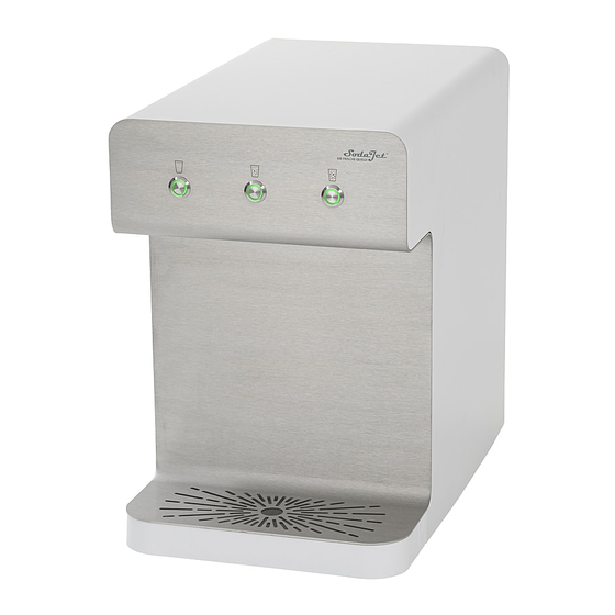
● The SODA JET Office drinking water dispenser is designed for the generation of refrigerated and/or carbonated water. ● The SODA JET Office drinking water dispenser is designed for use in the industrial and commercial sector, as well as in public facilities. -
Page 14: Product Components
Product description Product components Designation Functions/characteristics Dispense buttons with LED for the 3 tastes and status signals Placement area for collection container with drip tray cover plate Dripping water pan extendable, with level and contact sensor Adjustable feet made of rubber for vibration damping Drain connection with hose adaptor for dripping water pan and outlet hose to the drain Griprail... -
Page 15: Functional Description
If the dripping water pan is full, or not in the device, a fault signal is given by the MEDIUM LED flashing. SODA JET Office with flushing unit (optional) This flushes the content of the device to the drain at regular intervals. Stagnation times are reduced, and hygiene is improved. -
Page 16: Accessories
Grünbeck’s headquarters in Hoechstaedt/Germany for details. Illustration Product Order no. SODA JET Office base cabinet 156710000000 to hold the SODA JET Office drinking water dispenser and accommodate the CO cylinder set large 156711000000 for 6 kg and 10 kg CO cylinders, incl. -
Page 17: Transport, Installation And Storage
Transport, installation and storage Transport, installation and storage Shipping/Delivery/Packaging The device is fixed on a pallet at the factory and secured against tipping. ► Obey the instructions on the packaging. ► Load and unload the device with a forklift or lift truck with appropriate forks. Transport/Placing WARNING Tipping over in case of inappropriate transport... -
Page 18: Storage
With fixed connection of the dripping water pan with outlet hose to the drain, e.g. for SODA JET Office with flushing unit. ► Attach the outlet hose to the pre-mounted hose adaptor on the device (refer to chapter 5.4.4). -
Page 19: Installation
Installation Installation The installation of the device represents a major intervention in the drinking water system and must be carried out by a qualified specialist only. Installation example on kitchen top Designation Designation Transparent hose (approx. 1.8 m) for external Mains cable with Schuko mains plug (1.5 m) cylinder with CO pressure reducer... - Page 20 Installation example on the base cabinet (optional) Designation Designation Outlet hose from the dripping water pan Drinking water dispenser SODA JET Office (approx. 1.5 m) and flushing wastewater hose angle valve on site from flushing unit (optional) Connection hose DN 8 (flexible stainless steel...
-
Page 21: Requirements For The Installation Site
Installation Requirements for the installation site The drinking water dispenser may not be operated outdoors. ● The drinking water dispenser must not be placed directly at a water withdrawal point (e.g. directly next to a water tap) where splash water is to be expected. ●... -
Page 22: Checking The Scope Of Supply
Designation SODA JET Office Standard or Drain connection DN 50 acc. to DIN EN 1717 with fastening material SODA JET Office with flushing unit (optional) connection hose for drinking water with 3/8” Operation log screw connection and seals Operation manual... -
Page 23: Water Installation
Installation Water installation 5.4.1 Preliminary work ● If the device was transported lying down, it must be stored upright for at least 24 h (refer to chapter 4.2). ► After unpacking, allow the unit to acclimatise at the installation site for at least 1 hour. - Page 24 Installation 5.4.2 Setting up and connecting the device Designation Designation Schuko socket in the range of 1.2 m Water connection (angle valve 3/8") Feed-through hole for: Drain connection DN 50 acc. to DIN EN 1717 Connection line, drinking water, CO line, outlet hose from the dripping water pan, flushing wastewater hose (optional)
- Page 25 Installation NOTE High temperature in the device due to an inadequate air exchange rate ● Functional failure of the cooling unit ● The thermal circuit breaker switches off the cooling unit automatically if the operating temperatures are reached. ► Keep the ventilation openings on the back of the device clear. »...
- Page 26 Installation 5.4.3 Connecting the device to the water supply 1. Unscrew the water connection cap. a Keep the cap in a safe place. 2. Check whether the cap sieve is inserted. Designation Designation Connection hose DN 8 with 3/8” screw Water connection on the device (3/8”...
- Page 27 The dripping water is discharged directly to the drain. The dripping water pan does not need to be emptied. The installation of the drain connection is mandatory for SODA JET Office with flushing unit. The flushing water is fed into the drain when the device is flushed.
- Page 28 Installation 3. Insert the dripping water pan centrally under the drip tray cover plate. 4. Insert the dripping water pan until it clicks into place. » The outlet hose is connected to the dripping water pan. 5.4.4.2 Connecting the dripping water pan to the drain connection The outlet hose must be laid free of kinks and tension and with a downward slope to the drain.
- Page 29 5. Align the drain connection vertically and insert the outlet hose firmly into the fixing clamp. 5.4.5 Connect SODA JET Office to the flushing wastewater hose The installation of the drain connection is mandatory for SODA JET Office with flushing unit. 5.4.5.1 Fixing the drain connection 1.
- Page 30 Installation Designation Designation Flushing wastewater hose Connecting piece to the drain connection Connection for flushing unit 3. Connect the flushing wastewater hose to the connecting piece of the connection for the flushing unit. 4. Put the flushing wastewater hose on the smallest connecting piece (Ø 8) of the drain connection.
-
Page 31: Electrical Installation
Installation Electrical installation The device features a permanently connected mains cable with Schuko mains plug (1.5 m from the back of the device). ● Portable multiple sockets or power supply units must not be placed at the back of the device. ●... -
Page 32: Connecting The Compressed Gas Cylinder (Co Cylinder)
Installation Connecting the compressed gas cylinder (CO cylinder) The connection and installation of a compressed gas container may only be carried out by a qualified specialist. Observe the operating instructions for handling compressed gas containers (refer to chapter 2.2.1). WARNING Escaping CO gas due to the incorrect routing of the CO line... - Page 33 Installation 1. Place the CO cylinder in a stable position in the installation room and secure it using the safety chain or a safety belt. a Remove the protective cap, if present. 2. Screw the union nut (with inserted sealing ring) of the CO pressure reducer to the connection of the CO cylinder.
- Page 34 Installation line – briefly pull on the CO 2. Check the tight fit of the CO line. » The connection ring blocks the CO line against being pulled out. 3. Loosen the plug-in connection as follows: Press and hold the ring while pulling on the CO line at the same time.
-
Page 35: Start-Up
Start-up Start-up The work below must be carried out by qualified specialists only. Recommendation: The initial start-up of the product should be carried out by the technical service personnel. Releasing the water supply The water inlet pressure must not exceed 6 bar. Recommended 4.0 bar. If the inlet water pressure of at least 2.5 bar is not adequately available or not constant, a fault message can occur. -
Page 36: Disinfecting And Flushing The Device
Start-up Disinfecting and flushing the device At the end of start-up, we recommend disinfecting the device. ► Carry out disinfection (refer to chapter 8.5). ► Carry out flushing (refer to chapter 7.3). Checking the device 1. Check the device and the lines carrying water and CO for leaks. - Page 37 Start-up 6.3.1 Setting the cooling temperature The lower the set water temperature, the higher the carbon dioxide content and the energy consumption of the device. ● By setting the cooling temperature higher, the device's energy consumption can be reduced. Designation Rotary knob on the thermostat ►...
-
Page 38: Handing Over The Product To The Owner/Operating Company
Start-up Handing over the product to the owner/operating company ► Explain to the owner/operating company how the product works. ► Use the manual to brief the owner/operating company and answer any questions. ► Inform the owner/operating company about the need for inspections and maintenance. -
Page 39: Operation/Handling
Operation/handling Operation/handling The device does not have a main switch. The device can only be switched off by disconnecting the power plug from mains. Drinking water is dispensed using three dispense buttons. Symbol Explanation STILL (still water, without carbon dioxide) MEDIUM (slightly sparkling, with low carbon dioxide concentration) CLASSIC (strongly sparkling water, with maximum carbon dioxide concentration) - Page 40 Operation/handling At full cooling capacity for CLASSIC and MEDIUM, observe the tapping time (max. 5 minutes) and operational break time (min. 10 minutes). This corresponds to a dispensing capacity of 30 l/h for CLASSIC and MEDIUM water. For STILL water continuous tapping at full cooling capacity is possible for up to 90 l/h. After longer downtimes, splashing may occur at the start of tapping.
-
Page 41: Emptying The Dripping Water Pan
Operation/handling Operating mode Dispense buttons/LEDs Explanation • The dispense button LED lights up MEDIUM water dispensing • The dispense button LED lights up CLASSIC water dispensing • The dispense button LED lights up Flushing for optional flushing unit • Flushing during disinfection or after prolonged standstill ►... -
Page 42: Perform Flushing
Operation/handling 3. Empty the dripping water pan. 4. Clean and dry the dripping water pan. Ensure that the contacts are not damaged. The dripping water pan can be cleaned in the dishwasher. 5. Insert the dripping water pan centrally under the drip tray cover plate. 6. - Page 43 Operation/handling 1. Press the STILL and CLASSIC dispense buttons at the same time for longer than 3 seconds. » The flushing process starts. 2. Hold the dispense buttons approx. 20 - 25 seconds. » The flushing water is drained into the drain via the flushing unit. 3.
-
Page 44: Changing The Compressed Gas Cylinder (Co Cylinder)
Operation/handling » The flushing water is collected in the collection container. 4. Interrupt the flushing process and empty the collection container if necessary. 5. Release the dispense button to finish the flushing process. ► Carry out a functional check and take a water sample. Changing the compressed gas cylinder (CO cylinder) In the event of fault signal 3 water can continue to be withdrawn. - Page 45 Operation/handling 7.4.1 Removing the empty CO cylinder 1. Disconnect the device from the power supply - remove the mains plug. 2. Close the cylinder valve of the CO cylinder. 3. Close the shut-off valve of the CO pressure reducer. a Operate the pressure relief valve on the pressure controller, if there is one. 4.
- Page 46 Operation/handling 7.4.2 Inserting the full CO cylinder 1. Prepare the new CO cylinder and remove the protective cap. 2. Secure the CO cylinder against falling over with a safety chain or safety belt. 3. Tighten the sealing ring union nut of the pressure reducer again – insert a new seal, if necessary.
- Page 47 Operation/handling 7.4.3 Restart after changing the cylinder 1. Plug in the mains plug. 2. Dispense approx. 1 l of CLASSIC water (with CO ) and discard it. 3. Dispense MEDIUM and CLASSIC water and check a water sample for the criteria below: •...
-
Page 48: Maintenance And Repair
Maintenance and repair Maintenance and repair Maintenance and repair includes cleaning, inspection and maintenance of the product. The responsibility for inspection and maintenance is subject to local and national requirements. The owner/operating company is responsible for compliance with the prescribed maintenance work. By concluding a maintenance contract, you make sure that all maintenance work is done on time. - Page 49 Maintenance and repair ► Use hygienic gloves while cleaning. ► Only clean the outside of the device’s housing. ► Do not use any strong or abrasive cleaning agents. ► Wipe the surfaces with a clean and damp cloth. ► Dry the surfaces with a soft cloth. 8.1.1 Clean the operating panel, drip tray cover plate with dripping water pan Use hygienic gloves for cleaning work to avoid germs during cleaning.
-
Page 50: Intervals
Maintenance and repair Intervals By way of regular inspections and maintenance, malfunctions can be detected in time and device failure might be avoided. ► (As owner/operating company) Determine which components have to be inspected and maintained at which intervals (load-dependent). These intervals are subject to the actual conditions, e.g.: water condition, degree of impurities, environmental influences, consumption, etc. -
Page 51: Inspection
Maintenance and repair Inspection You, as owner/operating company, may perform the regular inspections yourself. Initially, we recommend inspecting the device at shorter intervals and later on as required. ► Carry out an inspection at least once a month and proceed as follows when doing 1. - Page 52 Maintenance and repair 6. Check the drain connection for damage and free outlet. 7. Clean the outside of the housing (refer to chapter 8.1). 8.4.2 Clean the ventilation slats and check the cooling function A dirty cooling unit results in higher power consumption (switch-off point is not reached any longer), poor efficiency and frequent system failures (overheating).
-
Page 53: Disinfect
Maintenance and repair 8.4.3 Check the CO cylinder During use, the cylinder pressure is approx. 50 bar. The cylinder pressure only decreases before the CO cylinder is completely empty. The cylinder pressure does not reveal anything about the residual amount of CO in the cylinder. - Page 54 Maintenance and repair Before disinfection is carried out, attention must be drawn to the maintenance work on the device. ► Place enclosed warning label clearly visible on the SODA JET Office. WARNING Health risk due to disinfectant ● Harmful to health when in contact with the skin ●...
- Page 55 Maintenance and repair 5. Disconnect the device from the power supply. 6. Close the cylinder valve of the CO cylinder. 8.5.2 Preparing the disinfection tank Small amounts of water may leak from the disinfection tank. ► Keep a cloth ready to absorb any leaking water. ►...
- Page 56 Maintenance and repair CAUTION Narrow, sharp-edged operating point on the closing cap ● Crushing/cutting of fingers ► Use protective gloves. ► Use pliers if the closing cap is stuck. 2. Drain the disinfection tank using the syringe. 3. Place 1 disinfection tablet in the disinfection tank. 4.
- Page 57 Maintenance and repair 8.5.3 Flush in disinfectant and allow it to take effect 1. Press the MEDIUM dispense button until the water flows. 2. Wait until the disinfection tablet has dissolved (≥ 5 minutes). 3. Press the CLASSIC dispense button until the water turns slightly yellow. 4.
- Page 58 Maintenance and repair 4. Press and keep the CLASSIC dispense button pressed until approx. 1 litre of water has been dispensed. 5. Press and keep the STILL dispense button pressed until approx. 1 litre of water has been dispensed. 6. Interrupt the flushing process and empty the collection container if necessary. 7.
- Page 59 Maintenance and repair 8.5.6 Completing the disinfection 1. Check the setting of the temperature controller. 2. Press the MEDIUM dispense button until the pump briefly starts running for the first time. 3. Check all connections (CO path and water path) for leaks. 4.
-
Page 60: Consumables
Maintenance and repair Consumables Product Quantity Order no. SODA JET Office disinfection kit for 2 applications 156000010000 Hydrogen peroxide spray 1 piece 156 868 Herlisil S6, for spray disinfection of the dispenser pipe Specification of CO compressed gas cylinder You can order the CO cylinder from your local SODA JET sales partner. -
Page 61: Fault
Fault Fault WARNING Contaminated drinking water due to stagnation ● Infectious diseases due to bacterial growth ► Have malfunctions remedied immediately. If a fault cannot be rectified, the technical service or a qualified specialist trained by Grünbeck can take further measures. ►... -
Page 62: Other Observations
Fault Other observations Observation Explanation Remedy ► Establish power supply - plug When tapping no drinking water Device is de-energised comes out in the mains plug ► Check the mains cable and mains plug for damage ► Contact technical service in the event of damage ►... -
Page 63: Shutdown
Shutdown Shutdown 10.1 Temporary shutdown Carbonators must be used at regular intervals. Stagnating water can cause germs, especially in unrefrigerated areas, and retroactively worsen the hygiene standard of the device. 10.1.1 Short operational breaks (through the night) 1. Keep the device connected to the water and power supply. 10.1.2 Operational breaks of up to three days 1. -
Page 64: Restart
Shutdown 10.2 Restart 1. Open the angle valve of the water supply. 2. Establish the power supply. 3. Open the cylinder valve of the CO cylinder and the shut-off valve of the CO pressure reducer. 4. Carry out start-up/commissioning (refer to chapter 5.6). a Disinfect the device (refer to chapter 8.5). -
Page 65: Dismantling And Disposal
Dismantling and disposal Dismantling and disposal 11.1 Dismantling ► Have this work carried out by qualified specialists only. 1. Carry out shutdown (refer to chapter 10). 2. Disconnect the device from the water installation – remove the connection hose and the drain connection 3. - Page 66 Dismantling and disposal Product If this symbol (crossed-out wheelie bin) is on the product, this product or its electrical and electronic components must not be disposed of as household waste. ► Find out about local regulations on the separate collection of electrical and electronic products.
-
Page 67: Technical Specifications
Technical specifications Technical specifications Dimensions and weights System width System depth System height Outlet height (clearance) ~ 280 Height of dripping water pan Total system depth ≥ 50 Distance to wall Empty weight ~ 32.5 Connection data Nominal connection diameter DN 8 Connection hose (flexible stainless steel braided hose) 1500... - Page 68 Technical specifications Performance data Nominal pressure PN 6 2.5 – 7.1 (4.0) Operating pressure (recommended) Electrical power input idle mode ≤ 370 Power input during dispensing operation and cooling ≤ 2 Power input during dispensing and cooling Nominal flow Dispense volumes: STILL/MEDIUM/CLASSIC l/min 1.5/2.0/1.5 Carbon dioxide concentration CLASSIC, approx.
- Page 69 EU guidelines in terms of its design, construction and execution. This certificate will become invalid if the system is modified in a way not approved by us. Drinking water dispenser SODA JET Office Serial no.: refer to type plate The aforementioned system complies with the following directives and provisions: •...
- Page 70 The tests are performed in accordance with Regulation (EU) No. 10/2011 in conjunction with Annex V. The materials and raw materials used comply with Regulation (EU) No. 10/2011. The SODA JET Office drinking water dispenser is designed for the generation of refrigerated and/or carbonated water.
- Page 71 Publisher's information Technical documentation If you have any questions or suggestions regarding this operation manual, please contact the Technical Documentation Department at Grünbeck Wasseraufbereitung GmbH Email: dokumentation@gruenbeck.de...
- Page 72 Grünbeck Wasseraufbereitung GmbH Josef-Grünbeck-Str. 1 89420 Hoechstaedt; Germany +49 (0)9074 41-0 +49 9074 41-100 info@gruenbeck.com For more information go to www.gruenbeck.com www.gruenbeck.com...
Need help?
Do you have a question about the SODA JET Office and is the answer not in the manual?
Questions and answers