Table of Contents
Advertisement
Quick Links
Advertisement
Table of Contents

Related Manuals for Grunbeck GENO-mat duo WE-X 65


Summary of Contents for Grunbeck GENO-mat duo WE-X 65
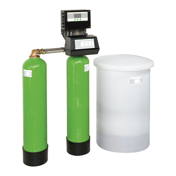
- Page 1 We understand water. Water softener | GENO-mat duo WE-X/WEW-X Operation manual...
- Page 2 General Contact Germany International Sales +49 9074 41-145 Service +49 9074 41-333 service@gruenbeck.de Availability Monday to Thursday 7:00 am - 6:00 pm Friday 7:00 am - 4:00 pm We reserve the right to technical modifications. © by Grünbeck Wasseraufbereitung GmbH Original operation manual Edition: November 2022 Order no.: 100198980000_en_164...
-
Page 3: Table Of Contents
Table of contents Table of contents Handing over the product to the owner/operator/ Introduction ............... 4 operating company ...........46 Validity of the manual ..........4 Other applicable documents ........4 Operation ..............47 Product identification ..........4 Operating concept ............47 Symbols used ............5 Refilling salt tablets ...........55 Depiction of warnings .......... -
Page 4: Introduction
Validity of the manual This manual applies to the products below: ● Water softener GENO-mat duo WE-X 65 – 750 (full salting) ● Water softener GENO-mat duo WE-X 50 – 530 (economy salting) ● Water softener GENO-mat duo WEW-X 65/150 (warm water) This manual applies to the control unit IONO-matic WE as of software V2.34. -
Page 5: Symbols Used
Introduction Designation Designation CE mark Protection/protection class EAC test mark Operating voltage Obey the operation manual Rated voltage range/frequency Disposal information Ambient temperature Product designation Water temperature Operating weight Nominal capacity Date of manufacture value Data matrix code Continuous flow Order no. -
Page 6: Depiction Of Warnings
Introduction Depiction of warnings This manual contains information and instructions that you must obey for your personal safety. The information and instructions are highlighted by a warning symbol and are structured as shown below: 1.5.1.2 SIGNAL WORD 1.5.1.3 Type and source of hazard 1.5.1.1 ●... - Page 7 Introduction 1.6.2 Authorisations of personnel The table below describes which tasks may be carried out by whom. User Owner/ Qualified Technical operator/ specialist service operating company Transport and storage Installation and mounting Start-up/commissioning Operation and handling Cleaning Inspection Maintenance semi-annually annually Troubleshooting Repair...
-
Page 8: Safety
Safety Safety Safety measures ● Only operate your product if all components are installed properly. ● Obey the local regulations on drinking water protection, accident prevention and occupational safety. ● Do not make any changes, alterations, extensions or program changes on your product. -
Page 9: Product-Specific Safety Instructions
Safety ● Never bridge electrical fuses. Do not disable fuses. Use the correct current ratings when replacing fuses. ● Keep moisture away from live parts. Moisture can cause short-circuits. 2.1.4 Groups of persons requiring protection ● This product must not be used by persons (including children) with limited abilities, lack of experience or knowledge. -
Page 10: Conduct In Emergencies
Safety ► Obey all warnings and safety instructions. ► Immediately replace illegible or damaged symbols and pictograms. 2.2.2 Safety-related components Safety components must be replaced by genuine spare parts only. ● Control valve and control unit ● Brine valve ● Water meter ●... -
Page 11: Product Description
Product description Product description Intended use 3.1.1 Water softeners GENO-mat duo WE-X The water softeners GENO-mat duo WE-X are designed for the continuous production of softened and partially softened water and can be used in these areas: ● Continuous soft water supply ●... -
Page 12: Product Components
Product description 3.1.3 Application limits Observe the country-specific stipulations for soft water hardness in the drinking water sector. ● The water to be softened must be free of iron and manganese. • Iron < 0.2 mg/l • Manganese < 0.05 mg/l 3.1.4 Foreseeable misuse ●... -
Page 13: Connections
Product description Connections Designation Designation Connection of brine hose Soft water outlet Connection of hose to drain Raw water inlet Functional description 3.4.1 Process The water softeners GENO-mat duo WE-X/WEW-X work according to the ion exchange principle. The exchange of calcium and magnesium ions for sodium ions causes the water to become soft. -
Page 14: Application In The Drinking Water Sector
Product description Application in the drinking water sector Country-specific requirements ● Czech Republic: According to the czech decree no. 252/2004 softened drinking water should not fall below a soft water hardness of 2 mmol/l (approx. 11°dH) ● Austria: In Austria, softened drinking water must have a soft water hardness of at least 8.4 °dH. - Page 15 Product description 3.6.3 Disinfection unit (optional for systems with economy salting) WARNING Contaminated drinking water due to stagnation ● Infectious diseases due to bacterial growth ► Make sure that there is a continuous flow and avoid prolonged periods of standstill. ►...
-
Page 16: Accessories
Product description Accessories You can retrofit your product with accessories. Please contact your local Grünbeck representative or Grünbeck’s headquarters in Hoechstaedt/Germany for details. Illustration Product Order no. Connection kit 1" 185 515 1¼" 185 530 1½" 185 545 1"-I 185 505 Industrial version 1¼"-I 185 520... - Page 17 Product description Illustration Product Order no. 125 809 Blending valve 1" with DVGW blending Adapter connection with integrated blending unit R 1" • Included in the scope of supply of duo WE-X 50/130/230 with economy salting • Available as an option for duo WE-X 65/150/300 with full salting. Disinfection unit duo WE-X 50 –...
-
Page 18: Transport, Set-Up And Storage
Transport, set-up and storage Transport, set-up and storage Shipping/Delivery/Packaging The system parts/packages are fixed on a pallet at the factory and secured against tipping. ► Upon receipt, immediately check for completeness and transport damage. NOTE Improper transport ● Damage to system parts due to components falling down. ●... -
Page 19: Storage
Transport, set-up and storage Storage ► Protect the product from the impacts below when storing it: • Dampness, moisture • Environmental impacts such as wind, rain, snow, etc. • Frost, direct sunlight, severe heat exposure • Chemicals, dyes, solvents and their vapours 4.3.1 Regenerant ►... -
Page 20: Installation
Installation Installation The installation of the system represents a major intervention into the drinking water system and must be carried out by a qualified specialist only. WARNING Contaminated drinking water due to stagnation ● Infection due to bacterial growth ► Do not connect the system to the drinking water system until immediately before start-up/commissioning. - Page 21 Installation Installation example II (GENO-mat duo WE-X in DN 40 version) Designation Designation Safety device protectliQ Connection kit 1½" Drinking water filter BOXER Water withdrawal point Euro system separator GENO-DK 2 Drain connection DN 50 acc. to DIN EN 1717 Installation example III (GENO-mat duo WEW-X) Designation Designation...
-
Page 22: Requirements For The Installation Site
Installation Requirements for the installation site Obey the local installation directives, general guidelines and technical specifications. ● Protection from frost, severe heat exposure and direct sunlight ● Protection from chemicals, dyes, solvents and their vapours ● Ambient temperature and radiation temperature in the immediate vicinity of the GENO-mat duo WE-X •... -
Page 23: Checking The Scope Of Supply
Installation Electrical installation ● Schuko socket with continuous power supply (max. about 1.2 m from the control unit) Checking the scope of supply 5.3.1 GENO-mat duo WE-X/WEW-X in DN 25 version The exchangers are filled with ion exchange resin at the factory. Designation Designation Salt dissolving tank with brine valve and... - Page 24 Installation 5.3.2 GENO-mat duo WE-X in DN 40 version Designation Designation Water test kit “Total hardness” Bottle adapter Connecting pipes with control unit and screw Ion exchange resin connection Filling funnel Control valve Operation manual Water meter Brine hose for brine valve including connecting Salt dissolving tank with brine valve and accessories overflow hose...
-
Page 25: Water Installation
Installation Water installation The system only functions if it is set up correctly. ► Always place the exchanger tank with control valve on the right-hand side (seen from the front). CAUTION Exchanger tanks can tip and fall over ● Pushing/crushing people ►... - Page 26 Designation Connection block Blending valve 1" In case of GENO-mat duo WE-X 65/150/300 with full salting, the standard connection block is to be installed. In case of GENO-mat duo WE-X 50/130/230 with economy salting, the connection block with blending valve is to be installed.
- Page 27 Installation 5.4.1.1 Connecting the water lines and installing the water meter ► Thoroughly flush the water supply line to flush out dirt and corrosion particles from the supply line. Installing the water meter 1. Prepare the soft water line for the installation of the water meter. 2.
- Page 28 Installation Installation with connection kit 1. Install the screw connection into the pipe. 2. Install the connection block of the connection kit – comply with the flow direction. 3. Install the water meter on the connection of the soft water outlet. NOTE Incorrect installation of connection hoses ●...
- Page 29 Installation Designation Designation Raw water line Soft water sample Connection kit Water meter 5.4.2 GENO-mat duo WE-X in DN 40 version 5.4.2.1 Filling the exchanger tanks The exchangers tanks must be filled with exchange resin by the client on site. System WE-X 330 and WE-X 450 WE-X 530 and WE-X 750...
- Page 30 Installation 1. Check that the riser pipe is closed by the cap. The cap prevents the exchange resin from entering the riser pipe. The riser pipe must be centred, so that the bottle adapter and the control valve can be installed.
- Page 31 Installation 5. Push the head nozzle of the bottle adapter from above over the riser pipe of the exchanger tank on the left. 6. Fix the bottle adapter on the exchanger tank by turning it clockwise. Obey the attached mounting instructions for the installation of the connecting pipes. 7.
-
Page 32: Setting Up And Connecting The Salt Dissolving Tank
Installation Setting up and connecting the salt dissolving tank Designation Designation Flushing water pipe Overflow hose Brine hose 1. Place the salt dissolving tank in the immediate vicinity of the water softener. a Take the length of the hoses of the salt dissolving tank and of the water softener into account. - Page 33 Installation 5.5.1.1 Connecting the brine hose Fastening the brine hose on the brine valve Designation Designation Elbow union Brine hose Transition nipple Crimp ring Lid of brine valve Support sleeve Brine valve Filter 1. Remove the lid of the salt dissolving tank. You can remove the brine valve to make installing the brine hose easier.
- Page 34 Installation Fastening the brine hose on the injector 8. Fasten the brine hose on the injector with crimp ring, inserted support sleeve and union nut on the injector. Fastening the brine hose on the (optional) disinfection unit 9. Insert the brine hose into the plug-in connection as far as it will go. 10.
- Page 35 Installation 5.5.1.2 Establishing the waste water connection NOTE Build-up of waste water in the flushing water hose ● Damage to the system and malfunction ► Make sure not to bend the flushing water hose or not to route it higher than the system height.
-
Page 36: Electrical Installation
Installation Electrical installation The electrical installation must be carried out by a qualified electrician only. DANGER Life-threatening voltage ● Severe burns, cardiovascular failure, fatal electric shock ► Only have qualified electricians carry out electrical work on the system. 5.6.1 Opening the control unit 1. - Page 37 Installation 5.6.3 Terminal strip of main circuit board External voltage possible at voltage-free contacts and on the main circuit WARNING board. ● Risk of electric shock when connected to 230 V. ► Do not open any switch boxes or other parts of the electrical equipment if you are not a qualified electrician.
- Page 38 Installation 5.6.3.1 Line connections within the water softener The line connections below are pre-installed in the system at the factory and must not be modified: ► Connect cables marked with * on site. Term. Signal Colour Function Line Comments Mains supply Control unit L 0.75 mm²...
- Page 39 Installation 5.6.3.2 Line connections to external or optional components Term. Signal Colour Function Line Comments +24 V= Programmable input +24 V= Optional pre-alarm salt LiYY 4x0.25 mm² supply GND3 Fault Collective fault Each max. 250 V~ / max. 3 A Common root Sign.
-
Page 40: Start-Up/Commissioning
Start-up/commissioning Start-up/commissioning The initial start-up/commissioning of the product must be carried out by technical service personnel only. Connecting the product to the power supply 1. Close the cover of the control valve. 2. Close the cover of the control unit. 3. -
Page 41: Filling The Salt Dissolving Tank
Start-up/commissioning Filling the salt dissolving tank NOTE Contaminated salt ● Malfunctions on the brine valve and the injector of the control valve. ► Use pure salt tablets according to DIN EN 973 A only. ► Prevent contamination by storing the salt tablets properly (refer to chapter 4.3.1). -
Page 42: Setting The Product
Start-up/commissioning Setting the product 6.3.1 Blending hardness/sodium concentration in the water When softening drinking water, a sodium concentration of max. 200 mg/l must not be exceeded. When softening water by 1 °dH, the sodium concentration increases by approx. 8.2 mg/l. The permitted blending hardness results from the limit value for the sodium concentration and the hardness of the inlet water. - Page 43 Start-up/commissioning 6.3.2 Setting the blending unit Systems of size DN 40 can include a blending valve R 1¼" as additional equipment (refer to chapter 3.7). If both soft water with 0 °dH and blended water are needed, we recommend using this blending valve for system sizes DN 25 as well.
-
Page 44: Venting And Checking The Product
Start-up/commissioning Venting and checking the product CAUTION Escaping water on the floor ● Risk of slipping at the sampling points ● You might slip/fall and injure yourself. ► Use personal protective equipment - wear sturdy shoes. ► Immediately mop up escaped liquids. 1. -
Page 45: Setting The Control Unit
Start-up/commissioning All systems featuring a low-salt alarm have a set delay time between 2 regenerations (factory setting: 0.2 h = 12 minutes) ► Wait for this period of time after the first regeneration before you start another manual regeneration. 3. Open the shut-off valves on the soft water inlet. 4. -
Page 46: Handing Over The Product To The Owner/Operator/ Operating Company
Start-up/commissioning Handing over the product to the owner/operator/ operating company ► Explain to the owner/operator/operating company how the product works. ► Use the manual to brief the owner/operator/operating company and answer any questions. ► Inform the owner/operator/operating company about the need for inspections and maintenance. -
Page 47: Operation
Operation Operation The water softeners GENO-mat duo WE-X/WEW-X are volume-controlled. They are operated and monitored by means of the control unit GENO-IONO-matic WE. The operating and regeneration operations are automatically controlled depending on the selected operating mode, the water consumption, the daily interval and the time. In the control unit, the different parameters for the different system types are stored in data records. - Page 48 Operation 7.1.2 Control panel Designation Meaning/Function Basic display Display • Time, remaining capacity, time since last regeneration Malfunction (refer to chapter 9.1.2). Warning (refer to chapter 9.1.1). yellow Everything OK (normal operation) green • In the basic display: ∙ Activating the Info level •...
- Page 49 Operation 7.1.3 Basic display Designation Meaning/Function • Exchanger on the left The remaining capacity of the exchanger in operation is displayed in %. Exchanger on the right • The current flow direction for the exchanger that is undergoing regeneration is indicated by arrow symbols. •...
- Page 50 Operation Setting the operating parameters In this user menu level, at least the basic parameters below must be set: ● Time ● Raw water hardness ● Blending hardness (for economy salting with blending) ► Press the key in the basic display for > 1 sec. In the tables below, the factory settings are greyed out.
- Page 51 Operation Data logging on SD card The SD card socket is integrated in the operating unit of the IONO-matic WE control unit. The measured values are logged on the SD card as a *.txt file, the values are separated from one another by semicolons. You can read the file with MS-Excel, for instance.
- Page 52 Operation Starting a manual regeneration Manual regeneration of the exchanger is required during start-up, for instance. In the situations below, it is not possible to start a manual regeneration: ● If a regeneration is already in progress (the key command is not stored) ●...
- Page 53 Operation 1. Activate the programming level. a Simultaneously press the two keys in the basic display. 2. Enter the respective code XXX using 3. Confirm with Installer level (Code 113) 7.1.5.1 Parameters Setting range Remarks Prog. Input Function of programmable input 0 / 1 / 2 •...
- Page 54 Operation 1. Navigate to the respective parameter using 2. Press and hold the key for > 2.5 sec. » The value starts flashing. 3. Change the value using 4. Save the value using » The value stops flashing. 5. Return to the basic display – simultaneously press Changing system parameters (Code 290) 7.1.5.2 In this level, different hardness units can be set, for instance.
-
Page 55: Refilling Salt Tablets
Operation Refilling salt tablets The salt supply in the salt dissolving tank must always be higher than the water level. ► Take note of the label “Min. salt filling level” on the salt dissolving tank. ● Only if the optional low-salt alarm is connected: A yellow LED on the control unit indicates when the salt level in the salt dissolving reaches the minimum level, and a warning message Low salt is output (refer to chapter 9.1). -
Page 56: Determining The Water Hardness
Operation Determining the water hardness The water test kit is designed to determine the water hardness in °dH or in °f. The unit mol/m³ (= mmol/l) can be determined from °f. ► Carry out a quick water test using the water test kit “Total hardness”. You will find the corresponding quick reference guide on the back of the packaging. - Page 57 Operation 7.3.2 Determining the water hardness in °dH/°f 1. Add one drop of titration solution (1 drop = 1 °dH or 1 °f). 2. Shake the test tube until the titration solution is mixed with the water. 3. In case of red colouring, repeat steps 1 and 2 and count the drops until the colour changes to green.
-
Page 58: Maintenance And Repair
Maintenance and repair Maintenance and repair Maintenance and repair includes cleaning, inspection and maintenance of the product. The responsibility for inspection and maintenance is subject to local and national requirements. The owner/operator/operating company is responsible for compliance with the prescribed maintenance and repair work. By concluding a maintenance contract you make sure that all maintenance work will be carried out on time. -
Page 59: Intervals
Maintenance and repair ► Use personal protective equipment. ► Only clean the outside of the system. ► Do not use any strong or abrasive cleaning agents. ► Wipe the surfaces with a damp cloth. ► Dry the surfaces with a cloth. The technical service personnel clean the salt dissolving tank once a year during maintenance. -
Page 60: Inspection
Maintenance and repair Task Interval Tasks Work on salt dissolving tank and brine valve • Clean the salt dissolving tank and the brine valve • Check the brine valve for function and setting • Clean/replace the filter for the brine valve •... -
Page 61: Maintenance
Maintenance and repair Maintenance Regular work is required in order to ensure the proper functioning of the product in the long term. DIN EN 806-5 recommends regular maintenance to ensure trouble-free and hygienic operation of the product. WARNING External voltage at voltage-free contacts and on the circuit board ●... - Page 62 Maintenance and repair 9. Check the water hardnesses below (refer to chapter 7.3). a Raw water hardness b Soft water hardness (0 °dH (°f, mmol/l)) c Blending hardness for systems with blending valve 10. Readjust the blending valve, if necessary, and check the blending hardness again. 8.4.2 Annual maintenance Annual maintenance work requires expert knowledge.
-
Page 63: Consumables
Maintenance and repair 8.4.2.3 Work on accessories/optional equipment 12. Check the disinfection unit for function. Designation Designation Retaining clip Chlorine cell a Remove and clean the chlorine cell. b Check the chlorine current during salting. We recommend replacing the chlorine cell after 2 years at the latest. 13. -
Page 64: Spare Parts
Maintenance and repair Spare parts For an overview of the spare parts, refer to our spare parts catalogue at www.gruenbeck.com. You can order the spare parts from your local Grünbeck representative. Wearing parts Wearing parts must be replaced by qualified specialists only. Wearing parts are listed below: ●... - Page 65 Maintenance and repair Designation Designation Filter for brine valve Valve seat of brine float Filling unit Suction unit Float valve Non-return valve Closing valve with valve disc 65 | 88...
-
Page 66: Troubleshooting
Troubleshooting Troubleshooting WARNING Contaminated drinking water due to stagnation ● Infectious diseases ► Have malfunctions eliminated immediately. Messages Designation Meaning/Function Malfunction • Red LED lights up • Fault signal contact of the control unit (terminals 29/30) opens Warning • Yellow LED lights up yellow •... - Page 67 Troubleshooting 9.1.1 Warnings (yellow) Warnings Explanation Remedy ► Contact technical service Service due Maintenance interval of the system has expired Low salt (Er A) Not enough salt in the salt ► Check the salt level in the salt dissolving tank dissolving tank and refill salt tablets, if necessary.
-
Page 68: Other Observations
Troubleshooting Other observations Observation Explanation Remedy Increased hardness in blended or System exceeded its limits of soft water capacity ► Check power supply System does not carry continuous current ► Check the water meter with No water meter pulses at control electronics pulse cable ►... -
Page 69: Decommissioning
Decommissioning Decommissioning 10.1 Temporary standstill In order to prevent the water from stagnating, the system regenerates after 4 days (in accordance with DIN EN 19636-100), even if the softening capacity has not yet been exhausted. ► Leave your product connected to electricity and water. If a longer standstill of the system is planned, the tasks below must be carried out: 1. -
Page 70: Dismantling And Disposal
Dismantling and disposal Dismantling and disposal 11.1 Dismantling The work described herein represents an intervention into your water system. ► Have this work carried out by qualified specialists only. 1. Close the raw water shut-off valve. 2. Open the water withdrawal point downstream of the system. 3. - Page 71 Dismantling and disposal Product If this symbol (crossed-out wheelie bin) is on the product, this product or its electrical and electronic components must not be disposed of as household waste. ► Dispose of electrical and electronic products or components in an environmentally sound manner.
-
Page 72: Technical Specifications
Technical specifications Technical specifications 12.1 GENO-mat duo WE-X with full salting GENO-mat duo WE-X (full salting) Dimensions and weights DN 25 (1") DN 40 (1½") System height 1310 1530 1790 1840 1970 System height (without control unit) 1080 1300 1560 Connection height of control valve 1160 1420... - Page 73 Technical specifications Connection data Nominal connection diameter DN 25 DN 40 (1" female thread) (1½" female thread) DN ≥ 50 Drain connection 100 – 250 Rated voltage range 50 – 60 Rated frequency Power supply for Taiwan 110 V/60 Hz or 230 V/60 Hz Operating voltage V DC Power input in standby...
-
Page 74: Geno-Mat Duo We-X With Economy Salting
Technical specifications 12.2 GENO-mat duo WE-X with economy salting GENO-mat duo WE-X (economy salting) Dimensions and weights DN 25 (1") DN 40 (1½") System height 1310 1530 1790 1840 1970 System height (without control unit) 1080 1300 1560 Connection height of control valve 1160 1420 1710... - Page 75 Technical specifications Connection data Nominal connection diameter DN 25 DN 40 (1" female thread) (1½" female thread) DN ≥ 50 Drain connection 100 – 250 Rated voltage range 50 – 60 Rated frequency Power supply for Taiwan 110 V/60 Hz or 230 V/60 Hz Operating voltage V DC Power input in standby...
-
Page 76: Pressure Loss Curve Geno-Mat Duo We-X
Technical specifications 12.3 Pressure loss curve GENO-mat duo WE-X Designation Designation Pressure loss in bar Flow in m³/h 76 | 88... -
Page 77: Geno-Mat Duo Wew-X
Technical specifications 12.4 GENO-mat duo WEW-X GENO-mat duo WEW-X Dimensions and weights System height 1310 1530 System height (without control unit) 1080 1300 Connection height of control valve 1160 Ø Exchanger D System width Distance between centres of exchangers Ø Salt dissolving tank (standard) Height of salt dissolving tank (standard) Height of safety overflow Ü... -
Page 78: Pressure Loss Curve Geno-Mat Duo Wew-X
Technical specifications Performance data Nominal pressure PN 10 2.0 – 8.0 Operating pressure ≤ 2.0 ≤ 3.0 Continuous flow at a residual m³/h hardness < 0.1 °dH ≥ 0.6 ≥ 1.1 Pressure loss at continuous flow kV value (at Δp = 1.0 bar) m³/h Nominal capacity 12.0... -
Page 79: Operation Log
Operation log Operation log ► Document the initial start-up/commissioning and all maintenance activities. ► Copy the maintenance report. Water softener | GENO-mat duo _________ Serial no.: ______________________________ 13.1 Start-up/commissioning log Customer Name: Address: Installation/Accessories Drinking water filter (make/type): System separator Drain connection acc. - Page 80 Operation log Maintenance no.: ___ Enter the measured values and operating data. Confirm the checks with OK or record any repairs carried out. Operating values Raw water hardness determined/set Soft water hardness or blending hardness determined/set Soft water hardness 0 °dH test Operating pressure Water meter reading m³...
- Page 81 Operation log Maintenance no.: ___ Enter the measured values and operating data. Confirm the checks with OK or record any repairs carried out. Operating values Raw water hardness determined/set Soft water hardness or blending hardness determined/set Soft water hardness 0 °dH test Operating pressure Water meter reading m³...
- Page 82 Operation log Maintenance no.: ___ Enter the measured values and operating data. Confirm the checks with OK or record any repairs carried out. Operating values Raw water hardness determined/set Soft water hardness or blending hardness determined/set Soft water hardness 0 °dH test Operating pressure Water meter reading m³...
- Page 83 Operation log Maintenance no.: ___ Enter the measured values and operating data. Confirm the checks with OK or record any repairs carried out. Operating values Raw water hardness determined/set Soft water hardness or blending hardness determined/set Soft water hardness 0 °dH test Operating pressure Water meter reading m³...
- Page 84 Operation log Documentation of salt consumption 1. Read the counter reading Soft water volume in the control unit. 2. Enter the value read. 3. Enter the amount of salt refilled. 4. Evaluate the salt consumption subject to the water volume consumed. Date Counter reading Amount of salt refilled in kg...
- Page 85 Operation log 85 | 88...
- Page 86 EU Declaration of Conformity EU Declaration of Conformity In accordance with the EU Low-Voltage Directive 2014/35/EU This is to certify that the system designated below meets the safety and health protection requirements of the applicable EU guidelines in terms of its design, construction and execution. This certificate becomes void if the system is modified in any way not approved by us.
- Page 87 Publisher's information Technical documentation Should you have any questions or suggestions regarding this operation manual, please contact Grünbeck Wasseraufbereitung GmbH’s Department for Technical Documentation directly. Email: dokumentation@gruenbeck.de...
- Page 88 Grünbeck Wasseraufbereitung GmbH Josef-Grünbeck-Str. 1 89420 Hoechstaedt/Germany +49 9074 41-0 +49 9074 41-100 info@gruenbeck.com For more information go to www.gruenbeck.com www.gruenbeck.com...
Need help?
Do you have a question about the GENO-mat duo WE-X 65 and is the answer not in the manual?
Questions and answers