Extron electronics MTP 15HD A Series Setup Manual
Hide thumbs
Also See for MTP 15HD A Series:
- User manual (33 pages) ,
- Specification sheet (3 pages) ,
- Setup manual (2 pages)
Table of Contents
Advertisement
Quick Links
MTP 15HD A Series • Setup Guide
This card provides quick start instructions for an experienced installer to set up and operate any of the MTP VGA video and audio transmission
systems.
Installation
Step 1 — Mounting
Turn off or disconnect all equipment power sources and mount the MTP transmitter and up to eight receivers
as required.
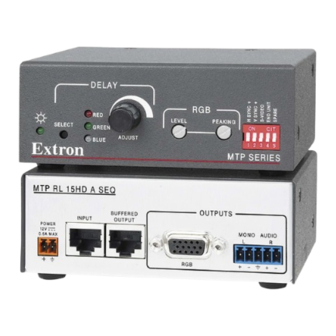
Step 2 — Transmitter Inputs
•
Connect a computer (VGA) video source to the Input connector.
•
Connect a VGA monitor to the Monitor connector.
•
Plug a 3.5 mm stereo audio plug into the audio jack.
Step 3 — TP Cables Between Units
•
Terminate a TP cable as shown at right. Connect it between the transmitter's Output port and
the receiver's Input port.
NOTE:
If the unit is labeled "C7," only CAT 7 cable should be used.
•
For daisy-chaining, connect up to eight TP cables between a receiver's Buffered Output port
and a daisy-chained receiver's Input port.
Step 4 — Receiver Outputs
•
Connect a VGA monitor to the Output connector.
•
Connect a mono audio device to the Mono Audio connector. Wire the connectors as shown
below.
ATTENTION: Connect the sleeves to ground (Gnd).
Connecting the sleeve to a negative (-) terminal will damage the audio
output circuits.
Do not tin the wires!
Step 5 — Receiver DIP Switches
•
H Sync and V. Sync switches — Set these switches up for positive sync or down for negative sync.
•
Composite Sync, (SOG), and Video switches — Set these switches as shown in the table below to
output the indicated format.
Output Format
C Sync
RGBHV
RGBS
RGsB
Component*
S-Video*
Composite*
NOTE: * Input video format must match.
•
End Unit switch — Set this switches up if either of the following is true:
•
The receiver being configured is the only receiver connected to the transmitter.
•
The receiver being configured is the last receiver in a daisy-chained system.
Mono output 1+
Mono output 1
Mono output 1-
NO GROUND.
Sleeve(s)
Mono output 2+
Mono output 2
Mono output 2-
NO GROUND.
Unbalanced Output
SOG
Video
Get other manuals https://www.bkmanuals.com
Sleeve(s)
Balanced Output
AUDIO
INPUT
MONITOR
T568A
T568B
Pin
Wire color
Wire color
Pins:
12345678
1
White-green
White-orange
2
Green
Orange
3
White-orange
White-green
4
Blue
Blue
5
White-blue
White-blue
6
Orange
Green
Insert Twisted
7
White-brown
White-brown
Pair Wires
8
Brown
Brown
NOTE: If you are using Enhanced Skew-Free™ AV
cable, use the TIA/EIA T568A standard only.
MONO AUDIO
1
OUTPUT
ON
1 2 3 4 5 6
2
Advertisement
Table of Contents

Subscribe to Our Youtube Channel
Related Manuals for Extron electronics MTP 15HD A Series


Summary of Contents for Extron electronics MTP 15HD A Series
- Page 1 MTP 15HD A Series • Setup Guide This card provides quick start instructions for an experienced installer to set up and operate any of the MTP VGA video and audio transmission systems. Installation Step 1 — Mounting Turn off or disconnect all equipment power sources and mount the MTP transmitter and up to eight receivers as required.
- Page 2 MTP 15HD A Series • Setup Guide Step 6 — Power POWER xA MAX Rear Wire the 2-pole captive screw connectors for the included external 12 VDC power supplies (see Smooth Panel Ridges image on the right). Plug them into all units.
Need help?
Do you have a question about the MTP 15HD A Series and is the answer not in the manual?
Questions and answers