Advertisement
Quick Links
All numerical values are in metric units [with U.S. customary units in brackets]. Dimensions are in millimeters [and
NOTE
inches]. Unless otherwise specified, dimensions have a tolerance of +0.13 [+.005] and angles have a tolerance of +2_.
i
Figures and illustrations are for identification only and are not drawn to scale.
1. INTRODUCTION
This specification covers the requirements for application of AMP--LATCH Universal Headers with ACTION PIN
Contacts. The headers are available in various positions from 10 through 64. These headers are mounted on a
printed circuit (pc) board by a seating tool which uses various power units for application. The headers are
available with short or long tail contacts and optional ejector latches.
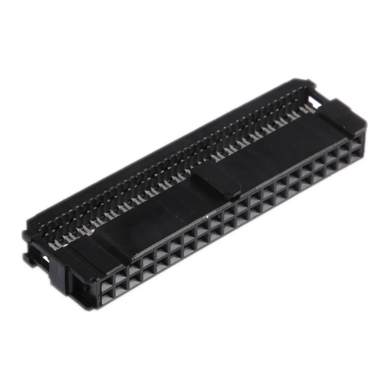
Figure 1 provides contact features and terms used throughout this specification. Use these terms when
corresponding with TE Connectivity Representatives to facilitate assistance.
Ejector Latch
(Optional)
V- - Shaped Indicator
for No. 1 Position
2. REFERENCE MATERIAL
2.1. Revision Summary
This paragraph is reserved for a revision summary covering the most recent additions and changes made to
this specification which include the following:
Updated document to corporate requirements
S
Added new table to Figure 3
S
2.2. Customer Assistance
Reference Part Number 499582 and Product Code 5275 are representative numbers of AMP--LATCH
Universal Headers with ACTION PIN Contacts. Use of these numbers will identify the product line and expedite
your inquiries through a service network established to help you obtain product and tooling information. Such
information can be obtained through a local TE Representative or, after purchase, by calling the Tooling
Assistance Center or the Product Information number at the bottom of this page.
2.3. Drawings
Customer Drawings for each product part number are available from the service network. The information
contained in Customer Drawings takes priority if there is a conflict with this specification or with any technical
documentation supplied by TE.
E2011 Tyco Electronics Corporation, a TE Connectivity Ltd. Company
All Rights Reserved
TE logo is a trademark.
*Trademark. Other product names, logos, or company names might be trademarks of their respective owners.
AMP- LATCH*
Universal Headers
with ACTION PIN* Contacts
ACTION PIN
Contacts
Polarization Slot
TOOLING ASSISTANCE CENTER 1--800--722--1111
PRODUCT INFORMATION 1--800--522--6752
Housing with Universal
Polarizing Slots
Mating End
Termination End
Figure 1
This controlled document is subject to change.
For latest revision and Regional Customer Service,
visit our website at www.te.com
Application Specification
114- - 40020
19 DEC 11 Rev D
Header Assembly
1 of 9
LOC B
Advertisement

Related Manuals for TE Connectivity AMP-LATCH


Summary of Contents for TE Connectivity AMP-LATCH
- Page 1 Customer Drawings takes priority if there is a conflict with this specification or with any technical documentation supplied by TE. 1 of 9 E2011 Tyco Electronics Corporation, a TE Connectivity Ltd. Company TOOLING ASSISTANCE CENTER 1--800--722--1111 This controlled document is subject to change.
- Page 2 114- 40020 2.4. Specifications Product Specification 108--40019 covers test and performance requirements. 2.5. Instructional Material The following list includes available instruction sheets (408--series) that provide assembly procedures for product, operation, maintenance and repair of tooling; and customer manuals (409--series) that provide setup, operation, and maintenance of machines.
-
Page 3: Surface Finish
114- 40020 Refer to Specific Customer Drawing Refer to Specific Customer Drawing See Figure 3 Distance required by ejection latches in the open position. A= 15.37 [.605] with short eject latch A= 17.65 [.695] with long eject latch Datums V and W to be established by customer. Figure 2 D. - Page 4 114- 40020 3.5. Header Spacing Care must be used to avoid interference between adjacent header assemblies and/or other components. The information provided in Figure 4 is to ensure proper clearance for the headers. 6.99 [.275] Minimum Centerline Distance Figure 4 3.6.
- Page 5 114- 40020 3.7. Installed Headers Installed headers must meet the requirements provided in Figure 6. Maximum Post Rotation (Typ): Mating End (2) Termination End (5) Seated Connector Must be Flush to 0.25 [.010] Max. Figure 6 3.8. Keying (Military Applications) Keying plugs can be installed in the connectors to prevent mismating of compatible connectors.
- Page 6 114- 40020 3.9. Mounting Hardware Headers may be secured to the pc board with commercially available 2--56 hardware such as screw, washers, and nuts, self--threading screws, rivets, etc. 3.10. Ejector Latch AMP--LATCH Universal Headers can be used with or without ejector latches. The ejector latches are designed to lock mating connectors together and to ease disengagement of mated connectors.
- Page 7 114- 40020 Machine Ram Flat Rock Tooling Board Customer Supplied PC Board Support Header Assembly Fixture Figure 9 4. QUALIFICATIONS AMP--LATCH Universal Headers are Listed by Underwriters Laboratories Inc. (UL) in File No. E28476, Certified by CSA International in File No. LR 16455, and tested by Verband Deutscher Elektrotechniker (VDE) in File No.
-
Page 8: Header Position
114- 40020 NOTE: Other power units that use seating tools for this product line may be available. Machines that may accommodate your production needs are SM3 Assembly bench machines BMEP- - 3T and BMEP- - 5T; stand 814700- - 2 alone machines MEP- - 6T and MEP- - 12T;... - Page 9 114- 40020 6. VISUAL AID Figure 11 shows a typical application of AMP--LATCH Universal Headers with ACTION PIN Contacts. This illustration should be used by production personnel to ensure a correctly applied product. Applications which DO NOT appear correct should be inspected using the information in the preceding pages of this specification and in the instructional material shipped with the product or tooling.
Need help?
Do you have a question about the AMP-LATCH and is the answer not in the manual?
Questions and answers