
Related Manuals for BUSCH COBRA DX 0650 A


Summary of Contents for BUSCH COBRA DX 0650 A
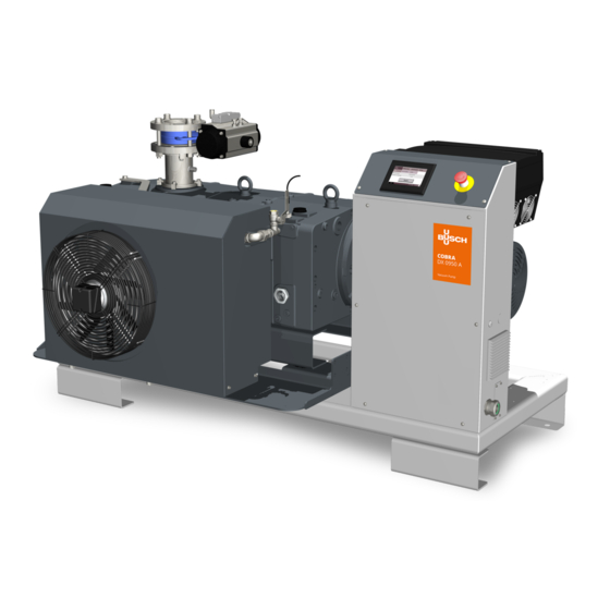
- Page 1 COBRA Dry Screw Vacuum Pumps DX 0650 A, DX 0950 A Air-Cooled Version (ACV) Instruction Manual 2000090907 | -_en-US | Original instructions 6/14/2023...
-
Page 2: Table Of Contents
Table of Contents Table of Contents Safety ..................................Product Description ............................. Operating Principle ............................. Intended Use ............................... Standard Features............................... 2.3.1 Air Cooling ............................. 2.3.2 Temperature Switch ..........................2.3.3 Sealing Systems ............................ Optional Accessories............................2.4.1 Gas Ballast Valve........................... 2.4.2 Silencer ..............................2.4.3 Barrier Gas System.......................... - Page 3 Table of Contents Cleaning the Silencer (Optional)........................Oil Change................................Cooling Liquid Change ............................Overhaul ................................Decommissioning ..............................10.1 Dismantling and Disposal ..........................Troubleshooting ..............................Technical Data ..............................Oil ................................... Cooling Liquid ............................... EU Declaration of Conformity ..........................UK Declaration of Conformity..........................Instruction Manual COBRA DX 0650-0950 A ACV_EN_en 3 | 64...
-
Page 4: Safety
Safety Prior to handling the machine, this instruction manual should be read and understood. If anything needs to be clarified, please contact your Busch representative. Read this manual carefully before use and keep for future reference. This instruction manual remains valid as long as the customer does not change anything on the product. -
Page 5: Product Description
Product Description | 2 Product Description NOTE Illustrations. In this instruction manual, the machine illustrations are of the COBRA DX 0950 A. Although they differ from the COBRA DX 0650 A, the principles and operation are similar. EPIV GBS GB CLV1 CLV2... - Page 6 2 | Product Description Description Barrier gas pressure regulator (PRV) – op- Solenoid valve (Barrier gas) – option* tion* Condensate drain Communication I/O port - option Control unit Cooling liquid drain plug Cooling liquid fill plug Cooling liquid pump CLV1 Cooling liquid vent valve (Heat exchanger) CLV2 Cooling liquid vent plug (Machine)
-
Page 7: Operating Principle
Busch. The machine is intended for indoor placement in a non-potentially explosive environment. The machine is designed for indoor installations. For outdoor installations, consult your Busch repre- sentative for special precautions. The machine is capable of maintaining ultimate pressure, see Technical Data. -
Page 8: Standard Features
2 | Product Description Standard Features 2.3.1 Air Cooling The machine is cooled by a cooling liquid circuit in the cylinder cover and cylinder. The cooling liquid pump (CLP) allows a recirculating flow in the cooling liquid chamber. The cooling liquid is cooled by an air-water heat exchanger (AHE). * T cooling liquid Description Suction connection (Inlet) -
Page 9: Optional Accessories
CAUTION Electro-pneumatic inlet valve pressure. Risk of injuries! Risk of damage to the machine! ● Busch recommends the installation of a pressure sensor with the following range and accuracy values. Pressure sensor range and accuracy Range: 0-1000 mbar Accuracy: +/- 7.0 mbar NOTE To actuate the valve, compressed air or nitrogen must be supplied. -
Page 10: Otto Iot Box
2.4.5 OTTO IoT Box The machine can be equipped with the OTTO IoT Box. It allows the vacuum pump to be connected to the Busch Cloud and collect live measured data during its operation. The IoT system consists in: ● The IoT Box ●... - Page 11 Product Description | 2 NOTE In case of a remote-control start, the machine must be integrated in the user's safety chain (signal warning the user to stop the machine in case of problem or emergency stop). NOTE Standard factory setting: Bridge on terminals 24VDC / 24 inside the Control Unit (CU). Remove the bridge and connect to Remote pump start.
- Page 12 2 | Product Description External Contact (Pump Status) ● M12 connector Max 30VAC/DC 1.5A ● On terminal Max 250VAC/DC 10A NOTE System error, chain safety, EMO. This contact gives information about the status of the machine and changes its status if an event such as an error, a thermal fault or an emergency stop occurs.
-
Page 13: Main Power Switch / Breaker
Product Description | 2 2.4.7 Main Power Switch / Breaker The machine can be equipped with a power switch to turn it on and off. In case this power switch is not installed, an equivalent device must be installed in the customer's system. -
Page 14: Transport
3 | Transport Transport WARNING Suspended load. Risk of severe injury! ● Do not walk, stand or work under suspended loads. WARNING Lifting the machine using the motor eye bolt. Risk of severe injury! ● Do not lift the machine using the eye bolt fitted to the motor. Only lift the machine as shown. NOTICE In case the machine is already filled with oil. -
Page 15: Storage
Storage | 4 Storage ● Seal all apertures with adhesive tape or reuse provided caps. NOTICE Long storage time. Risk of damage to the machine! ● Due to a long storage time the capacitors of the variable speed drive can lose efficiency because of electrochemical processes. -
Page 16: Installation
● Check the cooling liquid level, see Cooling Liquid Level Inspection [➔ 47]. If the machine is installed at an altitude greater than 1000 meters above sea level: ● Contact your Busch representative, the motor should be derated or the ambient temperature limited. -
Page 17: Connecting Lines / Pipes
– Inlet filter: ISO-K DN100, DIN 28404 If the machine is used as part of a vacuum system: ● Busch recommends the installation of an isolation valve in order to prevent the machine from turning backwards. ● Make sure that the connection lines cause no stress on the connections of the machine. There- fore, we recommend installing flexible joints on the suction and discharge connections. -
Page 18: Discharge Connection
5 | Installation 5.2.2 Discharge Connection Description Standard exhaust without silencer (SI) Bottom view of the machine Auxiliary port NOTICE Discharge gas flow obstructed. Risk of damage to the machine! ● Make sure that the discharged gas will flow without obstruction. Do not shut off or throttle the discharge line or use it as a pressurized air source. -
Page 19: Barrier Gas System Connection (Optional)
Installation | 5 5.2.3 Barrier Gas System Connection (Optional) Description Barrier gas connection Flow meter Manometer Solenoid valve Pressure regulating valve ● Connect the barrier gas connection (BGC) to the gas supply. Connection size: – G1/4, ISO 228-1 ● Make sure that the gas complies with the following requirements: Gas type Dry nitrogen or air Gas temperature... -
Page 20: Electro-Pneumatic Inlet Valve Connection (Optional)
5 | Installation 5.2.4 Electro-Pneumatic Inlet Valve Connection (Optional) Description Electro-pneumatic inlet valve (EPIV) Compressed air or nitrogen intake Connection size: ● DN100 ISO-K The electro-pneumatic inlet valve (EPIV) must be connected to compressed air or compressed nitro- gen gas source. ●... -
Page 21: Filling Oil
Risk of premature failure! Loss of efficiency! ● Only use an oil type which has previously been approved and recommended by Busch. For oil type and oil capacity see Technical Data and Oil [➔ 59]. Instruction Manual COBRA DX 0650-0950 A ACV_EN_en... -
Page 22: Cooling System Cover Removal
When the oil filling is achieved: ● Write down the oil change date on the sticker. If there is no sticker (part no. 0565 568 959) on the machine: ● Order it from your Busch representative. Cooling System Cover Removal NOTE Before filling or changing the cooling liquid and electrically connecting the cooling system. -
Page 23: Filling Cooling Liquid
Installation | 5 Filling Cooling Liquid The machine is already dispatched with cooling liquid. If it is not the case: ● Electrically connect the cooling system, see Electrical Connection of the Cooling System [➔ 28]. ● Fill in the machine with cooling liquid according to the following procedure. For cooling liquid type and cooling liquid capacity see Technical Data and Cooling Liquid [➔ 60]. -
Page 24: Electrical Connection
● Make sure that the motor of the machine will not be affected by electric or electromagnetic dis- turbance from the mains, if necessary seek advice from Busch. ● Make sure that the EMC of the machine is compliant with the requirements of your supply net- work system, if necessary provide further interference suppression (EMC of the machine, see EU Declaration of Conformity [➔ 61] or UK Declaration of Conformity [➔ 62]). -
Page 25: Machine Delivered With A Control Unit
● If the machine is equipped with a power connector, install a residual current protective device to protect persons in case of a defective insulation. ● Busch recommends installing a type B residual protective device suitable for the electrical in- stallation. -
Page 26: Machine Delivered With A Variable Speed Drive
● If the machine is equipped with a power connector, install a residual current protective device to protect persons in case of a defective insulation. ● Busch recommends installing a type B residual protective device suitable for the electrical in- stallation. -
Page 27: Main Power Supply Connection
Electrical Connection | 6 ● Provide an overload protection according to EN 60204-1. ● Busch recommends installing a C-curve circuit breaker. ● Connect the protective earth conductor. ● Electrically connect the machine to the main power supply. Main Power Supply Connection Cable gland size of the power input: –... -
Page 28: Modbus Control And Ethernet Settings (Optional)
6 | Electrical Connection Plug Maximum current 80A @ 40°C Maximum voltage 480V Square cable sq 1.5 … 16mm AWG gauge AWG 16 … 6 Cable entry M32x1.5mm Modbus Control and Ethernet Settings (Optional) The user interface (HMI) works in Modbus with “Holding Registers”, readable and writable, 16 bits. The default ethernet settings are the following: Description Default value... - Page 29 Electrical Connection | 6 Instruction Manual COBRA DX 0650-0950 A ACV_EN_en 29 | 64...
-
Page 30: Commissioning
7 | Commissioning Commissioning CAUTION During operation the surface of the machine may reach temperatures of more than 70°C. Risk of burns! ● Avoid contact with the machine during and directly after operation. CAUTION Noise of running machine. Risk of damage to hearing! If people are present in the vicinity of a machine that is not insulated from noise for extended peri- ods of time: ●... -
Page 31: Description Of User Interface Functions
Commissioning | 7 As soon as the machine is operated under normal operating conditions: ● Measure the motor current and record it as reference for future maintenance and trouble- shooting work. Description of User Interface Functions The following functions and parameters are available on the TOUCH SCREEN - HMI interface: ●... -
Page 32: Roles And Users
● reset hours before the next service, ● set the remote control and monitoring parameters. Role 3 ► Busch Service Only authorized personnel from Busch Service have this level of access rights. NOTE In case of any questions related to the machine settings: ●... -
Page 33: Home
Commissioning | 7 7.1.2 Home 7.1.2.1 Main The display “HOME > MAIN” is the main display. It is mainly useful for live monitoring. 7.1.2.2 Monitoring (Operating Data) The display “HOME” > “MONITORING” shows the operating values. It is divided into three different screens/pages. Screen/Page MONITORING 1 Instant absorbed power. - Page 34 7 | Commissioning Screen/Page MONITORING 2 Inlet pressure. Indicates the pressure at the inlet of the pump when the pump is equipped with the inlet valve and when the function is activated. Motor frequency. Indicates in Hz the current drive frequency. IGBT temperature.
-
Page 35: Operations
Commissioning | 7 7.1.2.3 Alarms The display “HOME” > “ALARM” shows the history of the alarms’ signals registered by the pump mon- itoring sensors. When an alarm occurs, an audible alarm sounds, and the user must acknowledge the default on the HMI interface. - Page 36 <5 ... 1000 mbar ● For smooth process pressure control, it is required to adjust the PID parameters. ● For more information, contact your Busch representative. Ecomode (Option - function associated to the Pressure control). The Ecomode stops the machine when the inlet pressure has reached the preset "ecomode pres- sure"...
- Page 37 Change parameter values. Risk of damage to the machine! ● For all the following functions with parameterization, Busch strongly recommends waiting until the end of a pump cycle before changing any parameter value! The display “OPERATIONS > PARAMETERS” shows the operation parameters.
- Page 38 7 | Commissioning During these phases, the machine operates at maximum speed, recommended with the gas ballast valve open to warm up and evacuate a maximum of humidity. The warm-up mode and the cool-down* mode (*shutdown/drying) can both be set with a target time (default value = 30 minutes).
- Page 39 Vacuum booster compatibility. Risk of damage to the machine! ● Contact Busch to check the compatibility of the vacuum booster with the vacuum pump and the recommended starting pressure. This menu allows the control and setting of the start-up parameters of a vacuum booster installed at the suction side of the vacuum pump (not included in the scope of delivery of the vacuum pump).
-
Page 40: Maintenance
7 | Commissioning 7.1.4 Maintenance The display “MAINTENANCE” shows the maintenance and service intervals of the machine. 7.1.5 System 7.1.5.1 System Settings The display “SYSTEM > SETTING” allows to set or change system settings. Screen/Page SETTING 1 ● To edit the system settings such as date, time, language, and units: ●... - Page 41 Commissioning | 7 Screen/Page SETTING 2 On the second screen/page, it is possible to edit some pump parameters like the pressure control settings (PID) or to activate/deactivate pump functions like the pressure sensor (Option) or OTTO. Screen/Page SETTING 3 On the third screen/page, it is possible to access the internal settings of the HMI by pressing the button for two seconds.
- Page 42 7 | Commissioning 7.1.5.2 Model The "SYSTEM > MODEL" display provides information on the identification of the software and the machine (type and model on screen/page 1, serial number on screen/page 2). Screen/Page MODEL 1 Screen/Page MODEL 2 42 | 64 Instruction Manual COBRA DX 0650-0950 A ACV_EN_en...
- Page 43 Commissioning | 7 7.1.5.3 Ethernet Settings ● To configure the ethernet settings according to your network: ● Go to “SYSTEM” > “ETHERNET”. ● Change the values on the right side of the screen (Change settings). ● Press on the switch button to save the new settings. NOTE The current Ethernet values are displayed in the left side of the screen (Ethernet settings).
-
Page 44: Conveying Condensable Vapors
(e.g. "dead leg") with drain. ● Water vapor within the gas flow is tolerated within certain limits. The conveyance of other vapors shall be agreed upon with Busch. 44 | 64 Instruction Manual COBRA DX 0650-0950 A ACV_EN_en... -
Page 45: Maintenance
Maintenance | 8 Maintenance DANGER Live wires. Risk of electrical shock. ● Electrical installation work must only be executed by qualified personnel. DANGER Maintenance work without disconnecting the variable speed drive. Risk of electrical shock. ● Disconnect and isolate the variable speed drive before attempting any work on it. High voltages are present at the terminals and within the variable speed drive for up to 10 min- utes after disconnection of the electrical supply. -
Page 46: Maintenance Schedule
Risk of injuries! Risk of premature failure and loss of efficiency! ● Maintenance work must only be executed by qualified personnel. ● Respect the maintenance intervals or ask your Busch representative for service. NOTICE Using inappropriate cleaners. Risk of removing safety stickers and protective paint! ●... -
Page 47: Oil Level Inspection
● Change the cooling liquid, see Cooling Liquid Change [➔ 52]. ● Clean the magnetic plugs (MP). Every 25000 hours or after 4 ● Have a major overhaul on the machine (contact Busch). years Oil Level Inspection ● Shut down the machine. -
Page 48: Cleaning The Gas Ballast Filter (Optional)
8 | Maintenance Cleaning the Gas Ballast Filter (Optional) Description Use a 36 mm wrench Use compressed air and wear protec- tive eyewear and mask Cleaning the Silencer (Optional) Description Bottom view of the machine Unscrew the 4 hexagonal screws to re- move the silencer 48 | 64 Instruction Manual COBRA DX 0650-0950 A ACV_EN_en... -
Page 49: Oil Change
NOTICE Use of an inappropriate oil. Risk of premature failure! Loss of efficiency! ● Only use an oil type which has previously been approved and recommended by Busch. Description Magnetic plug Instruction Manual COBRA DX 0650-0950 A ACV_EN_en 49 | 64... - Page 50 8 | Maintenance Description Magnetic plug For oil type and oil capacity see Technical Data and Oil [➔ 59]. 50 | 64 Instruction Manual COBRA DX 0650-0950 A ACV_EN_en...
- Page 51 ● Write down the oil change date on the sticker. If there is no sticker (part no. 0565 568 959) on the machine: ● Order it from your Busch representative. Instruction Manual COBRA DX 0650-0950 A ACV_EN_en 51 | 64...
-
Page 52: Cooling Liquid Change
8 | Maintenance Cooling Liquid Change For cooling liquid type and cooling liquid capacity see Technical Data and Cooling Liquid [➔ 60]. 52 | 64 Instruction Manual COBRA DX 0650-0950 A ACV_EN_en... - Page 53 Maintenance | 8 Description Step 4: Open the cooling liquid vent Step 6: Switch on the cooling liquid valves (CLV1, CLV2) pump (CLP) Step 7: Vent air from the cooling sys- Step 8: Close the cooling liquid vent valve (CLV2) when the cooling liquid is spilling out Step 9: Resume cooling liquid filling Step 10: Close the cooling liquid vent...
-
Page 54: Overhaul
● Decontaminate the machine as much as possible and state the contamination status in a ‘Dec- laration of Contamination’. Busch will only accept machine that comes with a completely filled in and legally binding signed ‘Declaration of Contamination’ (form downloadable from www.buschvacuum.com). -
Page 55: Decommissioning
Decommissioning | 10 Decommissioning DANGER Live wires. Risk of electrical shock. ● Electrical installation work must only be executed by qualified personnel. CAUTION Hot surface. Risk of burns! ● Before doing anything that requires touching the machine, let it cool down first. ●... -
Page 56: Troubleshooting
Solid foreign matter has en- ● Remove the solid foreign tered the machine. matter or repair the ma- chine (contact Busch). Alarm trip of the monitoring ● Let the machine cool down. sensors or the variable speed ● Check the Event log on the drive. - Page 57 Oil Change [➔ 49]. The machine runs too hot. ● See problem "The machine runs too hot". For resolution of problems not listed in the troubleshooting table, please contact your Busch repre- sentative. Instruction Manual COBRA DX 0650-0950 A ACV_EN_en 57 | 64...
-
Page 58: Technical Data
12 | Technical Data Technical Data DX 0650 A DX 0950 A Pumping speed m³/h Ultimate pressure hPa (mbar) abs. ≤0.1 ≤0.01 (Without gas ballast) Ultimate pressure (With gas ballast) hPa (mbar) abs. ≤0.5 ≤0.05 Nominal motor rating 15 (50 Hz) 18.5 Nominal motor speed 3000 (50 Hz) -
Page 59: Oil
Oil | 13 VSC 100 ISO-VG Oil type Synthetic Part number 1 L packaging 0831 168 356 Part number 5 L packaging 0831 168 357 Part number 10 L packaging 0831 210 162 Part number 20 L packaging 0831 168 359 Oil suitability ● Oil VSC 100: Suitable for harsh applications. Instruction Manual COBRA DX 0650-0950 A ACV_EN_en 59 | 64... -
Page 60: Cooling Liquid
14 | Cooling Liquid Cooling Liquid Zitrec M-25 (ready-to-use) Part number 5 L packaging 0831 563 469 Part number 20 L packaging 0831 238 761 The cooling liquid Zitrec M-25 is ready-to-use and does not require additional water. For further information, consult the website www.arteco-coolants.com. 60 | 64 Instruction Manual COBRA DX 0650-0950 A ACV_EN_en... -
Page 61: Eu Declaration Of Conformity
EU Declaration of Conformity This Declaration of Conformity and the CE-markings affixed to the nameplate are valid for the machine within the Busch scope of delivery. This Decla- ration of Conformity is issued under the sole responsibility of the manufacturer. -
Page 62: Declaration Of Conformity
UK Declaration of Conformity This Declaration of Conformity and the UKCA-markings affixed to the nameplate are valid for the machine within the Busch scope of delivery. This Dec- laration of Conformity is issued under the sole responsibility of the manufacturer. - Page 63 N otes Notes Instruction Manual COBRA DX 0650-0950 A ACV_EN_en 63 | 64...
- Page 64 With a network of over 60 companies in more than 40 countries and agencies worldwide, Busch has a global presence. In every country, highly competent local personnel delivers custom-tailored support backed by a global network of expertise. Wherever you are.
Need help?
Do you have a question about the COBRA DX 0650 A and is the answer not in the manual?
Questions and answers