
Subscribe to Our Youtube Channel
Related Manuals for BUSCH COBRA DS 9161 B


Summary of Contents for BUSCH COBRA DS 9161 B
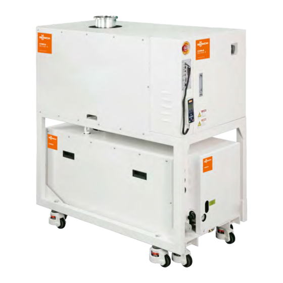
- Page 1 Instruction Manual COBRA Combi Screw Vacuum Pumps and Boosters DS 9161 B 0870772604/-0008_en / Original instructions 21/10//2021...
- Page 2 UK-Declaration of Conformity......31 Preface worldwide. Preface Page 2 0870772604...
- Page 3 COBRA DS 9161 B MSH Main switch Backing vacuum pump DP 600 C PTB Pump terminal box Emergency stop switch VFD Roots frequency inverter Inlet Roots WY 075 COBRA DS 9161 B Page 3 0870772604...
- Page 4 FME Flow meter, nitrogen TS 4 Temperature switch, oil temperature 140°C TS 5 Overpressure sensor FS 1 Flow switch, cooling liquid TS 6 Temperature switch, motor 155°C FS 2 Flow switch, cooling water Heat exchanger COBRA DS 9161 B Page 4 0870772604...
- Page 5 FS 3 Flow switch, cooling water Inlet ODP Oil drain plug OFP Oil filler plug OSG Oil sight glass OUT Discharge/ Distribution for DP pump RSG Rotation sight glass VFD Roots frequency inverter COBRA DS 9161 B Page 5 0870772604...
- Page 6 PLCM DS 9161 B with equipment BUPS Back up power supply Ground EOCR Electronic Over Current Relay Magnetic contactor No Fuse Breaker PLCM PLC module DC Power supply unit Rotation sensor EOCR BUPS COBRA DS 9161 B Page 6 0870772604...
- Page 7 TS 2 Temperature switch, cooling liquid temperature 100° TS 3 Temperature switch PT100 TS 4 Temperature switch, oil temperature 140°C TS 5 Overpressure sensor TS 6 Temperature switch, motor 155°C TS 7 Temperature switch, motor MB COBRA DS 9161 B Page 7 0870772604...
-
Page 8: Product Description
2) Start MB: The WY Roots pump will starts after the DP1 when the delay of the timer “MB ON DELAY” is done (timer settable in the settings, nomally at 30s). If there are several WY Roots, they start together. Product description COBRA DS 9161 B Page 8 0870772604... -
Page 9: Nitrogen System
(8) is preset at 40 l/ min and can be adjusted with valve DGR 2, depending on the application. When flow is too low a warning then an alarm signal is generated by COBRA DS 9161 B Product description Page 9... - Page 10 The operator of the vacuum system must observe the safety regula- tions and must train and instruct his personnel accordingly. Safety COBRA DS 9161 B Page 10 0870772604...
-
Page 11: Noise Emission
Equipment is energized. Energized circuits are covered or insulated. NOTE : Type 2 work includes tasks where the energized circuits are or can be measured by placing probes through suitable openings in the covers or insulators. Safety COBRA DS 9161 B Page 11 0870772604... - Page 12 If ok, check the wiring system from the terminal box motor to the overtempera- switch TS 7 KDP1 contactor. If ok, call the BUSCH Semicon service team in ture (t° > charge of the maintenance of the pumps. 150°C) l Before restarting the vacuum system, reactivate the FDP1 thermal relay by pressing on Reset.
- Page 13 The contactors open and cut temperature switch TS 1 the engine supply after 120 (t°>105°C) seconds (changeable dura- tion) H= Hardware, S= Software “X” is the number of the DP or MB vacuum pump Safety COBRA DS 9161 B Page 13 0870772604...
- Page 14 Use a hoist that is equipped with a hook and safety lock – indoors, l Lift the vacuum system Transportation COBRA DS 9161 B Page 14 0870772604...
-
Page 15: Installation And Start-Up
Make sure that the nitrogen fulfills the following requirements: l Set the vacuum system on as level, horizontal surface. – Overpressure: 1,5 bar – Approximate flow rate: 0 - 200 l/ min Installation and start-up COBRA DS 9161 B Page 15 0870772604... -
Page 16: Inlet Connection
If the sucked gas contains dusts or solid foreign bodies: of the vacuum system. If you have any doubts, contact your Busch representative. u Make sure that a filter or protective grating is installed at the... -
Page 17: Electrical Connection/ Checks
Make sure that an overload cut-out according to EN 60204-1 is provided for the motor l Make sure that the drive of the vacuum system is not disturbed by any electric or electromagnetic interferences. If you have any doubts, contact your Busch representative CAUTION Ground Overvoltage damages the vacuum system! -
Page 18: Equipment Connections (With Options)
Remove the rubber plate from the intake flange and connect the PID interface (9 poles) (option) intake line to the intake flange The information concerning the use of the Busch PLC and the Busch Checking the direct cooling LCD can be found in the Operation and Maintenance Instructions (Art-No. - Page 19 If these conditions are not met, there is a risk of damage to or total l Screw on the oil filler cap hermetically tight destruction of the vacuum system and its components! The vacuum system may only be switched on under the specified conditions. Installation and start-up COBRA DS 9161 B Page 19 0870772604...
- Page 20 Supply voltage is switched on liquid. l The vacuum system is switched on by the LCD or interface box. Operation without cooling liquid will result in damage to the vacuum system! Installation and start-up COBRA DS 9161 B Page 20 0870772604...
-
Page 21: Monitoring Equipment
(rapid cooling of the vacuum pump wished or not) – put the label or warning board “Maintenance processing” on or next to the vacuum system Maintenance COBRA DS 9161 B Page 21 0870772604... -
Page 22: Maintenance Program
Drain the oil (see "Draining the oil") – switch on the water (outlet first, then inlet) and nitrogen quick connections l Main inspection of the vacuum system (Busch) – make sure that the "Necessary installation instructions" are Lock Out/ Tag out procedure followed –... -
Page 23: Checking The Oil Level
If dark oil similar to the example shown is observed, you have to contact the Busch Customer Service without delay. l Make sure that the oil level is in the target circle of the oil sight... - Page 24 B-side as the cooling liquid will flow out- l Unscrew the oil drain plugs again and drain the remaining oil side otherwise follow the procedure Checking the oil COBRA DS 9161 B Page 24 0870772604...
-
Page 25: Checking The Leak-Protection Non-Return Valve (Accessory)
("Declaration of Decontamina- tion"), which can be downloaded from www.buschvacuum.com. Checking the nitrogen Busch service will only accept vacuum pumps that come with a com- Checking the nitrogen flow pletely filled in and legally binding signed form. -
Page 26: Dismantling And Disposal
A lithium battery is present inside the PLC: eliminate the lithium battery according to local and national regulations in place, relating to environment Removal from service COBRA DS 9161 B Page 26 0870772604... -
Page 27: Oil Type/ Quantity
Make sure that the oil type corresponds to specification: – Busch YLC 250 B, Art. No. 0831 131 400 (0,5 l @ 1 kg) WARNING The use of chemically contaminated or polluted oil can lead to hazardous pump conditions which could cause personal injury. -
Page 28: Cooling Liquid Type
But when using pure glycol, it is imperative to prepare the mix prior to filling the pump and to respect this proportion. Cooling liquid type/ quantity (DP only) COBRA DS 9161 B Page 28 0870772604... -
Page 29: Technical Data
13 (motors cooling) Cooling water pressure bar/ DP 2 ... 5 Cooling water temperature °C 10 - 25°C Nitrogen requirement approx. l/ min 0 - 200 Nitrogen overpressure Weight approx. 1800 Technical data COBRA DS 9161 B Page 29 0870772604... -
Page 30: Eu Declaration Of Conformity
This Declaration of Conformity and the CE-mark affixed to the nameplate are valid for the machine within the Busch scope of delivery. This Declaration of Conformity is issued under the sole responsibility of the manufacturer. When this machine is integrated into a superordinate machinery the manufacturer of the superordinate machinery (this can be the operating company, too) must conduct the conformity assessment process for the superordinate machine or plant, issue the Declaration of Conformity for it and affix the CE-mark. - Page 31 This Declaration of Conformity and the UKCA-mark affixed to the nameplate are valid for the machine within the Busch scope of delivery. This Declaration of Conformity is issued under the sole responsibility of the manufacturer. When this machine is integrated into a superordinate machinery the manufacturer of the superordinate machinery (this can be the operating company, too) must conduct the conformity assessment process for the superordinate machine or plant, issue the Declaration of Conformity for it and affix the UKCA-mark.
- Page 32 Busch Vacuum Solutions We shape vacuum for you. Argentina Denmark Malaysia South Africa info@busch.com.ar info@busch.dk busch@busch.com.my info@busch.co.za Australia Finland Mexico Spain sales@busch.com.au info@busch.fi info@busch.com.mx contacto@buschiberica.es Austria France Netherlands Sweden busch@busch.at busch@busch.fr info@busch.nl info@busch.se Bangladesh Germany New Zealand Switzerland sales@busch.com.bd info@busch.de sales@busch.co.nz...
Need help?
Do you have a question about the COBRA DS 9161 B and is the answer not in the manual?
Questions and answers