
Related Manuals for BUSCH COBRA PLUS DX 2000 A PLUS


Summary of Contents for BUSCH COBRA PLUS DX 2000 A PLUS
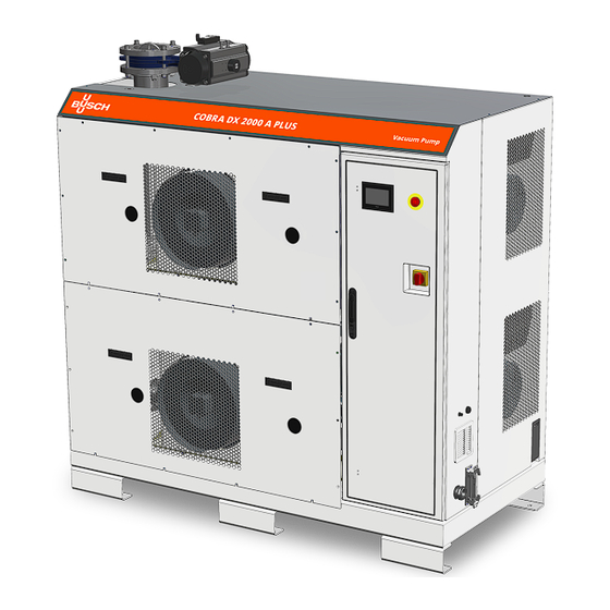
- Page 1 COBRA PLUS Dry Screw Vacuum Pumps DX 2000 A PLUS Air-Cooled Version (ACV) Instruction Manual 2000191879 | -_en-US | Original instructions 4/18/2024...
-
Page 2: Table Of Contents
Table of Contents Table of Contents Safety ..................................Product Description ............................. Operating Principle ............................. Intended Use ............................... Start Controls............................... Standard Features............................... 2.4.1 Air Cooling ............................. 2.4.2 Temperature Switch ..........................2.4.3 Sealing Systems ............................ Optional Accessories............................2.5.1 Gas Ballast Valve........................... 2.5.2 Silencer .............................. - Page 3 Table of Contents Cleaning the Gas Ballast Filter (Optional) ......................Cleaning the Silencer (Optional)........................Oil Change................................Cooling Liquid Change ............................Overhaul ................................Decommissioning ..............................10.1 Dismantling and Disposal ..........................Troubleshooting ..............................Technical Data ..............................Oil ................................... Cooling Liquid ............................... EU Declaration of Conformity ..........................UK Declaration of Conformity..........................
-
Page 4: Safety
Safety Prior to handling the machine, this instruction manual should be read and understood. If anything needs to be clarified, please contact your Busch representative. Read this manual carefully before use and keep for future reference. This instruction manual remains valid as long as the customer does not change anything on the product. -
Page 5: Product Description
● See Description of User Interface Functions [➔ 40]. WARNING Each of the two machines has a differently programmed variable speed drive and cannot therefore be exchanged without the intervention of Busch representatives! Instruction Manual COBRA DX 2000 A PLUS ACV_EN_en 5 | 80... - Page 6 2 | Product Description COBRA DX 2000 A PLUS with cabinet (Option) EPIV CU HMI 6 | 80 Instruction Manual COBRA DX 2000 A PLUS ACV_EN_en...
- Page 7 Product Description | 2 Description Suction connection (Inlet) Discharge connection (Outlet) Acoustic cabinet - option Base frame Barrier gas connection – option* Cooling air inlet Cooling air outlet Communication I/O port - option Control unit EPIV Electro-pneumatic inlet valve - option Emergency stop switch User interface (human-machine) LAN Communication port (Modbus TCP/IP) -...
- Page 8 2 | Product Description Interior of the COBRA DX 2000 A PLUS with optional cabinet removed CLV1, CLV2 EPIV OFP, 8 | 80 Instruction Manual COBRA DX 2000 A PLUS ACV_EN_en...
- Page 9 Product Description | 2 Description "Pilot" vacuum pump (Pump #1) "Follower" vacuum pump (Pump #2) On each vacuum pump (Suction side) On each vacuum pump (Motor side) Description Suction connection (Inlet) Discharge connection (Outlet) Air deflector (DX 2000 A PLUS with cabinet Air-water heat exchanger only) Axial fan...
-
Page 10: Operating Principle
2 | Product Description COBRA DX 2000 A PLUS without cabinet (Standard) Accessories for the DX 2000 A PLUS without cabinet are the same as for the interior of the DX 2000 A PLUS with optional cabinet, except that the air deflectors (AD) are replaced by the cooling system covers shown below. -
Page 11: Intended Use
Busch. The machine is intended for indoor placement in a non-potentially explosive environment. The machine is designed for indoor installations. For outdoor installations, consult your Busch repre- sentative for special precautions. The machine is capable of maintaining ultimate pressure, see Technical Data. -
Page 12: Temperature Switch
2 | Product Description Description COBRA NX 0950 A air cooling system * T cooling liquid (Valid for each COBRA NX 0950 A ma- chine inside the DX 2000 A PLUS) Description Suction connection (Inlet) Discharge connection (Outlet) Air-water heat exchanger Cooling liquid pump Coupling MOT1... -
Page 13: Barrier Gas System
OTTO IoT Box The machine can be equipped with the OTTO IoT Box. It allows the vacuum pump to be connected to the Busch Cloud and collect live measured data during its operation. Instruction Manual COBRA DX 2000 A PLUS ACV_EN_en... -
Page 14: I/O And Communication Port
● A GSM antenna ● Sensors (Pressure sensor, resistance thermometer, vibration sensor) For the activation and setup of this optional function, please contact your Busch representative. For any additional information, refer to the specific document “OTTO IoT Box User's Manual, art. no. - Page 15 Product Description | 2 Power Supply ● 24VDC power supply - Max 1.5A Remote Pump Start It allows the machine to be started by an external signal. If pins 1 and 10 are bridged, the machine will start according to the settings of the HMI. NOTE In case of a remote-control start, the machine must be integrated in the user's safety chain (signal warning the user to stop the machine in case of problem or emergency stop).
- Page 16 2 | Product Description External Safety Switch It allows to add an external safety element. Remove the bridge and put a dry contact instead. NOTE The bridge is mandatory in case of a remote-control use. NOTE According to the standard factory setting, there is a bridge on the terminals inside the control unit (CU).
-
Page 17: Main Power Switch / Breaker
Product Description | 2 ● Activation according to the settings of the HMI. Modbus Control For more information: ● See Modbus Control and Ethernet Settings [➔ 37]. 2.5.7 Main Power Switch / Breaker The machine can be equipped with a power switch to turn it on and off. In case this power switch is not installed, an equivalent device must be installed in the customer's system. -
Page 18: Industrial Quick Connector
2 | Product Description 2.5.8 Industrial Quick Connector The standard version of the machine is equipped with a cable gland (PWS). The machine can be equipped with an industrial quick connector (see Main Power Supply Connection [➔ 36]). 18 | 80 Instruction Manual COBRA DX 2000 A PLUS ACV_EN_en... -
Page 19: Transport
Transport | 3 Transport WARNING Transport by truck, train, boat, or plane. Risk of severe injury! Risk of falling! Risk of slipping! ● When transporting by truck, train, boat, or plane, the pallet must be securely fastened to prevent it from falling or slipping. WARNING Suspended load. - Page 20 3 | Transport Transport with a forklift WARNING Weight of the machine: 2450 kg without cabinet, 2600 kg with cabinet. Risk of severe injury! Handle with care! ● Due to the weight of the machine, make sure to use a suitable forklift truck. ●...
-
Page 21: Storage
Storage | 4 Storage ● Seal hermetically all apertures with the caps provided with the machine, or with adhesive tape if the caps are no longer available. ● Store the machine indoors, in a dry place, away from dust and vibrations and if possible, in original packaging, preferably at temperatures between 0 ... -
Page 22: Installation
5 | Installation Installation Installation Conditions NOTICE Use of the machine outside of the permitted installation conditions. Risk of premature failure! Loss of efficiency! ● Make sure that the installation conditions are fully respected. Description With cabinet (Option) Top side: no requirement Back side: can be installed against a Right side: min. - Page 23 ● Check the cooling liquid level, see Cooling Liquid Level Inspection [➔ 58]. If the machine is installed at an altitude greater than 1000 meters above sea level: ● Contact your Busch representative, the motor should be derated or the ambient temperature limited.
-
Page 24: Connecting Lines / Pipes
– Inlet filter: ISO-K DN160, DIN 28404 If the machine is used as part of a vacuum system: ● Busch recommends the installation of an isolation valve in order to prevent the machine from turning backwards. ● Make sure that the connection lines cause no stress on the connections of the machine. There- fore, we recommend installing flexible lines on the suction and discharge connections. -
Page 25: Discharge Connection
Installation | 5 5.2.2 Discharge Connection Description Standard exhausts without silencers Bottom view of the DX 2000 A PLUS (SI) Auxiliary port (one on each NX 0950 A) NOTICE Discharge gas flow obstructed. Risk of damage to the machine! ● Make sure that the discharged gas will flow without obstruction. Do not shut off or throttle the discharge line or use it as a pressurized air source. -
Page 26: Barrier Gas System Connection (Optional)
5 | Installation 5.2.3 Barrier Gas System Connection (Optional) Description "Pilot" vacuum pump (Pump #1) "Follower" vacuum pump (Pump #2) Description Barrier gas connection Flow meter Manometer Solenoid valve Pressure regulating valve ● Connect the barrier gas connection (BGC) to the gas supply. Connection size: –... -
Page 27: Electro-Pneumatic Inlet Valve Connection (Optional)
Installation | 5 5.2.4 Electro-Pneumatic Inlet Valve Connection (Optional) Description Electro-pneumatic inlet valve (EPIV) Compressed air or nitrogen intake Connection size: ● DN160 ISO-K The electro-pneumatic inlet valve (EPIV) must be connected to compressed air or compressed nitro- gen gas source. ●... -
Page 28: Filling Oil
Use of an inappropriate oil. Risk of premature failure! Loss of efficiency! ● Only use an oil type which has previously been approved and recommended by Busch. For oil type and oil capacity see Technical Data and Oil [➔ 75]. 28 | 80... - Page 29 ● Write down the oil change date on the sticker. If there is no sticker (part no. 0565 568 959) on the machine: ● Order it from your Busch representative. Instruction Manual COBRA DX 2000 A PLUS ACV_EN_en 29 | 80...
-
Page 30: Cooling System Cover Removal
5 | Installation Cooling System Cover Removal NOTE Before filling or changing the cooling liquid and electrically connecting the cooling system. ● Remove the cooling system cover. ● The above safety note and the following illustration apply only to the COBRA NX 0950 A ma- chines inside the COBRA DX 2000 A PLUS without cabinet. -
Page 31: Filling Cooling Liquid
Installation | 5 Filling Cooling Liquid WARNING Cooling liquid filling must be performed on each COBRA NX 0950 A machine inside the DX 2000 A PLUS! The machine is already dispatched with cooling liquid. If it is not the case: ●... - Page 32 5 | Installation Description Step 8: Resume cooling liquid filling Step 9: Close the cooling liquid vent valve (CLV1) when the cooling liquid is spilling out Step 10: Switch off the cooling liquid pump (CLP) 32 | 80 Instruction Manual COBRA DX 2000 A PLUS ACV_EN_en...
-
Page 33: Electrical Connection
● Make sure that the motor of the machine will not be affected by electric or electromagnetic dis- turbance from the mains, if necessary, seek advice from Busch. ● Make sure that the EMC of the machine is compliant with the requirements of your supply net- work system, if necessary, provide further interference suppression (EMC of the machine, see EU Declaration of Conformity [➔ 77] or UK Declaration of Conformity [➔ 78]). -
Page 34: Plus Machine
● If the machine is equipped with a power connector, install a residual current protective device to protect persons in case of a defective insulation. ● Busch recommends installing a type B residual protective device suitable for the electrical in- stallation. - Page 35 Electrical Connection | 6 NOTICE The admissible motor speed exceeds the recommendation. Risk of damage to the machine! ● Check the admissible motor speed range, see Technical Data. NOTICE The motor frequency is below 20 Hz. Risk of damage to the machine! ●...
-
Page 36: Main Power Supply Connection
6 | Electrical Connection Main Power Supply Connection Cable gland size of the power input: ● M50 x 1.5 (cable Ø ► 33 … 42 mm) Standard Connector Description Control unit (CU) Main power supply connection Optional Industrial Quick Connector [➔ 18] ●... -
Page 37: Modbus Control And Ethernet Settings
Electrical Connection | 6 Plug Maximum current 200A @ 40°C Maximum voltage 480V Square cable sq 25… 40 mm² AWG gauge AWG 3 … 1 Cable entry M50 x 1.5mm Modbus Control and Ethernet Settings The user interface (HMI) works in Modbus with “Holding Registers”, readable and writable, 16 bits. The default ethernet settings are the following: Description Default value... -
Page 38: Electrical Connection Of The Cooling System
6 | Electrical Connection Electrical Connection of the Cooling System DANGER Live wires. Risk of electrical shock! ● Electrical installation work must only be executed by qualified personnel. NOTE No additional wiring is required to connect the air-cooling system of the machine. There is on- ly one connection to be made to the main power supply of the machine. -
Page 39: Commissioning
Commissioning | 7 Commissioning CAUTION During operation the surface of the machine may reach temperatures of more than 70°C. Risk of burns! ● Avoid contact with the machine during and directly after operation. CAUTION Noise of running machine. Risk of damage to hearing! If people are present in the vicinity of a machine that is not insulated from noise for extended peri- ods of time: ●... -
Page 40: Description Of User Interface Functions
7 | Commissioning As soon as the machine is operated under normal operating conditions: ● Measure the motor current and record it as reference for future maintenance and trouble- shooting work. NOTE COBRA machines require a certain warm-up time to reach peak performance. Description of User Interface Functions The following functions and parameters are available on the TOUCH SCREEN - HMI interface: ●... -
Page 41: Roles And Users
● Reset hours before the next service, ● Set the remote control and monitoring parameters. Role 3 ► Busch Service Only authorized personnel from Busch Service have this level of access rights. NOTE In case of any questions related to the machine settings: ●... -
Page 42: Home
7 | Commissioning 7.1.2 Home 7.1.2.1 Main The display “HOME > MAIN” is the main display. It is mainly useful for live monitoring. 7.1.2.2 Monitoring (Operating Data) The display “HOME” > “MONITORING” shows the operating values. It is divided into three different screens/pages. Screen/Page MONITORING 1 Instant absorbed power. - Page 43 Commissioning | 7 Screen/Page MONITORING 2 Inlet pressure. Indicates the pressure at the inlet of the pump when the pump is equipped with the inlet valve and when the function is activated. Motor frequency. Indicates in Hz the current drive frequency. IGBT temperature.
- Page 44 7 | Commissioning Pump temperature. Indicates the temperature of the pump. If the temperature is too high, an alarm occurs. OTTO inner temperature. Indicates the temperature value of the IoT Box. NOTE All values displayed with a superscript 2 are linked to the “follower” vacuum pump (vacuum pump number 2, at the bottom of the configuration).
-
Page 45: Operations
Commissioning | 7 7.1.3 Operations 7.1.3.1 Operation Modes NOTE Synchronous operation. Both COBRA NX 0950 A machines operate in synchronous mode! ● Make sure that the same operating mode is set on both machines (speed or pressure control). ● Make sure that the same values are set on both machines (speed value in Hz or same pressure target in mbar). - Page 46 0 ... 1000 mbar ● For smooth process pressure control, it is required to adjust the PID parameters. ● For more information, contact your Busch representative. Ecomode (Option - function associated to the Pressure control). The Ecomode stops the machine when the inlet pressure has reached the preset "ecomode pres- sure"...
- Page 47 Change parameter values. Risk of damage to the machine! ● For all the following functions with parameterization, Busch strongly recommends waiting until the end of a pump cycle before changing any parameter value! The display “OPERATIONS > PARAMETERS” shows the operation parameters.
- Page 48 7 | Commissioning Screen/Page PARAMETERS 2 Inlet valve control (Option). This menu allows the control and setting of the opening parameters of an inlet valve installed at the suction side of the vacuum pump (not included in the scope of delivery of the vacuum pump). ●...
-
Page 49: Maintenance
Commissioning | 7 Dry Contact ● M12 connector: Max 30VAC/DC 1.5A ● On terminal: Max 250VAC/DC 10A ● Activation according to the settings of the HMI. 7.1.4 Maintenance The display “MAINTENANCE” shows the maintenance and service intervals of the machine. 7.1.5 System 7.1.5.1... - Page 50 ● Access the internal settings of the HMI by pressing the button for two seconds. ● Disable VSD1 or VSD2 variable speed drive (VSD1 for "pilot" upper vacuum pump, VSD 2 for "follower" lower vacuum pump). For this operation, please contact your Busch representative. 50 | 80...
- Page 51 Commissioning | 7 7.1.5.2 Model The "SYSTEM > MODEL" display provides information on the identification of the software and the machine (type and model on screen/page 1, serial number on screen/page 2). Screen/Page MODEL 1 Screen/Page MODEL 2 Instruction Manual COBRA DX 2000 A PLUS ACV_EN_en 51 | 80...
- Page 52 7 | Commissioning 7.1.5.3 Ethernet Settings ● To configure the ethernet settings according to your network: ● Go to “SYSTEM” > “ETHERNET”. ● Change the values on the right side of the screen (Change settings). ● Press on the switch button to save the new settings. NOTE The current Ethernet values are displayed in the left side of the screen (Ethernet settings).
-
Page 53: Conveying Condensable Vapors
(e.g. "dead leg") with drain. ● Water vapor within the gas flow is tolerated within certain limits. The conveyance of other vapors shall be agreed upon with Busch. Instruction Manual COBRA DX 2000 A PLUS ACV_EN_en... -
Page 54: Maintenance
8 | Maintenance Maintenance WARNING Maintenance of the COBRA DX 2000 A PLUS. We recommend applying the following maintenance procedures to each COBRA NX 0950 A ma- chine inside the DX 2000 A PLUS, simultaneously. DANGER Live wires. Risk of electrical shock! ●... - Page 55 Risk of injuries! Risk of premature failure and loss of efficiency! ● Maintenance work must only be executed by qualified personnel. ● Respect the maintenance intervals or ask your Busch representative for service. NOTICE Using inappropriate cleaners. Risk of removing safety stickers and protective paint! ●...
-
Page 56: Maintenance Schedule
● Change the cooling liquid, see Cooling Liquid Change [➔ 68]. ● Clean the magnetic plugs (MP). Every 25000 hours or after 4 ● Have a major overhaul on the machine (contact Busch). years 56 | 80 Instruction Manual COBRA DX 2000 A PLUS ACV_EN_en... -
Page 57: Oil Level Inspection
Maintenance | 8 Oil Level Inspection ● Shut down the machine. ● When the machine is stopped, wait 1 minute before checking the oil level. Description "Pilot" vacuum pump (Pump #1) "Follower" vacuum pump (Pump #2) Oil sight glass (OSG), Acoustic cabinet Oil sight glass (OSG), Acoustic cabinet (ACA) - Motor side (ACA) - Suction side... -
Page 58: Cooling Liquid Level Inspection
8 | Maintenance Cooling Liquid Level Inspection WARNING Cooling liquid level inspection must be performed on each COBRA NX 0950 A machine inside the DX 2000 A PLUS! ● Shut down the machine. ● Let the machine cool down. ● Open the cooling liquid vent valves (CLV1 – CLV2). ●... -
Page 59: Cabinet Openings And Access (Optional)
Maintenance | 8 Cabinet Openings and Access (Optional) Removing the cabinet (ACA) panels For each side, top and bottom panels can be removed independently or simultaneously. NOTE Cabinet panels. Although the following illustrations refer to the water-cooled version of the COBRA DX 2000 A PLUS, panel disassembly is identical and screw quantities are the same. - Page 60 8 | Maintenance Back panels Description Total number of screws to be removed for both panels Side panels 60 | 80 Instruction Manual COBRA DX 2000 A PLUS ACV_EN_en...
- Page 61 Maintenance | 8 Instruction Manual COBRA DX 2000 A PLUS ACV_EN_en 61 | 80...
-
Page 62: Cleaning The Gas Ballast Filter (Optional)
8 | Maintenance Cleaning the Gas Ballast Filter (Optional) WARNING Cleaning the gas ballast filter must be performed on each COBRA NX 0950 A machine inside the DX 2000 A PLUS! Description Use a 36 mm wrench Use compressed air and wear protec- tive eyewear and mask 62 | 80 Instruction Manual COBRA DX 2000 A PLUS ACV_EN_en... -
Page 63: Cleaning The Silencer (Optional)
Maintenance | 8 Cleaning the Silencer (Optional) WARNING Cleaning the silencer must be performed on each COBRA NX 0950 A machine inside the DX 2000 A PLUS! ● Make sure to disassemble the exhaust parts in the following order: Description Remove the strappings attached to the Dismantle the flanges frame... - Page 64 8 | Maintenance Description Unscrew the 16 hexagonal screws to Be careful with the gasket, clean it with disassemble the silencer a clean cloth Wear protective eyewear and mask Use compressed air and cleaning clothes to clean the inside and outside of the silencer 64 | 80 Instruction Manual COBRA DX 2000 A PLUS ACV_EN_en...
-
Page 65: Oil Change
NOTICE Use of an inappropriate oil. Risk of premature failure! Loss of efficiency! ● Only use an oil type which has previously been approved and recommended by Busch. Description Magnetic plug Instruction Manual COBRA DX 2000 A PLUS ACV_EN_en 65 | 80... - Page 66 8 | Maintenance Description Magnetic plug For oil type and oil capacity see Technical Data and Oil [➔ 75]. 66 | 80 Instruction Manual COBRA DX 2000 A PLUS ACV_EN_en...
- Page 67 ● Write down the oil change date on the sticker. If there is no sticker (part no. 0565 568 959) on the machine: ● Order it from your Busch representative. Instruction Manual COBRA DX 2000 A PLUS ACV_EN_en 67 | 80...
-
Page 68: Cooling Liquid Change
8 | Maintenance Cooling Liquid Change WARNING Cooling liquid change must be performed on each COBRA NX 0950 A machine inside the DX 2000 A PLUS! For cooling liquid type and cooling liquid capacity see Technical Data and Cooling Liquid [➔ 76]. 68 | 80 Instruction Manual COBRA DX 2000 A PLUS ACV_EN_en... - Page 69 Maintenance | 8 Description Step 3: Open the cooling liquid vent Step 5: Switch on the cooling liquid valves (CLV1, CLV2) pump (CLP) Step 6: Vent air from the cooling sys- Step 7: Close the cooling liquid vent valve (CLV2) when the cooling liquid is spilling out Step 8: Resume cooling liquid filling Step 9: Close the cooling liquid vent...
-
Page 70: Overhaul
● Decontaminate the machine as much as possible and state the contamination status in a ‘Dec- laration of Contamination’. Busch will only accept machine accompanied by a signed, fully completed and legally binding "decla- ration of contamination", downloadable from the following link: buschvacuum.com/declaration-of- contamination. -
Page 71: Decommissioning
Decommissioning | 10 Decommissioning DANGER Live wires. Risk of electrical shock! ● Electrical installation work must only be executed by qualified personnel. CAUTION Hot surface. Risk of burns! ● Before doing anything that requires touching the machine, let it cool down first. ●... -
Page 72: Troubleshooting
Solid foreign matter has en- ● Remove the solid foreign tered the machine. matter or repair the ma- chine (contact Busch). Alarm trip of the monitoring ● Let the machine cool down. sensors or the variable speed ● Check the alarm notifica- drive. - Page 73 The machine runs too hot. ● See problem "The machine runs too hot". For resolution of problems not listed in the troubleshooting table, please contact your Busch repre- sentative. Instruction Manual COBRA DX 2000 A PLUS ACV_EN_en 73 | 80...
-
Page 74: Technical Data
12 | Technical Data Technical Data DX 2000 A PLUS Pumping speed m³/h 1900 Ultimate pressure without gas bal- hPa (mbar) abs. ≤ 0.01 last Ultimate pressure with gas ballast hPa (mbar) abs. ≤ 0.05 Nominal motor rating 2 x 18.5 Nominal motor speed (72 Hz) min⁻¹... -
Page 75: Oil
Oil | 13 VSC 100 ISO-VG Oil type Synthetic Part number 1 L packaging 0831 168 356 Part number 5 L packaging 0831 168 357 Part number 10 L packaging 0831 210 162 Part number 20 L packaging 0831 168 359 Oil suitability ● Oil VSC 100: Suitable for harsh applications. Instruction Manual COBRA DX 2000 A PLUS ACV_EN_en 75 | 80... -
Page 76: Cooling Liquid
14 | Cooling Liquid Cooling Liquid Zitrec ® M (Ready-to-use) Part number 5 L packaging 0831 563 469 Part number 20 L packaging 0831 238 761 Zitrec ® M coolant (Cooling liquid) is ready-to-use and requires no additional water. For more information, visit www.arteco-coolants.com. 76 | 80 Instruction Manual COBRA DX 2000 A PLUS ACV_EN_en... -
Page 77: Eu Declaration Of Conformity
EU Declaration of Conformity This Declaration of Conformity and the CE-markings affixed to the nameplate are valid for the machine within the Busch scope of delivery. This Decla- ration of Conformity is issued under the sole responsibility of the manufacturer. -
Page 78: Declaration Of Conformity
UK Declaration of Conformity This Declaration of Conformity and the UKCA-markings affixed to the nameplate are valid for the machine within the Busch scope of delivery. This Dec- laration of Conformity is issued under the sole responsibility of the manufacturer. - Page 79 N otes Notes Instruction Manual COBRA DX 2000 A PLUS ACV_EN_en 79 | 80...
- Page 80 With a network of over 60 companies in more than 40 countries and agencies worldwide, Busch has a global presence. In every country, highly competent local personnel delivers custom-tailored support backed by a global network of expertise. Wherever you are.
Need help?
Do you have a question about the COBRA PLUS DX 2000 A PLUS and is the answer not in the manual?
Questions and answers