Advertisement
Quick Links
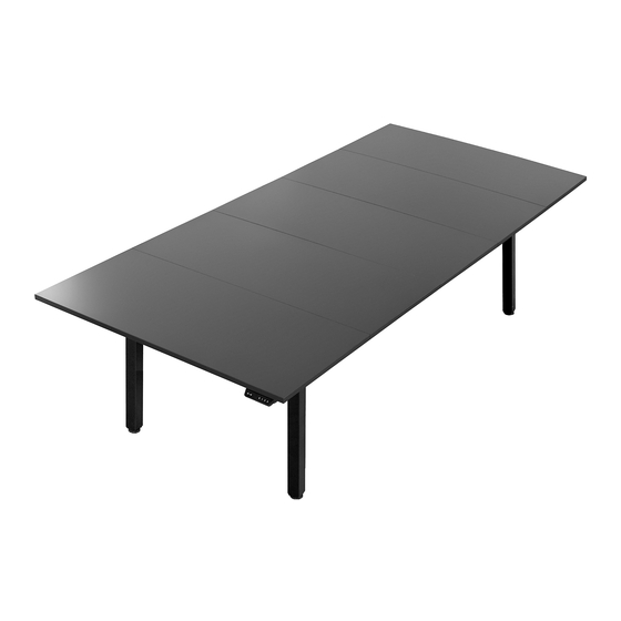
Electric 4-Leg Dual Motor Desk
SKUs: DESK-KIT-404B/N, DESK-KIT-405B/N, DESK-E-400B
Instruction Manual
ASSEMBLY VIDEO AVAILABLE:
Follow along step-by-step with our video walk through by scanning
the QR code with your mobile device or by following the product
link: vivo-us.com/products/desk-e-400b
help@vivo-us.com
309-278-5303
www.vivo-us.com
Advertisement

Related Manuals for Vivo DESK-KIT-404B/N


Summary of Contents for Vivo DESK-KIT-404B/N
- Page 1 Electric 4-Leg Dual Motor Desk SKUs: DESK-KIT-404B/N, DESK-KIT-405B/N, DESK-E-400B Instruction Manual ASSEMBLY VIDEO AVAILABLE: Follow along step-by-step with our video walk through by scanning the QR code with your mobile device or by following the product link: vivo-us.com/products/desk-e-400b www.vivo-us.com help@vivo-us.com...
- Page 2 7AM - 7PM Monday-Friday Give us a Call: Chat Us: Email Us: 309-278-5303 www.vivo-us.com help@vivo-us.com We’re Here for You! Our customer-minded support team is here for YOU, Monday-Friday 7am-7pm CST. We offer immediate assistance with rapid response times from customer service agents and product techncians to...
- Page 3 31-42 c. 5 Panel Conference Table DESK-E-400B + DESK-TOP55B-S/N-S (5 pcs) SKU: DESK-KIT-405B/N pg. 43-54 d. 4 Panel Conference Table DESK-E-400B + DESK-TOP55B-S/N-S (4 pcs) SKU: DESK-KIT-404B/N Control Panel Instructions | All Assemblies Operating/Overview pg. 55-56 Troubleshooting pg. 57...
-
Page 4: Electrical Safety Instructions
Returns | Product Didn’t Work Out? We offer a hassle-free 30 day return on all products. Contact customer support at 309-278-5303 or help@vivo-us.com. Please note: For items ordered in error or no longer needed, the return shipping charges will be at the buyer’s expense. -
Page 5: Package Contents
PACKAGE CONTENTS Please consult the parts list below and ensure you have everything you need to assemble your product. If parts are missing or damaged, please contact us. B (x2) C (x2) A (x2) D (x2) E (x2) Inner Short Right Short Left Long Right Short Middle... - Page 6 [ THIS PAGE INTENIONALLY LEFT BLANK ]...
- Page 7 a. Large Frame Assembly | DESK-E-400B for desktops 96” x 36” to 130” x 60” STEP a.1: Forming Leg Assemblies Form two sets of the the following groups using M8x47mm Screws (S-C) and 5mm Allen Wrench (T-C). When finished, you should have four leg assemblies (two motorized assemblies & two non-motorized assemblies): 1.
- Page 8 STEP a.2: Combining Leg Assemblies Join Motorized and Non-Motorized Leg Assemblies together to create two Joined Assemblies by sliding Short Right and Short Left Crossbars (A,C) over Inner Crossbars (B) as shown. Repeat with remaining leg assemblies. You should now have two Joined Assemblies. Motorized Leg Assembly Non-Motorized...
- Page 9 STEP a.3: Installing Sync Rods 1. Loosen the nut on Sync Rod (I). 2. Insert the hex end of Rod into Leg (J) on Joined Assembly. 3. While holding the hex end, pull the larger rod out until the connector engages with Motorized Leg (H).
- Page 10 STEP a.4: Attach Long Middle Crossbar Lay Joined Assemblies on end, as shown below. Attach Long Middle Crossbars (G) to Left and Right Long Crossbars (D,F) using M8x47mm Screws (S-C) and a 5mm Allen Wrench (T-C). Repeat. NOTE: This is showing the largest frame size (for a 130” x 60” desktop). To shorten frame, assemble crossbars using inner holes sets.
- Page 11 STEP a.5: Combine Assemblies Combine Joined Assemblies together by attaching Short Middle Crossbars (E) to Long Middle Crossbars (G) using M8x47mm Screws (S-C) and a 5mm Allen Wrench (T-C). NOTE: This is showing the largest frame size. To shorten frame, assemble crossbars using inner holes sets.
- Page 12 STEP a.6: Secure Crossbars Fully secure Long Middle Crossbars (G) using M8x35mm Screws (S-D) and 5mm Allen Wrench (T-C). S-D (x8) 5mm Allen Wrench M8x35mm Screws...
- Page 13 STEP a.7: Install Rubber Pads Press Rubber Pads (R) into crossbar tabs, as shown below. R (x16) Rubber Pads...
- Page 14 STEP a.8: Install Desktop Flip the desktop and frame and place the frame in the center of the desktop. Mark mounting loca- tions using a pencil and drill 3/8” (10mm) deep pilot holes using a 7/64” (3mm) drill bit. MULTI-PANEL DESKTOPS: If you are creating a desktop using multiple panels, place them as shown.
- Page 15 STEP a.9: Place Desktop on Frame Flip over the frame and place the desktop on the frame to where the pilot holes are aligned with the frame mounting points. MULTI-PANEL DESKTOPS: Join the panel segments together using Connecting Plates (T), ST4.8x15mm Screws (S-E), and a Phillips screwdriver.
- Page 16 STEP a.10: Secure Desktop to Frame Attach the desktop to the frame using ST4.8x15mm Screws (S-E) and a Phillips screwdriver. S-E (x18) ST4.8x15mm Screw...
- Page 17 STEP a.11: Install Control Panel & Power Adapter Mark Adapter Bracket (N) mounting locations using a pencil and drill 3/8” (10mm) deep pilot holes using a 7/64” (3mm) drill bit. Attach Adapter Bracket (N) to desktop using ST4.8x15mm Screws (S-E) and a Phillips screwdriver. Then slide Power Adapter (M) under Bracket.
- Page 18 STEP a.12: Connect Power Cords To power desk frame, begin by connecting the cords from the Motorized Legs (H) to Control Panel (K) using M1 and M2 slots. Extension Cable (L) can be connected to Motorized Legs if extra length is needed to reach Control Panel. Connect cord from Power Adapter (M) to Control Panel (K) and then connect Power Cable (O) to Power Adapter (M).
- Page 19 b. Small Frame Assembly | DESK-E-400B for desktops 60” x 36” to 96” x 36” STEP b.1: Forming Leg Assemblies Form two sets of the the following groups using M8x47mm Screws (S-C) and 5mm Allen Wrench (T-C). When finished, you should have four leg assemblies (two motorized assemblies & two non-motorized assemblies): 1.
- Page 20 STEP b.2: Combining Leg Assemblies Join Motorized and Non-Motorized LegAssemblies together to create two Joined Assemblies by sliding Short Right and Short Left Crossbars (A,C) over Inner Crossbars (B) as shown. Repeat with remaining leg assemblies. You should now have two Joined Assemblies. Motorized Leg Assembly Non-Motorized...
- Page 21 STEP b.3: Installing Sync Rods 1. Loosen the nut on Sync Rod (I). 2. Insert the hex end of Rod into Leg (J) on Joined Assembly. 3. While holding the hex end, pull the larger rod out until the connector engages with Motorized Leg (H).
- Page 22 STEP b.4: Combine Assemblies Combine assemblies together by attaching Long Middle Crossbars (G) to Left and Right Long Crossbars (D,F) using M8x47mm Screws (S-C) and a 5mm Allen Wrench (T-C). NOTE: This is showing the smallest frame size (for a 60” x 30” desktop). To lengthen frame, assemble crossbars using outer holes sets.
- Page 23 STEP b.5: Secure Crossbars Fully secure Long Middle Crossbars (G) using M8x35mm Screws (S-D) and 5mm Allen Wrench (T-C). S-D (x4) 5mm Allen Wrench M8x35mm Screws...
- Page 24 STEP b.6: Install Rubber Pads Press Rubber Pads (R) into crossbar tabs, as shown below. R (x12) Rubber Pads...
- Page 25 STEP b.7: Pre-Drill Holes Flip the desktop and frame and place the frame in the center of the desktop. Mark mounting locations using a pencil and drill 3/8” (10mm) deep pilot holes using a 7/64” (3mm) drill bit. Multi-Panel Desktops If you are creating a desktop using multiple panels, place them as shown.
- Page 26 STEP b.8: Place Desktop on Frame Flip over the frame and place the desktop on the frame to where the pilot holes are aligned with the frame mounting points. Multi-Panel Desktops Join the panel segments together using Connecting Plates (T), ST4.8x15mm Screws (S-E), and a Phillips screwdriver.
- Page 27 STEP b.9: Secure Frame to Desktop Attach the desktop to the frame using ST4.8x15mm Screws (S-E) and a Phillips screwdriver. S-E (x12) ST4.8x15mm Screws...
- Page 28 STEP b.10: Install Power Adapter & Control Panel Mark Adapter Bracket (N) mounting locations using a pencil and drill 3/8” (10mm) deep pilot holes using a 7/64” (3mm) drill bit. Attach Adapter Bracket (N) to desktop using ST4.8x15mm Screws (S-E) and a Phillips screwdriver. Then slide Power Adapter (M) under Bracket.
- Page 29 STEP b.11: Connect Power To power desk frame, begin by connecting the cords from the Motorized Legs (H) to Control Panel (K) using M1 and M2 slots. Extension Cable (L) can be connected to Motorized Legs if extra length is needed to reach Control Panel. Connect cord from Power Adapter (M) to Control Panel (K) and then connect Power Cable (O) to Power Adapter (M).
- Page 30 [ THIS PAGE INTENIONALLY LEFT BLANK ]...
- Page 31 c. 5 Panel Conference Table Kit | DESK-KIT-405B/N DESK-E-400B + DESK-TOP55B-S (5 pcs) STEP c.1: Forming Leg Assemblies Form two sets of the the following groups using M8x47mm Screws (S-C) and 5mm Allen Wrench (T-C). When finished, you should have four leg assemblies (two motorized assemblies & two non-motorized assemblies): 1.
- Page 32 STEP c.2: Combining Leg Assemblies Join Motorized and Non-Motorized LegAssemblies together to create two Joined Assemblies by sliding Short Right and Short Left Crossbars (A,C) over Inner Crossbars (B) as shown. Repeat with remaining leg assemblies. You should now have two Joined Assemblies. NOTE: The inner crossbars will Motorized Leg remain loose until the frame is...
- Page 33 STEP c.3: Installing Sync Rods 1. Loosen the nut on Sync Rod (I). 2. Insert the hex end of Rod into Leg (J) on Joined Assembly. 3. While holding the hex end, pull the larger rod out until the connector engages with Motorized Leg (H).
- Page 34 STEP c.4: Attach Long Middle Crossbar Lay Joined Assemblies on end, as shown below. Attach Long Middle Crossbars (G) to Left and Right Long Crossbars (D,F) using M8x47mm Screws (S-C) and a 5mm Allen Wrench (T-C). Repeat. NOTE: This is showing the largest frame size (for a 130” x 60” desktop). To shorten frame, assemble crossbars using inner holes sets.
- Page 35 STEP c.5: Combine Assemblies Combine assemblies together by attaching Short Middle Crossbars (E) to Long Middle Crossbars (G) using M8x47mm Screws (S-C) and a 5mm Allen Wrench (T-C). E (x2) S-C (x8) 5mm Allen Wrench Short Middle Crossbars M8x47mm Screws...
- Page 36 STEP c.6: Secure Crossbars Fully secure Long Middle Crossbars (G) using M8x35mm Screws (S-D) and 5mm Allen Wrench (T-C). S-D (x8) 5mm Allen Wrench M8x35mm Screws...
- Page 37 STEP c.7: Install Rubber Pads Press Rubber Pads (R) into crossbar tabs, as shown below. R (x16) Rubber Pads...
- Page 38 STEP c.8: Pre-Drill Pilot Holes Layout all 5 desktop panels bottom side up. Flip the frame and place towards the center of the desktop. Layout Connecting Plates (T) as shown. Mark the frame and connecting plate mounting locations using a pencil and drill 3/8” (10mm) deep pilot holes using a 7/64” (3mm) drill bit. T (x12) Connecting Plates...
- Page 39 STEP c.9: Join Desktop Panels Flip over the frame and place the desktop panels on the frame to where the pilot holes are aligned with the frame mounting points. Join the panel segments together using Connecting Plates (T), ST4.8x15mm Screws (S-E), and a Phillips screwdriver.
- Page 40 STEP c.10: Secure Desktop to Frame Attach the desktop to the frame using ST4.8x15mm Screws (S-E) and a Phillips screwdriver. S-E (x16) ST4.8x15mm Screw...
- Page 41 STEP c.11: Join Desktop Panels Mark Adapter Bracket (N) mounting locations using a pencil and drill 3/8” (10mm) deep pilot holes using a 7/64” (3mm) drill bit. Attach Adapter Bracket (N) to desktop using ST4.8x15mm Screws (S-E) and a Phillips screwdriver. Then slide Power Adapter (M) under Bracket.
- Page 42 STEP c.12: Connect Power To power desk frame, begin by connecting the cords from the Motorized Legs (H) to Control Panel (K) using M1 and M2 slots. Extension Cable (L) can be connected to Motorized Legs if extra length is needed to reach Control Panel. Connect cord from Power Adapter (M) to Control Panel (K) and then connect Power Cable (O) to Power Adapter (M).
- Page 43 4 Panel Conference Table Kit | DESK-KIT-404B/N DESK-E-400B + DESK-TOP55B-S (4 pcs) STEP 1: Forming Leg Assemblies Form two sets of the the following groups using M8x47mm Screws (S-C) and 5mm Allen Wrench (T-C). When finished, you should have four leg assemblies (two motorized assemblies & two non-motorized assemblies): 1.
- Page 44 STEP d.2: Combining Leg Assemblies Join Motorized and Non-Motorized Leg Assemblies together to create two Joined Assemblies by sliding Short Right and Short Left Crossbars (A,C) over Inner Crossbars (B) as shown. Repeat with remaining leg assemblies. You should now have two Joined Assemblies. Motorized Leg Assembly Non-Motorized...
- Page 45 STEP d.3: Installing Sync Rods 1. Loosen the nut on Sync Rod (I). 2. Insert the hex end of Rod into Leg (J) on Joined Assembly. 3. While holding the hex end, pull the larger rod out until the connector engages with Motorized Leg (H).
- Page 46 STEP d.4: Attach Long Crossbars Prop the Joined Assemblies up as shown and attach Long Middle Crossbars (G) to Left and Right Long Crossbars (D,F) as shown and fasten using M8x47mm Screws (S-C) and a 5mm Allen Wrench (T-C). Repeat. G (x2) S-C (x8) 5mm Allen Wrench...
- Page 47 STEP d.5: Combine Assemblies Combine assemblies together by attaching Short Middle Crossbars (E) to Long Middle Crossbars (G) using M8x47mm Screws (S-C) and a 5mm Allen Wrench (T-C). E (x2) S-C (x8) 5mm Allen Wrench Short Middle Crossbar M8x47mm Screws...
- Page 48 STEP d.6: Secure Crossbars Fully secure Long Middle Crossbars (G) using M8x35mm Screws (S-D) and 5mm Allen Wrench (T-C). S-D (x4) M8x35mm Screws 5mm Allen Wrench...
- Page 49 STEP d.7: Install Rubber Pads Press Rubber Pads (R) into crossbar tabs, as shown below. R (x12) Rubber Pads...
- Page 50 STEP d.8: Pre-Drill Pilot Holes Place 4 desktop panels bottom side up. Flip the frame and place towards the center of the desktop. Layout Connecting Plates (T) as shown. Mark the frame and connecting plate mounting locations using a pencil and drill 3/8” (10mm) deep pilot holes using a 7/64” (3mm) drill bit. T (x9) Connecting Plates...
- Page 51 STEP d.9: Connect Desktop Panels Flip over the frame and place the desktop panels on the frame to where the pilot holes are aligned with the frame mounting points. Join the panel segments together using Connecting Plates (T), ST4.8x15mm Screws (S-E), and a Phillips screwdriver.
- Page 52 STEP d.10: Connect Desktop to Frame Attach the desktop to the frame using ST4.8x15mm Screws (S-E) and a Phillips screwdriver. S-E (x12) ST4.8x15mm Screw...
- Page 53 STEP d.11: Install Control Panel & Power Adapter Mark Adapter Bracket (N) mounting locations using a pencil and drill 3/8” (10mm) deep pilot holes using a 7/64” (3mm) drill bit. Attach Adapter Bracket (N) to desktop using ST4.8x15mm Screws (S-E) and a Phillips screwdriver. Then slide Power Adapter (M) under Bracket.
- Page 54 STEP d.12: Connect Power Cords To power desk frame, begin by connecting the cords from the Motorized Legs (H) to Control Panel (K) using M1 and M2 slots. Extension Cable (L) can be connected to Motorized Legs if extra length is needed to reach Control Panel. Connect cord from Power Adapter (M) to Control Panel (K) and then connect Power Cable (O) to Power Adapter (M).
-
Page 55: Operating Control Panel
CONTROL PANEL UP ARROW: Short press to lift desk .39” (1cm). Long press for continuously lift. Release when at desired height. DOWN ARROW: Short press to lower desk .39” (1cm). Long press to continuously lower. Release when at desired height. SAVE: Raise or lower desk frame to desired height. - Page 56 Power-Saving Mode When no actions are made for over 1 minute, the system will enter power-saving mode, touch any button to enter operation mode. Switch the Displayed Unit of Measurement The preset measurement shown on the display is cm. If you would like to change cm to inch, long press the "S"...
- Page 57 If not, perform Reset Process and power on again. Undervoltage Error: Unplug desk for 30-60 seconds, then plug it back in. If error does not clear, please contact product support at 309-278-5303 or help@vivo-us.com.
- Page 58 WHO WE ARE VIVO is more than a brand of ergonomic office furniture. We are a team of creative and innovative indivuduals working together to offer high quality, affordable ergonomic solutions. We think and work outside of the box to serve...
-
Page 59: Need Assistance
Call Us: 309-278-5303 Average Resolution Time: 5m 4s Chat Us: www.vivo-us.com Average Resolution Time: < 15m Email Us: help@vivo-us.com Average Resolution Time: 1HR 8M 23% within < 15m 38% within <... - Page 60 LOVE YOUR NEW VIVO SETUP? Ready to share that new amazing setup? Want to brag about that amazing new ergonomic solution? Tag us in your photo! VIVO-us @vivo_us FOR MORE GREAT VIVO PRODUCTS, CHECK OUT OUR WEBSITE AT: WWW.VIVO-US.COM LAST UPDATED: 07/07/2023 REV2LF...
Need help?
Do you have a question about the DESK-KIT-404B/N and is the answer not in the manual?
Questions and answers