Grandstream Networks GWN76 Series User Manual
Wi-fi access point
Hide thumbs
Also See for GWN76 Series:
- User manual (144 pages) ,
- Master/slave architecture manual (15 pages) ,
- User manual (140 pages)
Table of Contents
Advertisement
Quick Links
Advertisement
Table of Contents

Related Manuals for Grandstream Networks GWN76 Series


Summary of Contents for Grandstream Networks GWN76 Series
- Page 1 Grandstream Networks, Inc. Wi-Fi Access Points GWN76xx – User Manual...
-
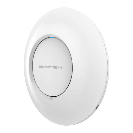
Page 2: Product Overview
WELCOME Grandstream’s powerful indoor and outdoor Wi-Fi Access Points offer high-performance networking and an exceptional Wi-Fi coverage range The outdoor series offer weatherproof certified casing and supports up to a 750-meter coverage range. They are supported by GWN.Cloud and GWN Manager, Grandstream’s cloud and on-premise free management platforms. Each device also includes an embedded controller within the product’s web user interface for easy administration of locally deployed Wi-Fi APs. - Page 3 device 2×2:2 2.4GHz (MU-MIMO) MIMO 4×4:4 5GHz (MU-MIMO) Up to 175 meters Coverage Range *coverage range can vary based on the environment 5G: 25dBm Maximum TX Power 2.4G: 27dBm *Maximum power varies by country, frequency band, and MCS rate 2.4GHz 802.11b: -96dBm@1Mbps, -88dBm@11Mbps;...
- Page 4 Package Content GWN7664LR 802.11ax Wireless AP, Mounting Kits, Quick Installation Guide Compliance FCC, CE, RCM, IC, UKCA GWN7662 Technical Specifications GWN7624 Technical Specifications Wi-Fi Standards IEEE 802.11 a/b/g/n/ac Internal Antennas: 2x 5GHz + 2x (5GHz & 2.4GHz) Antennas 2.4GHz, gain 3dBi; 5GHz, gain 5dBi 2.4GHz: IEEE 802.11n: 6.5Mbps to 300Mbps...
- Page 5 Concurrent Clients Up to 200 1x 10/100/1000M uplink Ethernet port with PoE/PoE+ Network Interfaces 2x 10/100/1000M Ethernet port with PSE 1x 10/100/1000M Ethernet port Auxiliary Ports 1x Reset Pinhole Mounting In-wall mountable LEDs 1 tri-color LEDs for device tracking and status indication Network Protocols IPv4, IPv6, 802.1Q, 802.1p, 802.1x, 802.11e/WMM 802.11e/WMM, VLAN, TOS...
- Page 6 IEEE 802.11a: 6, 9, 12, 18, 24, 36, 48, 54 Mbps *Actual throughput may vary depending on many factors including environmental conditions, distance between devices, radio interference in the operating environment and mix of devices in the network 2.4GHz Radio: 2412 - 2484 MHz Frequency Bands 5GHz Radio: 5180 - 5825 MHz *Not all frequency bands can be used in all regions...
- Page 7 Auto Power Saving Self-power adaptation upon auto detection of PoE or PoE+ Power and Green PoE 802.3af/ 802.3at; Energy Efficiency Maximum Power Consumption: 18W Operation:-30°Cto 60°C Environmental Storage: -30°C to 60°C Humidity: 10% to 90% Non-condensing Unit Dimension: 562.3mm(L)x140mm(W)x44.9mm(H); Physical Unit + Mounting Kits Dimension: 562.3mm(L)x140mm(W)x66.9mm(H);...
- Page 8 2.4GHz 802.11b: -96dBm@1Mbps, -88dBm@11Mbps; 802.11g: -93dBm @6Mbps, -75dBm@54Mbps; 802.11n 20MHz: -73dBm @MCS7; 802.11n 40MHz:-70dBm @MCS7 Receiver Sensitivity 5GHz 802.11a: -92dBm @6Mbps, -74dBm @54Mbps; 802.11n 20MHz: -74dBm @MCS7; 802.11n 40MHz:-71dBm @MCS7 802.11ac 20MHz: -67dBm@MCS8; 802.11ac: HT40:- 63dBm @MCS9; 802.11ac 80MHz: -59dBm @MCS9 SSIDs 16 SSIDs total, 8 per radio (2.4GHz &...
- Page 9 IEEE 802.11ax: 8 Mbps to 2402 Mbps IEEE 802.11ac: 6.5 Mbps to 1733 Mbps IEEE 802.11n: 6.5 Mbps to 600 Mbps IEEE 802.11a: 6, 9, 12, 18, 24, 36, 48, 54 Mbps 2.4G: Wi-Fi Data Rates IEEE 802.11ax: 8 Mbps to 1147 Mbps IEEE 802.11n: 6.5 Mbps to 600Mbps IEEE 802.11b: 1, 2, 5.5, 11Mbps IEEE 802.11g: 6, 9, 12, 18, 24, 36, 48, 54 Mbps...
-
Page 10: Network Management
2.4G 802.11b: -99dBm@1Mbps, -91dBm@11Mbps; 802.11g: -94dBm @6Mbps, -78dBm@54Mbps; 802.11n 20MHz: -75dBm @MCS7; 802.11n 40MHz:-71dBm @MCS7; 802.11ax 20MHz: -64dBm @ MCS11; 802.11ax 40MHz: -63dBm @MCS11 Receiver Sensitivity 802.11a: -95dBm @6Mbps, -77dBm @54Mbps; 802.11n 20MHz: -74dBm @MCS7; 802.11n 40MHz:-71dBm @MCS7 802.11ac 20MHz: -70dBm@MCS8; 802.11ac: HT40:- 66dBm @MCS9; 802.11ac 80MHz: -62dBm @MCS9;... - Page 11 Package Content GWN7664 802.11ax Wireless AP, Mounting Kits, Quick Start Guide Compliance FCC, CE, RCM, IC GWN7664 Technical Specifications GWN7660 Technical Specifications Wi-Fi Standards IEEE 802.11 a/b/g/n/ac/ax. 2 dual band internal antennas Antennas 2.4GHz, gain 3dBi / 5 GHz, gain 4dBi IEEE 802.11ax: 7.3 Mbps to 1201 Mbps IEEE 802.11ac: 6.5 Mbps to 867 Mbps IEEE 802.11n: 6.5Mbps to 300Mbps...
- Page 12 2.4G: 24 dBm Maximum TX Power 5G: 22 dBm *Maximum power varies by country, frequency band and MCS rate 2.4G 802.11b: -96dBm@1Mbps, -88dBm@11Mbps; 802.11g: -93dBm @6Mbps, -75dBm@54Mbps; 802.11n 20MHz: -73dBm @MCS7; 802.11n 40MHz:-70dBm @MCS7; 802.11ax 20MHz: -60dBm @ MCS11; 802.11ax 40MHz: -58dBm @MCS11 Receiver Sensitivity 802.11a: -92dBm @6Mbps, -74dBm @54Mbps;...
- Page 13 Unit Dimension: 180.4mm x 180.4mm x 40.8mm; Unit Weight: 443g Physical Entire Package Dimension: 228.5x220x79mm; Entire Package Weight: 774g Package Content GWN7660 802.11ax Wireless AP, Mounting Kits, Quick Start Guide Compliance FCC, CE, RCM, IC GWN7660 Technical Specifications GWN7660LR Technical Specifications Wi-Fi Standards IEEE 802.11 a/b/g/n/ac/ax 2 dual band external antennas...
- Page 14 2.4G 802.11b: -99dBm@1Mbps, -90dBm@11Mbps; 802.11g: -93dBm @6Mbps, -77dBm@54Mbps; 802.11n 20MHz: -74dBm @MCS7; 802.11n 40MHz:-72dBm @MCS7; 802.11ax 20MHz: -64dBm @ MCS11; 802.11ax 40MHz: -62dBm @MCS11 Receiver Sensitivity 802.11a: -95dBm @6Mbps, -77dBm @54Mbps; 802.11ac 20MHz: -71dBm@MCS8; 802.11ac: HT40:- 67dBm @MCS9; 802.11ac 80MHz: -64dBm @ MCS9;...
- Page 15 Wi-Fi Standards IEEE 802.11 a/b/g/n/ac (Wave-2). 4x 2.4 GHz, gain 4dBi, internal antenna Antennas 4x 5 GHz, gain 5dBi, internal antenna IEEE 802.11ac: 6.5 Mbps to 1733Mbps IEEE 802.11a: 6, 9, 12, 18, 24, 36, 48, 54 Mbps IEEE 802.11n: 6.5Mbps to 600Mbps IEEE 802.11b: 1, 2, 5.5, 11Mbps Wi-Fi Data Rates IEEE 802.11g: 6, 9, 12, 18, 24, 36, 48, 54 Mbps...
-
Page 16: Auxiliary Ports
SSIDs 32 SSIDs total, 16 per radio (2.4GHz and 5GHz) Concurrent Clients 200+ Network Interfaces 2x autosensing 10/100/1000 Base-T Ethernet Ports Auxiliary Ports 1x Reset Pinhole, 1x Kensington lock Mounting Indoor wall mount or ceiling mount, kits included LEDs 3 tri-color LEDs for device tracking and status indication Network Protocols IPv4, 802.1Q, 802.1p, 802.1x, 802.11e/WMM, 802.11h 802.11e/WMM, VLAN, TOS... - Page 17 IEEE 802.11ac: 6.5 Mbps to 1300Mbps IEEE 802.11a: 6, 9, 12, 18, 24, 36, 48, 54 Mbps IEEE 802.11n: 6.5 Mbps to 450 Mbps IEEE 802.11b: 1, 2, 5.5, 11Mbps Wi-Fi Data Rates IEEE 802.11g: 6, 9, 12, 18, 24, 36, 48, 54 Mbps *Actual throughput may vary depending on many factors including environmental conditions, distance between devices, radio interference in the operating environment and mix of devices in the network...
- Page 18 LEDs 1× tri-color LED for device tracking and status indication Network Protocols IPv4, 802.1Q, 802.1p, 802.1x, 802.11e/WMM, 802.11h 802.11e/WMM, VLAN, TOS ≤ 50 APs: Light-weight Master in AP Network ≤ 3000 APs: On-Premises controller Management ≤ +∞ APs: Cloud management POE 802.3af/ 802.3at;...
- Page 19 WEP, WPA3, WPA/WPA2-PSK, WPA/WPA2-Enterprise (TKIP/AES), anti-hacking secure boot and Wi-Fi and System critical data/control lockdown via digital signatures, unique security certificate and random default Security password per device 3×3:3 2.4GHz, MIMO 3×3:3 5GHz 575ft. (175 meters) Coverage Range *coverage range can vary based on environment 5G: 26dBm (FCC) / 20dBm (CE) Maximum TX Power 2.4G: 26dBm (FCC) / 17dBm (CE)
- Page 20 Operation: 0°C to 50°C Environmental Storage: -10°C to 60°C Humidity: 10% to 90% Non-condensing Unit Dimension: 205.3 x 205.3 x 45.9mm; Unit Weight: 540g Physical Unit + Mounting Kits Dimension: 205.3 x 205.3 x 50.9mm; Unit + Mounting Kits Weight: 600g Entire Package Dimension: 258 x 247 x 86mm;...
- Page 21 Up to 165 meters Coverage Range *coverage range can vary based on environment 5G: 24dBm Maximum TX Power 2.4G: 22dBm *Maximum power varies by country, frequency band and MCS rate 2.4G 802.11b: -96dBm@1Mbps, -88dBm@11Mbps; 802.11g: -93dBm @6Mbps, -75dBm@54Mbps; 802.11n 20MHz: -73dBm @MCS7; 802.11n 40MHz:-70dBm @MCS7 Receiver Sensitivity 802.11a: -92dBm @6Mbps, -74dBm @54Mbps;...
- Page 22 Unit Dimension: 180.4mmx180.4mmx40.8mm; Unit Weight: 388.2g Physical Entire Package Dimension: 228.5x220x79mm; Entire Package Weight: 719.3g Package Content GWN7610 802.11ac Wireless AP, Mounting Kits, Quick Start Guide Compliance FCC, CE, RCM, IC GWN7605 Technical Specifications GWN7605LR Technical Specifications Wi-Fi Standards IEEE 802.11a/b/g/n/ac (Wave-2) 2 dual band external antennas Antennas 2.4GHz, gain 3.5dBi...
- Page 23 2.4G 802.11b: -96dBm@1Mbps, -88dBm@11Mbps; 802.11g: -93dBm @6Mbps, -75dBm@54Mbps; 802.11n 20MHz: -73dBm @MCS7; 802.11n 40MHz:-70dBm @MCS7 Receiver Sensitivity 802.11a: -92dBm @6Mbps, -74dBm @54Mbps; 802.11ac 20MHz: -67dBm@MCS8; 802.11ac: HT40:- 63dBm @MCS9; 802.11ac 80MHz: -59dBm @MCS9 16 SSIDs total, 8 per radio (2.4GHz and 5GHz) SSIDs *GWN7605LR when deployed as Master can only be added to 8 SSIDs.
- Page 24 Antennas 2x 2.4 GHz, gain 3 dBi, internal antenna, 2x 5 GHz, gain 3 dBi, internal antenna IEEE 802.11ac: 6.5 Mbps to 877 Mbps IEEE 802.11a: 6, 9, 12, 18, 24, 36, 48, 54 Mbps IEEE 802.11n: 6.5 Mbps to 300 Mbps; 400 Mbps with 256-QAM on 2.4GHz IEEE 802.11b: 1, 2, 5.5, 11 Mbps Wi-Fi Data Rates IEEE 802.11g: 6, 9, 12, 18, 24, 36, 48, 54 Mbps...
- Page 25 Network Protocols IPv4, 802.1Q, 802.1p, 802.1x, 802.11e/WMM, 802.11h 802.11e/WMM, VLAN, TOS Embedded controller in GWN7600 allows it to auto-discover, auto-provision and manage up to 30 Network GWN76XX in a network Management GWN.Cloud offers a free cloud management platform for unlimited GWN APs DC Input: 24VDC/1A Power and Green Power over Ethernet (802.3af) compliant...
- Page 26 2.4G: 20 and 40 MHz Channel Bandwidth 5G: 20,40 and 80 MHz WEP, WPA3, WPA/WPA2-PSK, WPA/WPA2 Enterprise (TKIP/AES), anti-hacking secure boot and Wi-Fi and System critical data/control lockdown via digital signatures, unique security certificate and random default Security password per device MIMO 2×2:2 2.4GHz (MIMO), 2×2:2 5GHz (MU-MIMO) Up to 984ft.
- Page 27 Operation: -30°C to 60°C Temperature Storage: -30°C to 70°C & Humidity Humidity: 5% to 95% Non-condensing Unit Dimension: 290×150×35mm; Unit Weight: 708g Unit + Mounting Kits Dimension: 290×150×56mm; Physical Unit + Mounting Kits Weight: 1528.2g Entire Package Dimension: 423×187×97mm; Entire Package Weight: 1844g Enterprise 802.11ac Wave-2 Outdoor Long Range Wi-Fi Access Point, Mounting Kits, Quick Package Content Installation Guide...
- Page 28 4×4:4 2.4G (MIMO), MIMO 4×4:4 5G (MU-MIMO) Up to 984ft. (300 meters) Coverage Range *Coverage range can vary based on environment 2.4G: 27 dBm Maximum TX Power 5G: 25 dBm *Maximum power varies by country, frequency band and MCS rate 2.4G 802.11b: -96dBm@1Mbps, -88dBm@11Mbps;...
- Page 29 Package Content GWN7630LR 802.11ac Wireless AP, Mounting Kits, Quick Installation Guide Waterproof Grade IP66-level weatherproof capability when installed vertically Compliance FCC, CE, RCM, IC GWN7630LR Technical Specifications GWN7602 Technical Specifications Wi-Fi Standards IEEE 802.11 a/b/g/n/ac 2 Dual band internal antennas Antennas Antenna 1 - 2.4GHz: gain 3.0dBi, 5GHz: gain 3.5dBi Antenna 2 - 2.4GHz: gain 3.5dBi, 5GHz: gain 3.0dBi...
-
Page 30: Installation
SSIDs 8 SSIDs total, 5 per radio (2.4GHz & 5GHz) Concurrent Clients Up to 80 1x 10/100/1000M uplink Ethernet port with PoE/PoE+ Network Interfaces 2x 10/100M Ethernet port with PSE 1x 10/100M Ethernet port Auxiliary Ports 1x Reset Pinhole Mounting Wall mountable LEDs 1 tri-color LEDs for device tracking and status indication... - Page 31 Ceiling Mounting Bracket Plastic Expansion Bolt M3 NUT Screw (PM 3 x 50) Screw (PM 3.5 x 20) Quick Installation Guide GWN76xx Equipment Packaging GWN76xx Equipment Packaging Below is the equipment packaging for GWN7600LR model. Main Case Yes (1) Cover Interface Yes (1) Base Bracket Yes (1)
- Page 32 GWN7600LR Equipment Packaging GWN7600LR Equipment Package Below is the equipment packaging for GWN7630LR, GWN7605LR, GWN7660LR and GWN7664LR models. Main Case Yes (1) GWN7630LR: Yes (4) Antenna GWN7605LR: Yes (2) GWN7660LR: Yes (2) GWN7664LR: Yes (4) Base Bracket Yes (1) Screw (PM 3.0×7) Yes (4) Expansion Screw Yes (4)
-
Page 33: Gwn76Xx Access Point Ports
Main Case Yes (1) Screw PM 2.5*6*4 mm Yes (2) Screw KB 2.6*6 Yes (1) Screw KB 3.5*26 Yes (4) Quick Installation Guide Yes (1) GWN7624 Equipment Packaging GWN7624 Equipment Package The equipment packaging for GWN7602 model. Main Case Yes (1) PA3.5*20 Screws Yes (2) Anchors Screws... - Page 34 GWN76xx Ports GWN7610/GWN7600 Ports GWN7600LR Ports GWN7630LR /GWN7605LR/GWN7660LR/GWN7664LR Ports...
-
Page 35: Power And Connect Gwn76Xx Access Point
GWN7624 Ports GWN7602 Ports Port Description Power adapter connector (12V, 2A) for GWN7610 Power Power adapter connector (24V, 1A) for GWN7600 and GWN7602 Ethernet RJ45 port (10/100/1000Mbps) supporting PoE/PoE+. * GWN7600 supports PoE (802.3af) only NET/PoE * GWN7624 supports 2x 10/100/1000Mbps Ethernet ports with PSE. •... -
Page 36: Wall Mount
Connect the other end of the Ethernet cable(s) into a LAN port to your Network. (Use PoE/PoE+ switch for GWN76XX). Step 3: For GWN7610/GWN7600 and GWN7602, connect the 24V DC power adapter into the power jack on the back of the access point. -
Page 37: Ceiling Mount
Wall Mount – Steps 1 & 2 Step 2: Use a pencil to mark the four mounting holes (screw holes DIA 5.5mm, reticle hole DIA 25mm). Step 3: Insert screw anchors into the 5.5 mm holes. Attach the mounting bracket to the wall by inserting the screws into the anchors. Wall Mount –... - Page 38 Remove the ceiling tile. Ceiling Mount – Steps 1 & 2 Step 2: Place the ceiling backing plate in the center of the ceiling tile and mark the mounting screw holes (screw holes DIA 5.5mm, reticle hole DIA 25mm). Step 3: Insert the screws through the mounting bracket.
-
Page 39: Mounting Instructions For Gwn7600Lr
Ceiling Mount – Steps 5 & 6 Step 6: Turn the GWN clockwise until it locks into place and fits the locking tab. Note Ceiling mounting is recommended for optimal coverage performance. Mounting Instructions for GWN7600LR Please refer to the following steps for the mounting your GWN7600LR correctly. 1. - Page 40 GWN7600LR Horizontal Mounting Mounting Instructions for GWN7630LR/GWN7605LR/GWN7660LR/GWN7664LR GWN76xxLR can be mounted on the wall or on a metal bar. Please refer to the following steps for the appropriate installation. GWN7630LR/GWN7605LR/GWN7660LR /GWN7664LR Mounting Instructions 1. Connect the Ethernet cable (RJ45) to the correct port of your GWN7630LR/GWN7605LR/GWN7660LR/GWN7664LR and insert the cover bracket.
-
Page 41: Pole Mount
2. Attach the GWN7630LR/GWN7605LR/GWN7660LR/GWN7664LR access point by securing the Base Bracket with the expansion screws on the wall. Pole Mount GWN7630LR/GWN7605LR/GWN7660LR /GWN7664LR Pole Mount 1. Open the metal straps by turning the locking mechanism counter-clockwise. You can loosen it by hand or use a flathead screwdriver. -
Page 42: Getting Started
GWN7624 Wall Installation Mounting Instructions for GWN7602 GWN7602 can be mounted on the wall, Please refer to the following steps for the appropriate installation. Wall Mount (GWN7602) 1. Use a measuring tape to measure the distance between the two wall mount slots on the back of the GWN7602 access point and use a pencil to mark the mounting screw holes on the wall. -
Page 43: Discover The Gwn76Xx
Blinking green Firmware update in progress Solid green Firmware update successful Blinking red Delete paired slave – Factory reset initiated Solid red Firmware update failed Solid purple Unit not provisioned Blinking blue Unit provisioning in progress Solid blue Unit is provisioned successfully Blinking White Used for Access Point location feature Solid Yellow... -
Page 44: Access Web Gui
3. The tool will discover all GWN76XX Access Points connected on the network showing their MAC, IP addresses and firmware version. 4. Click on Manage Device to be redirected directly to the GWN76XX’s configuration interface, or type in manually the displayed IP address on your browser. -
Page 45: Web Gui Languages
GWN AP’s web UI access will be locked for 15 mins after 5 login failures Note: GWN7602 doesn’t support embedded Web server, it can only be managed through another GWN access point as a slave, GWN Cloud or GWN Manager. WEB GUI Languages Currently the GWN76XX series web GUI supports 17 languages including English, Chinese, Spanish etc. -
Page 46: Save And Apply Changes
New Firmware Notification: Starting from firmware version 1.0.5.13/1.0.5.14, and once a different OFFICIAL firmware is released on Grandstream Networks website, the master AP will popup reminder notification to the administrator in order to upgrade the device. You can click on button in order to be redirected to the release note of the new firmware version, for upgrading steps please refer to section [UPGRADING AND PROVISIONING]. - Page 47 Apply Changes GWN MANAGEMENT PLATFORMS GWN.Cloud Starting from firmware 1.0.6.41/1.0.6.43, the GWN76XX can be managed by your GWN.Cloud account, GWN.Cloud web interface now can be accessed at https://www.gwn.cloud. GWN.Cloud Architecture GWN Manager Starting from firmware 1.0.13.1, the GWN76XX can be managed and monitored by your GWN Manager account, GWN Manager On-premises Access Points Controller platform can be installed using the link below: https://www.grandstream.com/support/firmware GWN Manager Architecture...
-
Page 48: Using Gwn76Xx As Standalone Access Point
USING GWN76XX AS STANDALONE ACCESS POINT The GWN76XX can be used in Standalone mode, where it can act as Master Access Point Controller or in Slave mode and managed by another GWN76XX Master. This section will describe how to use and configure the GWN76XX in standalone mode. Connect to GWN76XX Default Wi-Fi Network GWN76XX can be used as standalone access point out of box, or after factory reset with Wi-Fi enabled by default. -
Page 49: Login Page
Login Page After login, users can use the Setup Wizard tool to go through the configuration setup or exit and configure it manually. Setup Wizard can be accessed anytime by clicking on while on the web interface. Setup Wizard Discover and Pair Other GWN76xx Access Point First, note that by default the GWN controller access point will automatically discover all APs connected to the same LAN (broadcast domain), there is also a possibility to pair and provision remote APs using DHCP option 43 with master direction explained below. -
Page 50: Transfer Ap - Transfer Network Group
To Pair a GWN76XX access point connected to the same Network as the GWN76xx follows the below steps: 1. Connect to the GWN76xx Web GUI as Master and go to Access Points → Configuration. Discover and Pair GWN76XX 2. Click on to discover access points within GWN76xx Network, the following page will appear. -
Page 51: Failover Master
Navigate to AP Web UI → Access Points → Configuration page, please refer to the figure below: Access points configuration page Then select where to transfer the select AP, either GWN Cloud or GWN Manager. Transfer AP After this step, you will be redirected to GWN Cloud/GWN Manager page, select the network and click on “Save” button to complete the transfer. -
Page 52: Failover Mode
Failover Master Users could select the Failover Master by following below steps: Log into Web GUI of the Master access point then navigate to Access points → Configuration then click on finally select the candidate access point from the drop-down list to be used as a Failover AP. Failover AP Failover Mode Once Failover slave has been selected, the primary master will send the configuration of the network to the Failover slave and... -
Page 53: Takeover Feature
Failover Mode GUI The Failover mode has only read permission on the configuration and limited options, users still can reboot other slave Access points in case it is needed. Users also can press on « Switch to Master » button in order to set the Failover slave as the new primary master of the wireless network, once this is done they have full write permission control over the web GUI option as usual. -
Page 54: Transfer To Master
Takeover – Step 3 Transfer to Master From the Master Access Point, the Administrator do have the capability to assign any Slave Access point to become the new Master to manage all the already paired Access points. Except for GWN7602. Navigate to Web UI →... -
Page 55: Client Bridge
Client Bridge The Client Bridge feature allows an access point to be configured as a client for bridging wired only clients wirelessly to the network. When an access point is configured in this way, it will share the Wi-Fi connection to the LAN ports transparently. This is not to be confused with a mesh setup. - Page 56 GWN7624 slave login page Notes: If the AP is slave to a Master controller, the default username is admin, and the default password is the master AP’s password. If the AP is paired to the GWN.Cloud the default username is admin, and the default password is the SSH Password (GWN.Cloud →...
-
Page 57: Manager Settings
Manager Settings The Master (Manager Address) and Port can be found here to GWN7624 be discovered by the Manager. Slave AP manager settings Manager Address Enter the IP address of the GWN Manager Manager Port Enter the port set for the GWN Manager Allow DHCP Option 43 This configuration will not be effective if AP has been managed by cloud. - Page 58 Status The Status page lists all the access points assigned to the selected network, along with the possibility to perform some basic operations such locating the device (LEDs start blinking in White) or clear the usage data, also users can check more detailed information about each access point and benefit from useful debugging tools which can help diagnose issue when they appear.
- Page 59 GWN7624 Configuration Page Upgrade Select slave AP(s) to upgrade and press button. Refer to [Upgrading Slave Access Points] for more details. Reboot Select slave AP(s) to reboot and press button. Reboot Slave Select slave AP(s) to reboot and press button. There are two methods to add new access points, either manually from the master AP or using GWN Cloud App.
-
Page 60: Configure Access Points
Delete Access Point Reboot Access Points To reboot an Access point, select it then click on Reboot button, the below confirmation message will be displayed: Reboot Access Point Configure Access Points To configure an access point, select and click on button. - Page 61 5G in Priority: 5G Band will be prioritized over 2G Band Balance: GWN will balance between the clients connected to 2G and those connected to 5G. Use Radio Settings: GWN will use the value configured under Radio page. Configure a schedule for when the Wi-Fi will be ON or Off, by default is disable or the user can Enable Schedule enable it and select a shedule form the drop-down list or use radio settings.
- Page 62 Reset Access Point SSIDs When using GWN76XX as Master Access Point, users can create different SSIDs and assign GWN76XX Slave Access Points to them. Log in as Master to the GWN76XX Web GUI and go to SSIDs. SSIDs All GWN76XX can support up to 32 SSIDs while the GWN7605/GWN7605LR models can support up to 16 SSIDs, and GWN7602 can support up to 8 SSIDs, click on to add a new SSID.
- Page 63 Enter the VLAN ID corresponding to the SSID. This is available when Client IP Assignment is set to VLAN Bridge. Set the security mode for encryption, 8 options are available: • WEP 64-bit: Using a static WEP key. The characters can only be 0-9 or A-F with a length of 10, or printable ASCII characters with a length of 5.
- Page 64 RADIUS Sever Configures RADIUS authentication server address. This field is available only when “WPA Key Address Mode” is set to “802.1x”. Configures RADIUS Server Listening port. Default is: 1812. This field is available only when “WPA RADIUS Server Port Key Mode” is set to “802.1x”. Enter the secret password for client authentication with RADIUS server.
- Page 65 Select to hide SSID. SSID will not be visible when scanning for Wi-Fi, to connect a device to SSID Hidden hidden SSID, users need to specify SSID name and authentication password manually. Configures the frequency of DTIM (Delivery Traffic Indication Message) transmission per each beacon broadcast.
- Page 66 Once enabled, the client Bonjour on the SSID is forwarded to the VLAN of the Bonjour service Enable Bonjour (such as Samba). Supported on GWN7605, GWN7605LR, GWN7615, GWN7630, GWN7630LR, Gateway GWN7660, GWN7660LR Wi-Fi Device Membership: Used to add or remove paired access points to the SSID. The MAX SSID number is separately counted for each band (2.4GHzor 5Ghz).
-
Page 67: Access Control
Users can press button to customize items to display on the page. Following items are supported: Clients – Select Items ACCESS CONTROL Access List From this menu, users can manage in global way the blacklist of clients that will be blocked from accessing the Wi-Fi network, click on to add or remove MAC addresses of client from global blacklist. - Page 68 Adding Client Access List Users can also Import/Export the client access lists in CSV format as shown below: Import/Export the client access Users can check « Enable Schedule » to assign a schedule for the list when it will take effect. Adding New Access List Once this is done, this access list can be used under SSID Wi-Fi settings to filter clients either using whitelist or blacklist mode.
-
Page 69: Time Policy
Time Policy The timed client disconnect feature allows the system administrator to set a fixed time for which clients should be allowed to connect to the access point, after which the client will no longer be allowed to connect for a user configurable cool-down period. - Page 70 Field Description Enabled Enable/Disable the Bandwidth rule. SSID Select which SSID will be affected by the bandwidth rule limitation. Choose the type of rule to be applied on bandwidth utilization from the dropdown list, three options are Range available: Per-SSID: Set a bandwidth limitation on the SSID level. Per-User: Set a bandwidth limitation per Constraint Client.
-
Page 71: Captive Portal
CAPTIVE PORTAL Captive Portal feature on GWN76XX AP helps to define a Landing Page (Web page) that will be displayed on Wi-Fi clients’ browsers when attempting to access Internet. Once connected to a GWN76XX AP, Wi-Fi clients will be forced to view and interact with that landing page before Internet access is granted. -
Page 72: Internal Splash Page
Click on to edit the policy. Click on to delete the policy. Click on to add a policy. The policy configuration page allows adding multiple captive portal policies which will be applied to SSIDs and contains options for different authentication types a splash page that can be easily configured as shown on the next section. Administrator can use an internal or external splash page. - Page 73 Configures the time when the client will automatically deauthenticate when it is idle. This does not apply to Client Idle Timeout Voucher Captive portal mode. Unauthenticated Client Configures a timeout period, after which unauthenticated client devices will be disconnected, and Timeout reconnection is not allowed.
-
Page 74: External Splash Page
X.509 Cert SHA1 enter the X.509 Cert SHA1 Fingerprint Fingerprint If Authentication Type is set to “Active Directory” AD Server URL Specify Active Directory URL Redirect URL Enter the redirect URL X.509 Cert SHA1 enter the X.509 Cert SHA1 Fingerprint Fingerprint For all Authentication Types If checked, the users will be redirected to the default portal page once connected to the GWN.•... -
Page 75: Splash Page
External Splash Page Enter the External Splash Page URL, and make sure to enter the pre-authentication rules request by the external portal platform in the pre-authentication configuration option. RADIUS Server Fill in the IP address of the RADIUS server. Address RADIUS Server Port Set the RADIUS server port, the default value is 1812. -
Page 76: Voucher Feature Description
Captive Portal – Splash Page User can add folder in corresponding folder by selecting the folder and click on Click on to upload a file from local device. Click on to download the files in Captive Portal folder. Click on to edit the corresponding file, in another word, to replace the file with a new one. -
Page 77: Using Voucher With Gwn Captive Portal
The admin can verify the status of each voucher on the list (In use, not used, expired …etc.). Press to print the voucher, to delete it or to renew the voucher. Add Voucher Sample The below figure shows the list of the vouchers after GWN randomly generates the code for each one. Figure 84: Vouchers List Users can click on buttons to delete and print multiple vouchers or click... - Page 78 In order to successfully use the voucher feature, users will need to create a captive portal in order to request voucher authentication codes from users before allowing them access to internet. More details about captive portal will be covered on next section but for voucher configuration please follow below steps.
- Page 79 ● Disable Band steering: This will disable the band steering feature and the access point will accept the band chosen by the client. ● 2G in Priority: 2G Band will be prioritized over the 5G Band.List Item 2 ● 5G in Priority: 5G Band will be prioritized over the 2G BandList Item 3 ●...
- Page 80 Allow Legacy Devices Check to support 802.11b devices to connect the AP in 802.11n/g mode. (2.4GHz setting). (802.11b) Enable Minimum Configures whether to enable/disable Minimum RSSI function. This option can be either Disabled or Enabled RSSI and set manually or set to Use Radio Settings. Specify whether to limit the minimum access rate for clients.
- Page 81 Specify the rogue AP detect range. • Same channel: AP will execute simple detection on the APs around, this mode almost has no effects on the wireless network communication. Detect range • All channels: AP will execute a deep detection every 5 minutes. And the clients connecting to the AP will have few seconds of communication interrupt.
- Page 82 Select type of traffic to be affected by the outbound rule like ICMP, HTTP, HTTPS… or you may add another type of traffic when selecting Custom. When set to Custom, user could enter the following: Service Protocol • Protocol: TCP or UDP •...
-
Page 83: Ip-Mac Binding
ARP Attack Defense GWN Access points also support ARP Attack Defense security feature. This feature protects clients from spoofing MAC addresses by binding the MAC address to an IP address. ARP List Navigate to Web UI → Security → ARP Attack Defense, on the ARP list tab, the user can see the current ARP table (MAC address →... - Page 84 ARP Flood Attack Defense Neighbor Discovery (ND) Attack Defense ND Attack Defense is the equivalent of ARP Attack defense but using IPv6 addresses. Navigate to Web UI → Security → ND Attack Defense page, then you can enable this security feature by clicking on “Source MAC Consistency Check for ND Messages“, now the device will check for Source MAC addresses to avoid any spoofing.
- Page 85 Domain ID Set the Domain ID. Configure the Homogenous Extended Service Set Identifier information for Hotspot2.0. This value must be consistent with the BSSID of an AP to identify the AP set that provides the HESSID same network access service. The format is H:H:H:H:H:H, where H is a 2-digit hexadecimal number.
- Page 86 Operator Name Set the Operator name. Roaming Consortium Roaming Consortium Configure the Roaming Consortium Name to identify network operators. The format is H-H-H Name or H-H-H-H-H, where H is a 2-digit hexadecimal number. Domain Domain Enter the domain name. Realm Realm Select the EAP Method: EAP-TLS, EAP-SIM, EAP-TTLS, EAP-AKA and EAP-AKA’.
-
Page 87: Community String
SNMP Field Description Enable Enable SNMPv1/SNMPv2c. Community String Enter the SNMP Community string. Enable Enable SNMPv3. Username Enter the SNMPv3 authentication username. Authentication Mode Set the authentication mode to: either MD5 or SHA. Authentication password Enter the SNMPv3 authentication password. Privacy Mode Set the authentication mode to: either AES128 or DES. -
Page 88: Static Dhcp
Set the gateway for DHCP, and it is better to set the gateway, should be different that the static IP DHCP Gateway of the access point and on the same subnet. DHCP Preferred DNS Set the preferred DNS for DHCP DHCP Alternated Set the alternated DNS for DHCP DHCP Server Parameters... - Page 89 DHCP Relay is a network device that forwards IP addresses from the DHCP Server to clients devices, even if the DHCP server is on a different network (ex: VLAN). This way we can have a dedicate DHCP server on many networks. GWN access points can be configured as a DHCP relay agent.
- Page 90 TR-069 TR-069 Field Description Configures whether to enable TR-069. Note: Once enabled, this device cannot be managed by Enable TR-069 GWN.Cloud anymore ACS URL URL for TR-069 Auto Configuration Server (ACS). When AP sends a connection request to ACS, the username that ACS authenticates TR-069 client, ACS Username that is AP, must be consistent with the configuration on the ACS side.
- Page 91 4. If a slave is offline, it will not be migrated to TR-069. After it goes online again, it will not be migrated to the TR-069 platform either. It is still in the state of being taken over by the original Master, but is no longer managed by the Master. It cannot be managed by Cloud, but can only be taken over by other Masters or factory reset.
- Page 92 Anti-domain name hijacking protection. If enabled, when the address returned by the superior Rebind Protection DNS is a private LAN address, it will be regarded as a domain name hijacking, thus discarding the analytical result. If disabled, the analytical results will not be discarded. Due to the security enhancement, unless Legacy TLS Compatibility (only available on 1.0.15.4 or higher version) is enabled, master AP on 1.0.15.4 or higher firmware will not be compatible with Legacy TLS...
- Page 93 Confirm New User Password Enter the new User password again to confirm. Account Note: User passwords registered for authentication through the web portal are stored in an encrypted form. Mesh In Mesh Network, wireless connection is established between multiple Aps, which is used to pass-through data traffic rather than client association.
-
Page 94: Important Notes
Mesh settings for GWN76XX The following table down below describes the Mesh configuration settings for the GWN76XX: Filed Description Enable Mesh When checked the Mesh feature will be activated. Default is disabled. Scan Interval Interval in seconds to scan for available Mesh neighbors. Must be less than or equal to 300 seconds. Interface 5GHz band. -
Page 95: Maintenance
Create New Schedule 2. Select the periods on each day that will be included on the schedule and enter a name for the schedule (ex: office hours). 3. Users can choose to set weekly schedule or absolute schedule (for specific days for example), and if both weekly schedule and absolute schedules are configured on the same day then the absolute schedule will take effect and the weekly program will be cancelled for that specific date. - Page 96 Upgrade Syslog On the GWN76XX, users could dump the syslog information to a remote server under Web GUI → System → Maintenance → Syslog Tab. Enter the syslog server hostname or IP address and select the level for the syslog information. Eight levels of syslog are available: Emergency, Alert, Critical, Error, Warning, Notice, Information and Debug Syslog Field...
-
Page 97: Upgrading And Provisioning
Alert The Alert page allows the administrator to select a predefined set of system events and to send notifications upon the change of the set events via email. Email Field Description Enable Email Notification Set whether to enable Email notification Email configuration Alert Configure Alert Configure... -
Page 98: Upgrading Slave Access Points
The GWN76XX can be upgraded via TFTP/HTTP/HTTPS by configuring the URL/IP Address for the TFTP/HTTP/HTTPS server and selecting a download method. Configure a valid URL for TFTP, HTTP or HTTPS; the server name can be FQDN or IP address. Examples of valid URLs: firmware.grandstream.com/BETA 192.168.5.87 Examples of valid URLs:... -
Page 99: Provisioning And Backup
Choosing multiple devices All-at-Once and Sequential Upgrade Once you choose sequential upgrade, the following icon will update you about the number of upgraded slaves out of the selected slaves. Provisioning and Backup The GWN76XX configuration can be backed up locally or via network. The backup file will be used to restore the configuration on GWN76XX when necessary. -
Page 100: Reset And Reboot
Reset and reboot Users could perform a reboot and reset the device to factory functions under Web GUI��System Settings��Maintenance��Upgrade by clicking on button. Will restore all the GWN76XX itself to factory settings. EXPERIENCING THE GWN76xx Wi-Fi ACCESS POINTS Please visit our website: https://www.grandstream.com to receive the most up- to-date updates on firmware releases, additional features, FAQs, documentation, and news on new products. - Page 101 Firmware Version 1.0.23.27 Product Name: GWN7662 This is the initial release of GWN7662 Firmware Version 1.0.23.24 Product Name: GWN7610 / GWN7600 / GWN7600LR / GWN7602 / GWN7615 / GWN7605 / GWN7605LR / GWN7630 / GWN7630LR / GWN7624 / GWN7625 / GWN7660 / GWN7660LR / GWN7664 / GWN7664LR No major changes Firmware Version 1.0.23.22 Product Name: GWN7610 / GWN7600 / GWN7600LR / GWN7602 / GWN7615 / GWN7605 / GWN7605LR / GWN7630 /...
- Page 102 Product Name: GWN7615 / GWN7605 / GWN7605LR / GWN7630 / GWN7630LR No major changes Version 1.0.23.6 Product Name: GWN7600 / GWN7600LR / GWN7610 / GWN7660 / GWN7660LR / GWN7664 / GWN7664LR No major changes Firmware Version 1.0.23.9 Product Name: GWN7605 / GWN7605LR / GWN7615 / GWN7625 / GWN7630 / GWN7630LR Added support of more DFS Channels.
- Page 103 Product Name: GWN7600 / GWN7600LR / GWN7610 / GWN7660 Enable FCC DFS channels for GWN7660 [Table 39: DFS Channels supported by Model] Firmware Version 1.0.21.6 Product Name: GWN7630 / GWN7630LR / GWN7605 / GWN7605LR / GWN7615 Upgraded the max number of supported SSIDs [Table 22 : MAX SSID on each band] Added Option to turn off U-APSD function [Table 21: Wi-Fi] Added IPv6 support for internal GWN services [Table 20: Access Point Configuration Settings] Added feature to Transfer AP to GWN manager...
- Page 104 Added support for Rogue AP Alert. [Alert Configure] Added support of NET port VLAN settings. [Net Port Type] Firmware Version 1.0.19.15 No major changes Firmware Version 1.0.19.9 Added support of Rogue AP Detection. [Rogue Added support of 802.11w. [802.11w] Added support of AutoTX Power. [RADIO] Added Captive Portal Enhancement.
- Page 105 Product Name: GWN7605 Added yellow LED pattern to indicate Mesh disconnection [LED Status] Firmware Version 1.0.15.5 Product Name: GWN7605 This is the initial version for GWN7605 Firmware Version 1.0.15.4 Product Name: GWN7610 / GWN7600 / GWN7600LR/ GWN7630 / GWN7630LR Added support of GWM Manager. [GWN Manager] Added LED pattern of yellow to indicate Mesh disconnection.
- Page 106 Added support of Radio Resource Management (RRM). [Dynamic Channel Assignment] [Transmit Power Control] [Coverage Hole Detection] Firmware Version 1.0.4.22 Product Name: GWN7610 Included patch for WPA2 4-way handshake vulnerability [VU#228519] Firmware Version 1.0.4.20 Product Name: GWN7610 Added support for Timed Client Disconnect and Enhanced Client Blocking [CLIENTS] Added support for Client Bridge [Client Bridge] Added support for Syslog server [Syslog] Added support for Configurable Web UI access port.
- Page 107 Grandstream Networks, Inc. is not permitted. The latest electronic version of this guide is available for download here: https://www.grandstream.com/support Grandstream is a registered trademark and Grandstream logo is trademark of Grandstream Networks, Inc. in the United States, Europe, and other countries CAUTION Changes or modifications to this product not expressly approved by Grandstream, or operation of this product in any way other than as detailed by this guide, could void your manufacturer warranty.
-
Page 108: Eu Regulatory Information
Any changes or modifications to this unit not expressly approved by the party responsible for compliance could void the user’s authority to operate the equipment. This device complies with 15 of the FCC Rules. Operation is subject to the following two conditions: (1) This device may not cause harmful interference, and (2) this device must accept any interference received, including interference that may cause undesired operation. - Page 109 TX/RX Frequency TX/RX Frequency 2.4G Wi-Fi: 2412-2472MHz; 2.4G Wi-Fi: 2412-2472MHz 5G Wi-Fi: 5150-5250MHz;5250-5350 MHz; 5470-5725 MHz 5G Wi-Fi: 5150-5250MHz;5250-5350 MHz; 5470-5725 MHz Output power Output power WLAN 2.4G < 20dBm; WLAN 2.4G < 20dBm WLAN 5150-5250MHz< 23dBm WLAN 5150-5250MHz< 23dBm WLAN 5250-5350 MHz<...
- Page 110 WLAN 2.4G < 20dBm; WLAN 2.4G < 20dBm WLAN 5150-5250MHz< 23dBm WLAN 5150-5250MHz< 23dBm WLAN 5250-5350 MHz< 20dBm WLAN 5250-5350 MHz< 20dBm WLAN 5470-5725 MHz< 27dBm WLAN 5470-5725 MHz< 27dBm WLAN 5725-5850 MHz<14dBm Modulation Modulation DSSS, OFDM DSSS, OFDM GWN7605 GWN7605LR TX/RX Frequency TX/RX Frequency...
- Page 111 Modulation DSSS, OFDM, OFDMA The simplified EU declaration of conformity referred to in Article 10(9) shall be provided as follows: Hereby, [Grandstream Networks, Inc.] declares that the radio equipment type [GWN7664/GWN7660/GWN7630/GWN7630LR/GWN7610/GWN7600/GWN7600LR/GWN7605/GWN7605LR/GWN7615] are in compliance with Directive 2014/53/EU. The full text of the EU declaration of conformity is available at the following internet address: https://www.grandstream.com...
Need help?
Do you have a question about the GWN76 Series and is the answer not in the manual?
Questions and answers