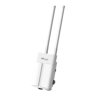
Milesight UG67 Quick Start Manual
Outdoor lorawan gateway
Hide thumbs
Also See for UG67:
- User manual (119 pages) ,
- Quick start manual (24 pages) ,
- Manual (13 pages)
Table of Contents
Advertisement
Quick Links
Advertisement
Table of Contents

Related Manuals for Milesight UG67


Summary of Contents for Milesight UG67
- Page 1 Outdoor LoRaWAN Gateway ® UG67 Quick Start Guide...
- Page 2 The related documents are available on Milesight website: https://www.milesight-iot.com Declaration of Conformity UG67 is in conformity with the essential requirements and other relevant provisions of the CE, FCC, and RoHS. For assistance, please contact Milesight technical support: Email: iot.support@milesight.com...
- Page 3 Revision History Date Doc Version Description October 30, 2020 V1.0 Initial version May 6, 2021 V1.1 Delete optional mark of LoRa antennas, add DC pinouts July 29, 2021 V1.2 Add antenna accessories and installation method 1. Delete Ethernet cable Oct. 31, 2022 V1.3 2.
-
Page 4: Table Of Contents
5.2 Configure the Wi-Fi Connection ......................15 5.3 Configure the Cellular Connection (Cellular Version Only) ............. 16 6. Packet Forwarder Configuration .........................18 7. Network Server Configuration ........................19 7.1 Connect UG67 to Milesight IoT Cloud ....................19 7.2 Connect UG67 to MQTT/HTTP Server ..................... 21... -
Page 5: Packing List
1. Packing List Before you begin to install the UG67 LoRaWAN ® Gateway, please check the package contents to verify that you have received the items below. 1 × UG67 1 × PoE Injector 1 × Mounting Bracket 4 × Wall Mounting Kits 1 ×... -
Page 6: Dimensions (Mm)
LoRaWAN Antenna Connector ® Vent Plug SIM Slot LED Area & Type-C Port & Reset Button SYS: System Indicator LoRa: LoRa Indicator LTE: Cellular Indicator DC Power Connector (Solar Connector) Ethernet Port (PoE) Mounting Bracket 2.2 Dimensions (mm) 2.3 LED Indicators Indication Status Description... -
Page 7: Reset Button
Static Green → Reset Release the button and wait. Rapidly Blinking Off → Static Green The gateway resets to factory default. 2.5 DC Power Connector UG67 supports 12 VDC or solar supply via M12 connector. Color Description Black White Reserved Yellow... -
Page 8: Ethernet Cable & Power Cable Installation
To install antenna to short mounting backboard, pass the antenna through the U-strap and fix the U-strap clamp to short mounting backboard with 2 screws at back of board and then screw flat washers, spring washers and nuts in front of the board. 3.3 Ethernet Cable &... -
Page 9: Power Supply
PoE injector: 3.5 Gateway Installation UG67 can be mounted to a wall or a pole. Before you start, make sure that your SIM card has been inserted, your antennas have been attached and all cables have been installed. -
Page 10: Pole Mounting
E. Hang the device to the mounting bracket via bracket mounting screws on the back of device, then screw the bracket screw to the bottom of the device. 3.5.2 Pole Mounting Preparation: mounting bracket (with a screw), short mounting backboard kit and other required tools. Fix the mounting bracket to short mounting backboard with 4 Phillips screws. -
Page 11: Login The Web Gui
4. Login the Web GUI UG67 provides web-based configuration interface for management. If this is the first time you configure the gateway, please use the default settings below: Username: admin Password: password 4.1 Wireless Access A. Enable Wireless Network Connection on your computer and search for access point “Gateway_******”... -
Page 12: Wired Access
4.2 Wired Access Connect PC to UG67 ETH port through PoE injector. The following steps are based on Windows 10 operating system for your reference. A. Go to “Control Panel” → “Network and Internet” → “Network and Sharing Center”, then click “Ethernet”... - Page 13 C. Open a Web browser on your PC (Chrome is recommended) and type in the IP address 192.168.23.1 50 to access the web GUI, enter the username and password, click “Login”. If you enter the username or password incorrectly more than 5 times, the login page will be locked for 10 minutes.
-
Page 14: Network Connection
5. Network Connection This section explains how to connect the gateway to network via WAN connection, Wi-Fi or cellular. 5.1 Configure the Ethernet Connection A. Go to “Network”→ “Interface” → “Port” page to select the connection type and configure Ethernet port information, click “Save &... -
Page 15: Configure The Wi-Fi Connection
5.2 Configure the Wi-Fi Connection A. Go to “Network” → “Interface” → “WLAN” and select “Client” mode. B. Click “Scan” to search for Wi-Fi access point. Select the available one and click “Join Network”. Note: please do use wired access method to access the web GUI, or you will fail to configure Wi-Fi setting. -
Page 16: Configure The Cellular Connection (Cellular Version Only)
E. Go to “Network” → ”Failover” → ”WAN Failover” to switch the wlan0 as main interface, then gateway can use the Wi-Fi to access the Internet. 5.3 Configure the Cellular Connection (Cellular Version Only) A. Go to “Network” → “Interface” → “Cellular” → “Cellular Setting” page to enable cellular settings. B. - Page 17 D. Go to “Status” → “Cellular” page to view the status of the cellular connection. If it shows “Connected”, it means the SIM has dialed up successfully. On the other hand, you can check the status of LTE indicator. If it keeps on light statically, it means SIM has dialed up successfully.
-
Page 18: Packet Forwarder Configuration
6. Packet Forwarder Configuration UG67 has installed multiple packet forwarders including Semtech, Chirpstack-Generic MQTT broker, etc. This section explains how to connect the gateway to network servers. Make sure the gateway connects to the network as shown in Section A. Go to “Packet Forwarder” → “General” page and click to add a network server. -
Page 19: Network Server Configuration
Milesight IoT Support portal. 7. Network Server Configuration UG67 can work as network server and transmit data to Milesight IoT Cloud or other platform via MQTT/HTTP/HTTPS. Make sure the gateway connects to the network as shown in Section 7.1 Connect UG67 to Milesight IoT Cloud... - Page 20 C. Go to “Network Server” → “General” page to enable the network server and “Milesight IoT Cloud” mode. D. Log in the Milesight IoT Cloud. Then go to “My Devices” page and click “+New Devices” to add gateway to Milesight IoT Cloud via SN. Gateway will be added under “Gateways” menu.
-
Page 21: Connect Ug67 To Mqtt/Http Server
The gateway is online on Milesight IoT Cloud. 7.2 Connect UG67 to MQTT/HTTP Server A. Go to “Packet Forwarder” → “General” page to enable the embedded network server. B. Go to “Packet Forwarder” → “Radio” page to configure center frequency and channels. The channels of the gateway and nodes need to be the same. - Page 22 D. Go to “Network Server”→”Application” to add a new application. After saving the application, you can select HTTP, HTTPS or MQTT protocol and fill in correspond server information to send data to another server. E. Go to “Profiles” page to add a new profile for the device.
- Page 23 F. Go to “Device” page and click “Add” to add LoRaWAN ® node devices. You can also click “Bulk Import” if you want to add many nodes all at once.
- Page 24 Click “Template Download” to download template file and add device information to this file. Application and device profile should be the same as you created on web page. Import this file to add bulks of devices. F. Go to “Packets” page to check the packets from LoRaWAN ®...
Need help?
Do you have a question about the UG67 and is the answer not in the manual?
Questions and answers