Fronius Smart Meter TS 100A-1 Operating Instructions Manual
Hide thumbs
Also See for Smart Meter TS 100A-1:
- Operating instructions manual (40 pages) ,
- Quick start manual (2 pages) ,
- Quick start manual (2 pages)

Related Manuals for Fronius Smart Meter TS 100A-1


Summary of Contents for Fronius Smart Meter TS 100A-1
- Page 1 Operating Instructions Fronius Smart Meter TS 100A-1 EN-US Operating instructions 42,0426,0350,EA 018-16072024...
-
Page 3: Table Of Contents
Error messages Commissioning Fronius SnapINverter General Connect to Fronius Datamanager 2.0 Configuring the Fronius Smart Meter TS as the primary meter Configuring the Fronius Smart Meter TS as a secondary meter Fronius GEN24 inverter General Installation using the web browser... -
Page 5: Safety Instructions
Safety Instructions... -
Page 7: Safety Rules
Safety rules Explanation of DANGER! Safety Instruc- tions Indicates an immediate danger. ▶ Death or serious injury may result if appropriate precautions are not taken. WARNING! Indicates a possibly dangerous situation. ▶ Death or serious injury may result if appropriate precautions are not taken. CAUTION! Indicates a situation where damage or injury could occur. -
Page 8: Environmental Conditions
Any safety devices that are not functioning properly must be repaired by an au- thorized specialist before the device is switched on. Never bypass or disable protection devices. For the location of the safety and danger notices on the device, refer to the sec- tion headed “General”... -
Page 9: General Information
General information... -
Page 11: Fronius Smart Meter Ts 100A-1
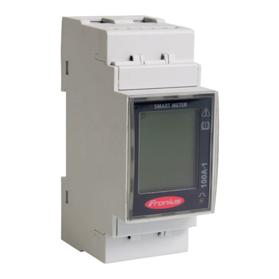
Fronius Smart Meter TS 100A-1 Device descrip- The Fronius Smart Meter TS is a bidirectional electricity meter which optimizes tion self-consumption and records the household's load curve. The Fronius Smart Meter TS provides a clear overview of a user's own power consumption in con- junction with the Fronius inverter, Fronius Datamanager, and Fronius data inter- face. -
Page 12: Information On The Device
Dangerous electrical voltage. Intended use The Fronius Smart Meter TS is a fixed piece of equipment for public grids of TN/TT systems and records self-consumption and/or individual loads in the sys- tem. The Fronius Smart Meter TS is required for systems with a battery storage... -
Page 13: Scope Of Supply
The installation is carried out on an indoor DIN rail with cor- responding back-up fuses, which are adapted to the cable cross-sections of the copper conductors and to the maximum current of the meter. The Fronius Smart Meter TS must only be operated in accordance with the specifications in the en- closed documentation and in accordance with local laws, regulations, provisions, standards, and within the limits of technical possibilities. - Page 14 Positioning at the feed-in point Positioning at the consumption point...
-
Page 15: Installation
Installation... -
Page 17: Installation
The update can be started via the in- verter web page or using Solar.web. If several Fronius Smart Meter TS are installed in the system, set the address "Setting the address on the Fronius Smart (see "Setting the address"... -
Page 18: Cabling
The Fronius Smart Meter TS consumes 10 - 30 mA, the nominal capacity of the disconnecting devices and the overcurrent protection is determined by the wire thickness, the mains voltage, and the required breaking capacity. Disconnecting devices must be mounted within sight and as close as possible to the Fronius Smart Meter TS;... -
Page 19: Fitting The Protective Cover For The Terminals
Connecting the Connect the data communication connections of the Fronius Smart Meter TS to data communic- the Modbus interface of the Fronius inverter using a network cable (type CAT5 ation cable to or higher). the inverter... -
Page 20: Terminating Resistors - Explanation Of Symbols
Use a mutual twisted cable pair for corresponding data lines (D+/D-, M0+/ M0-). On Fronius GEN24 inverters, the M0 and M1 inputs can be selected for this purpose. If the data lines are close to the mains cabling, use wires or cables that are designed for 300 to 600 V (never less than the operating voltage). -
Page 21: Terminating Resistors
Terminating res- Due to interference, it is recommended that terminating resistors are used as il- istors lustrated below to ensure proper functioning. -
Page 22: Mounting The Connection Cover
* The terminating resistor is integrated in the Fronius Smart Meter TS and is manufactured with a bridge between the M and T connections (T = termination). Mounting the Insert the connection covers into the connection cover guides and press firmly. -
Page 23: Modbus Participant - Fronius Snapinverter
Ohmpilot meters meters Multi-meter sys- If several Fronius Smart Meter TS are installed, a separate address must be set tem - Fronius for each (see Setting the address on the Fronius Smart Meter TS on page 29). SnapINverter... -
Page 24: Modbus Participant - Fronius Gen24
2 to 14. Different Fronius Smart Meter power categories can be used in combination. IMPORTANT! Max. Use 3 secondary meters in the system. To avoid interference, it is recom- mended to install the terminating resistors according to chapter... -
Page 25: Multi-Meter System - Fronius Gen24 Inverter
Ohmpilot meters meters Multi-meter sys- If several Fronius Smart Meter TS are installed, a separate address must be set tem - Fronius for each (see Setting the address on the Fronius Smart Meter TS on page 29). GEN24 inverter The primary meter is always assigned address 1. -
Page 26: Menu - Measured Variables
Data communication Data communication Location of the primary meter in the consumption branch. *Terminating resistor R 120 Ohm Data communication Data communication Location of the primary meter at the feed-in point. *Terminating resistor R 120 Ohm The following must be observed in a multi-meter system: Connect the primary meter and the battery to different channels (recom- mended). - Page 27 Scree Image Description Total active energy supplied** Effective power Total active energy drawn* Voltage Total active energy drawn* Current Total active energy drawn* Power factor (L = inductive, C = capacitive) Total active energy drawn* Frequency Total reactive energy drawn* Reactive power...
-
Page 28: Configuration Menu - Structure And Parameters
Scree Image Description Total reactive energy supplied** Reactive power Total active energy drawn* Average demanded power (dMd = demand), cal- culated for the set interval. The value remains unchanged for the entire interval. It is "0" in the first interval after the start. Maximum demanded power (P = Peak demand) that has been reached since the last reset Not used... -
Page 29: Setting The Address On The Fronius Smart Meter Ts
Settings that need to be configured. Setting the ad- Sym- dress on the Name Event Function Fronius Smart Scroll one screen forward, increase the value Meter TS by 1 Scroll one screen back, decrease the value Down/ by 1 Enter... -
Page 30: Error Messages
Press and hold "Down/Enter" for 2 seconds. Press "Up" or "Down/Enter" to ac- cess the P1 screen. Set password "2633" with "Up" and "Down/Enter" and confirm each in- dividual value with "Down/Enter". Note down the password. IMPORTANT! The password cannot be reset. Press "Up"... -
Page 31: Commissioning
Commissioning... -
Page 33: Fronius Snapinverter
The service password must be entered in order to access the "Meter" menu item. Three-phase or single-phase Fronius Smart Meter TS can be used. In both cases, the selection is made under the "Fronius Smart Meter" item. The Fronius Datamanager automatically identifies the meter type. -
Page 34: Configuring The Fronius Smart Meter Ts As A Secondary Meter
In the pop-up window, set the position of the meter (feed-in point or con- sumption point). For more information on the position of the Fronius Smart Positioning on page 13. Meter TS, see Click the "Ok" button when the OK status is displayed. If the Timeout status is displayed, try again. -
Page 35: Fronius Gen24 Inverter
"Device configura- tion" menu item. Three-phase or single-phase Fronius Smart Meter TS can be used. In both cases, the selection is made under the "Components" menu area. The meter type is de- termined automatically. A primary meter and several secondary meters can be selected. The primary meter needs to be configured first before a secondary meter can be selected. -
Page 36: Configuring The Fronius Smart Meter Ts As The Primary Meter
Follow the installation wizard in the individual sections and complete the in- stallation. Add the system components in Fronius Solar.web and start up the PV sys- tem. The network wizard and the product setup can be carried out independently of each other. - Page 37 Enter the name of the meter in the "Name" input field. In the "Category" drop-down list, select the category (producer or load). Click the "Add" button. Click the "Save" button to save the settings. The Fronius Smart Meter TS is configured as a secondary meter.
-
Page 38: Technical Data
Technical data Technical data Modbus transmission speed: 9600 baud Parity bit:none Software version: Fronius Datamanager 2.0 (from version 3.16.1 onwards) Fronius Symo Hybrid (from version 1.16.1 onwards) Measuring input Nominal voltage (1-phase) 230 V Operating range 161 - 276 V Self-consumption - voltage path (max. - Page 39 Insulation (EN IEC 62052-11, EN IEC 62053-21) Insulation voltage 4000 VAC RMS (1 min) Electromagnetic compatibility Emission test In acc. with EN IEC 62052-11, EN 50470-3 Immunity test In acc. with EN IEC 62052-11, EN 50470-3 Operating conditions Reference temperature 25 °C (±5 °C) Operating range -25 - 65 °C...
-
Page 40: Fronius Manufacturer's Warranty
Fronius manu- Detailed, country-specific warranty conditions are available atwww.fronius.com/ facturer's war- solar/warranty. ranty To obtain the full warranty period for your newly installed Fronius product, please register at www.solarweb.com.
Need help?
Do you have a question about the Smart Meter TS 100A-1 and is the answer not in the manual?
Questions and answers