Table of Contents
Advertisement
Quick Links
Advertisement
Table of Contents

Related Manuals for sauermann Si-C320


Summary of Contents for sauermann Si-C320
- Page 1 USER MANUAL Si-C320 MULTIFUNCTION TRANSMITTER sauermanngroup.com...
-
Page 3: Table Of Contents
Table of contents 1. Safety instructions ..............................5 1.1 Warnings ................................5 1.2 Environment protection ............................ 5 1.3 Symbols used ..............................5 2. Conformity and standard ............................6 2.1 FCC rules ................................. 6 2.2 Canadian standard ............................6 3. Introduction ................................7 3.1 Description of the transmitter ........................... - Page 4 11.1 Instrument and probes/modules information ....................27 11.2 Adjustment and calibration information ......................27 11.3 Probe update ............................... 27 12. Modbus ................................28 12.1 Configuration of parameters ......................... 28 12.2 Functions ..............................28 12.3 Data format ..............................28 12.4 Description of function and Modbus connections ..................28 12.4.1 Device ..............................
-
Page 5: Safety Instructions
Send back the device at its end of working life for waste collection center of electrical and electronic components (according to local regulations), or send it back to Sauermann to ensure a required waste collection in the respect of the environment. -
Page 6: Conformity And Standard
The transmitter complies with 2015/863 EU (RoHS 3). Document available on request. Hereby, Sauermann Industrie SAS declares that the radio equipment type Si-C320 is in compliance with Directive 2014/53/EU. The full text of the EU declaration of conformity is available at the following internet address: sauermanngroup.com. -
Page 7: Introduction
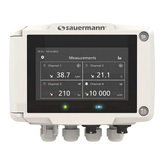
3. Introduction 3.1 Description of the transmitter 3.1.1 Overall description 1 - Touch screen 2 - Access to device settings menu 3 - Transmitter power indicator 4 - Pressure connection 5 - Pressure connection 6 - Cable glands 7 - Probe connection 1 8 - Probe connection 2 9 - Wireless connection light 10 - Access to Graph view... -
Page 8: Connections
There is no alarm configured and activated for the channel An alarm is configured and activated for the channel Channel 2 In case of alarm, the measurement concerned by the alarm will be in red on the screen 37.5 °C In case of faulty communication with the transmitter, the concerned channel's background Channel 3 will change to orange. -
Page 9: Mounting
4. Mounting The transmitter must be mounted before any wire connections. The transmitter must not be powered before mounting it. To install the transmitter on a wall: • Fix the stainless steel plate to the wall (drilling: Ø 8 mm, screws and wall-plugs supplied). •... -
Page 10: Electrical Connections
5. Electrical connections Electrical connections are as per NF C 15-100 standard. This connection must be made by a trained and qualified technician. Whilst making the connec- tion, the transmitter must not be energized. The presence of a switch or a circuit breaker up- stream the device is compulsory. -
Page 11: First Start-Up
Please connect the probe(s) before con guring the channel(s) Next The transmitter is set. You can connect a probe to set a channel. For models without display, please use the app to set your transmitter. Download Sauermann Control App First Start-up... -
Page 12: Connect A Probe
For models without display, please use the app to set your channel. Download Sauermann Control App Activate the channel taping ‘’Measures’’, ‘’Units’’, ‘’Coef cient’’ and First Start-up... -
Page 13: Set An Output
Measures Channel 2 27.7 For models without display, please use the app to set your output. Download Sauermann Control App Next 6.5 Disconnect a probe • Turn the ring (c) of the probe connector to the left. • Pull the probe connector (a) away from the transmitter connector (b). -
Page 14: Transmitter Features
7. Transmitter features 7.1 General features 24 V ±10% Power supply Warning: risk of electric shock 4 x 4-20 mA, 0-20 mA, 0-10 V or 0-5 V analogue outputs Common mode voltage <30 V Outputs Maximum load: 500 Ω (0/4-20 mA) Minimum load: 1 KΩ... -
Page 15: Dimensions
76.65 mm (3.02’’) 158.25 mm (6.23’’) 7.4 Possible optional measurements The following probes and modules are available as an option for Si-C320 transmitters. For further details please see the probes technical data sheet for class 320 transmitters. Probes / modules... -
Page 16: Set The Transmitter
8. Set the transmitter "Device Settings" menu allows to set the following items for the transmitter: • Language • Country • Date, time and time zone • Brightness To access to this menu: • Tap on the measurement screen. • Enter the security code. Default security code is 0101. -
Page 17: Set Inputs And Outputs
9. Set inputs and outputs "I/O Configurations" menu allows to set the following items: • Channels: activate and set the probes and modules connected to the transmitter • Outputs: activate and set outputs corresponding to the channels • Probes and Modules: define normative values according to probes and modules connected to the transmitter and define some parameters linked to probes and modules •... -
Page 18: Perform An Output Diagnostic
"I/O Configurations" menu is displayed. • Tap "Outputs". • Tap "Analog Outputs". • Tap the desired output (Output 1, 2, 3 or 4 depending on the number of the previously configured channel). Features of the output are displayed. • Tap on the top right of the screen to activate the output •... -
Page 19: Set The Digital Output (Modbus Rtu)
If the deviations are too large (> 0.05 V or > 0.05 mA) between the signal issued and the value displayed on the multimeter, we recommend that you return the transmitter to our factory. 9.2.3 Set the digital output (Modbus RTU) "I/O Configurations"... -
Page 20: Configure A Differential Pressure Module
• 0 and 4000 hPa • 0 and 4000 mbar • 0 and 3000.24 mmHg • 0 and 10 000 m (altitude) 9.3.3 Configure a differential pressure module A differential pressure module must be connected to the transmitter. Select the measuring device: "I/O Configurations"... - Page 21 For a custom coefficient (airflow coefficient): • Tap "Coefficient" to enter an airflow coefficient, then tap the back arrow on the left of the screen. This airflow coefficient allows to calculate an airflow from the pressure. It is indicated by the manufacturer of the devices supplied with pressure connections (+ and -).
-
Page 22: Set The Alarms
The pressure integration must be between 0 and 9. Enter a correction factor: The correction factor allows to adjust the transmitter according to data in air velocity of the installation. How to calculate it? For example, the air velocity in your section is 17 m/s and the transmitter displays 16.6 m/s. The coefficient to apply is 17 / 16,6, it means 1.024. -
Page 23: Set The Autozero
a low threshold at 20 Pa and a hysteresis at 5 Pa: the alarm stay triggered until the value goes below 75 (or up to 25). • Tap "Alarm parameters". • Tap "Hysteresis". • Enter the hysteresis. The hysteresis must be between the low threshold and the high threshold (only if two thresholds are config- ured). - Page 24 • Tap to activate the relay. • Select "Alarm 1", "Alarm 2", "Alarm 3" or "Alarm 4" to assign the relay activation to an alarm previously configured. • Tap "Security". The outputs relays are by default in negative security: the relay is energized during an alarm condition. It is possible to switch the relays in positive security: the relay is de-energized during an alarm condi- tion or a power cut.
-
Page 25: Security And Connectivity
Default security code is 0101. This code can be modified in "Security/Connectivity" menu. See chapter 9.2 on page 25. 10.1 Wireless communication It's possible to activate and deactivate the wireless communication. The wireless communication must be activated to use the Sauermann Control app. "Security/Connectivity" menu is displayed. • Tap to activate the wireless communication. - Page 26 Feature Default value Channel N output Output type 4-20 mA Channel N range Channel N's name Channel N Alarms Display brightness Graph timespan 24 hours Wireless communication Access code to enter the configuration menu 0101 Modbus output Modbus address Modbus baud rate 9600 bps Date and time Last set value...
-
Page 27: Information About Transmitter, Probes And Modules
11. Information about transmitter, probes and modules "Information" menu allows to access to information such as serial numbers, firmware version, date of last adjust- ment and calibration, date of next service,... To access to this menu: • Tap on the measurement screen. •... -
Page 28: Modbus
12. Modbus 12.1 Configuration of parameters • Communication speed: between 2400 and 115200 bauds, 9600 bauds by default • Data bits: 8 bits • Stop bit: 1 bit • Parity: None • Flow control: None • Transmitter addressing: between 1 and 255 (automatically answers the requests from address 0) •... -
Page 29: Channels
1090 Probe 1 version 1100 Probe 2 version 1110 Module version 1120 Backlit value In percent, from 0 to 100. 1150 Graph period From 0 to 3. 1160 Graph channel 1200 Language 1300 Timestamp 1310 Time offset 1320 Date format 1330 Hour format 1350... -
Page 30: Outputs
12.4.3 Outputs Modbus Register type Description Possibilities 3000 Analog output selection of the 4-20 mA / 0-20 mA / 0-10 V / 0-5 V channel 1 3100 Analog output selection of the 4-20 mA / 0-20 mA / 0-10 V / 0-5 V channel 2 3200 Analog output selection of the... -
Page 31: Probes And Module Parameters
4260 BOOLEAN Enabled/Disabled 4280 BOOLEAN Audible alarm 4290 Acknowledgement duration Alarm 4 4300 Alarm mode 0: None, 1: Min, 2: Max, 3: Min/Max 4310 Hysteresis 4320 Threshold Up 4330 Threshold Down 4340 Delay Time 4350 Delay End 4360 BOOLEAN Enabled/Disabled 4380 BOOLEAN Audible alarm... - Page 32 6150 Type of section used for air ve- 0: rectangular, 1: circular, 2: other (set locity and airflow probes airflow coefficient instead), 3: None (not configured) 6160 Unit for section diameter, section length and section width 6170 Section diameter value in meters From 0.001 to 3.
- Page 33 6430 Manual temperature compensa- From -50 to 50, in Celsius degrees. tion value in Celsius degrees 6440 Correction factor used for air ve- From 0.2 to 2] - Used for air velocity locity and airflow probes and airflow probes (default = 1). 6450 Type of section used for air ve- 0: rectangular, 1: circular, 2: other (set...
- Page 34 Module 6600 Lower limit of probe range, for for maximum 10 measures (@6600: each available measure lower range of measure 1, @6602: lower range of measure 2, etc…) 6620 Upper limit of probe range, for for maximum 10 measures (@6600: each available measure upper range of measure 1, @6602: upper range of measure 2, etc…)
-
Page 35: Normative Values
6800 Airflow coefficient (allows to cal- From 0.1 to 9999.9. culate an airflow from the pres- sure) 12.4.6 Normative values Modbus Register type Description Possibilities 6900 Normative Value 12.4.7 Alarms Modbus Register type Description Possibilities 7000 BOOLEAN Alarm 1 raised 7010 Channel 1 measured value In unit selected for the channel (cf... -
Page 36: Maintenance And Precautions For Use
13. Maintenance and precautions for use 13.1 Maintenance Please avoid any aggressive solvents. Please protect the transmitter and its probes from any cleaning product con- taining formalin, that may be used for cleaning rooms or ducts. 13.2 Precautions for use Please always use the device in accordance with its intended use and within parameters described in the user man- ual in order not to compromise the protection ensured by the device. - Page 37 Sauermann Industrie Sauermann Italia srl SU ZA Bernard Moulinet Via Golini 61/10 24700 Montpon 40024 Castel S.Pietro Terme (BO) France T. (+39)-051-6951033 T. +33 (0)5 53 80 85 00 F. (+39)-051-942254 services@sauermanngroup.com services@sauermanngroup.com Sauermann Ibérica Sauermann NA C/Albert Einstein 33.
Need help?
Do you have a question about the Si-C320 and is the answer not in the manual?
Questions and answers