Table of Contents
Advertisement
Quick Links
Advertisement
Table of Contents

Subscribe to Our Youtube Channel
Related Manuals for sauermann Si-CPE320


Summary of Contents for sauermann Si-CPE320
- Page 1 USER MANUAL Si-CPE320 MULTIFUNCTION PANEL TRANSMITTER sauermanngroup.com...
-
Page 3: Table Of Contents
Table of contents 1. Safety instructions ..............................5 1.1 Warnings ................................5 1.2 Environment protection ............................ 5 1.3 Symbols used ..............................5 2. Conformity and standard ............................6 2.1 FCC rules ................................. 6 2.2 Canadian standard ............................6 3. Introduction ................................7 3.1 Description of the transmitter ........................... - Page 4 11.2 Adjustment and calibration information ......................26 11.3 Probe update ............................... 26 12. Modbus ................................27 12.1 Configuration of parameters ......................... 27 12.2 Functions ..............................27 12.3 Data format ..............................27 12.4 Description of function and Modbus connections ..................27 12.4.1 Device ..............................
-
Page 5: Safety Instructions
Send back the device at its end of working life for waste collection center of electrical and electronic components (according to local regulations), or send it back to Sauermann to ensure a required waste collection in the respect of the environment. -
Page 6: Conformity And Standard
The transmitter complies with 2015/863 EU (RoHS 3). Document available on request. Hereby, Sauermann Industrie SAS declares that the radio equipment type Si-CPE320 is in compliance with Directive 2014/53/EU. The full text of the EU declaration of conformity is available at the following internet address: sauermanngroup.com. -
Page 7: Introduction
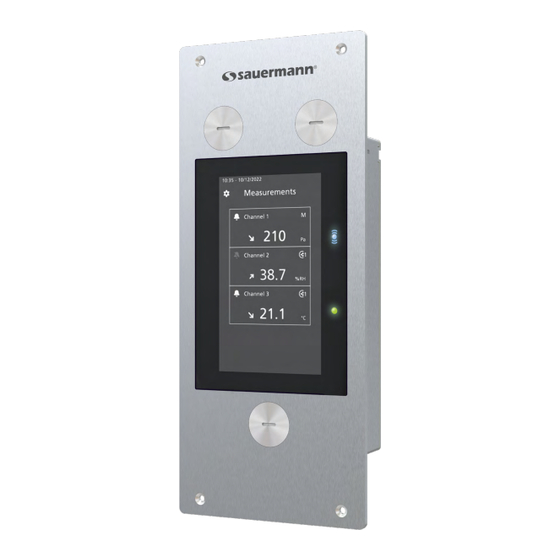
3. Introduction 3.1 Description of the transmitter 3.1.1 Overall description 1 - Touch screen 2 - Access to device settings menu 3 - Software connection 4 - Transmitter power indicator 5 - Wireless connection indicator 6 - Front + pressure connector 7 - Front - pressure connector 8 - Probe connector 3.1.2 Screen description... -
Page 8: Connections
An alarm is configured and activated for the channel Channel 2 In case of alarm, the background of the channel concerned by the alarm turns red on the 37.5 screen. °C In case of error, the concerned channel's background will change to orange. By tapping on Channel 3 the screen a message with additional information about the problem is displayed. -
Page 9: Mounting
• Insert the transmitter into the wall. • Fix it with the 4 screws (supplied with the transmitter). The fixing screw is in a plastic bag into the box of the Si-CPE320. Type of screw: Cruciform screw Ø 3.5 x 12 mm 82 mm (3.23’’) -
Page 10: Electrical Connections
OUT2 OUT2 OUT1 Power supply terminal block 12 11 10 5. Electrical connections Electrical connections are as per NF C 15-100 standard. This connection must be made by a formed and qualified technician. Whilst making the connec- tion, the transmitter must not be energized. The presence of a switch or a circuit breaker up- stream the device is compulsory. -
Page 11: First Start-Up
‘’Next’’. You can connect a probe to set a channel. Download Sauermann Control App 6.2 Connect a probe • After removing the protection cap on the transmitter connector, present the probe connector (a) with its arrow and padlock face to the transmitter connector (b). -
Page 12: Set A Channel
‘’Next’’. Parameters to set are con gure outputs. Tap the required needs then tap the now available. channel. back arrow on the top left. Download Sauermann Control App 6.4 Set an output First Start-up... -
Page 13: Disconnect A Probe
Download Sauermann Control App 6.5 Disconnect a probe • Turn the ring (c) of the probe connector to the left. • Pull the probe connector (a) away from the transmitter connector (b). -
Page 14: Transmitter Features
7. Transmitter features 7.1 General features 24 V ±10% Power supply Warning: risk of electric shock 3 x 0/4-20 mA or 3 x 0-5/10 V (4 wires) Common mode voltage Outputs Maximum load: 500 Ω (0/4-20 mA) Minimum load: 1 KΩ (0-5/10 V) Galvanic isolation On the output Consumption with... -
Page 15: Dimensions
80 mm (3.15’’) 44 mm (1.73’’) 7.4 Possible optional measurements The following probes and modules are available as an option for Si-CPE320 transmitters. For further details please see the probes technical data sheet for class 320 transmitters. Probes / modules... -
Page 16: Set The Transmitter
8. Set the transmitter "Device Settings" menu allows to set the following items for the transmitter: • Language • Country • Date, time and time zone • Brightness To access this menu: • Tap on the measurement screen. • Enter the security code. Default security code is 0101. -
Page 17: Set Inputs And Outputs
9. Set inputs and outputs "I/O Configurations" menu allows to set the following items: • Channels: activate and set the probes and modules connected to the transmitter • Outputs: activate and set outputs corresponding to the channels • Probes and Modules: define normative values according to probes and modules connected to the transmitter and define some parameters linked to probes and modules •... -
Page 18: Perform An Output Diagnostic
• Tap "Outputs". • Tap "Analog Outputs". • Tap the desired output (Output 1, 2 or 3 depending on the number of the previously configured channel). Features of the output are displayed. • Tap on the top right of the screen to activate the output •... -
Page 19: Set The Digital Output (Modbus Rtu)
• Tap the required value. The values proposed will depend on the type of output previously selected. For example, if the output type is 4-20 mA, proposed values will be 4 mA, 12 mA and 20 mA. If the deviations are too large (> 0.05 V or > 0.05 mA) between the signal issued and the value displayed on the multimeter, we recommend that you return the transmitter to our factory. -
Page 20: Configure The Differential Pressure Module
• Tap "Unit" to select the atmospheric pressure unit. • Tap "Atmo pressure" to enter a value. This value must be between: • 0 and 4000 hPa • 0 and 4000 mbar • 0 and 3000.24 mmHg • 0 and 10 000 m (altitude) 9.3.3 Configure the differential pressure module Select the measuring device: "I/O Configurations"... - Page 21 • Tap "Coefficient" to enter an airflow coefficient, then tap the back arrow on the left of the screen. This airflow coefficient allows to calculate an airflow from the pressure. It is indicated by the manufacturer of the devices supplied with pressure connections (+ and -). From the square root of the measured pressure (Delta P) and from this coefficient, you get the airflow.
-
Page 22: Set The Alarms
The coefficient to apply is 17 / 16,6, it means 1.024. "I/O Configurations" menu is displayed. • Tap "Probes & Modules". The screen displays the connected probes and modules. • Tap the line corresponding to the pressure module. • Tap "Integr. & Correction". •... -
Page 23: Set The Autozero
Set the alarm acknowledgement Alarm acknowledgement: when an alarm goes off, it is possible to acknowledge it by pressing the value in alarm on the screen: the audible alarm, if activated, turns off and the displayed value remains in red during the acknowl- edgement duration. -
Page 24: Security And Connectivity
Default security code is 0101. This code can be modified in "Security/Connectivity" menu. See chapter 9.2 on page 24. 10.1 Wireless communication It's possible to activate and deactivate the wireless communication. The wireless communication must be activated to use the Sauermann Control app. "Security/Connectivity" menu is displayed. • Tap to activate the wireless communication. - Page 25 Feature Default value Channel N output Output type 4-20 mA Channel N range Channel N's name Channel N Alarms Display brightness Graph timespan 24 hours Wireless communication Access code to enter the configuration menu 0101 Modbus output Modbus address Modbus baud rate 9600 bps Date and time Last set value...
-
Page 26: Information About Transmitter, Probes And Module
11. Information about transmitter, probes and module "Information" menu allows to access to information such as serial numbers, firmware version, date of last adjust- ment and calibration, date of next service,... To access this menu: • Tap on the measurement screen. •... -
Page 27: Modbus
12. Modbus 12.1 Configuration of parameters • Communication speed: between 2400 and 115200 bauds, 9600 bauds by default • Data bits: 8 bits • Stop bit: 1 bit • Parity: None • Flow control: None • Transmitter addressing: between 1 and 255 (automatically answers the requests from address 0) •... -
Page 28: Channels
1310 Time offset 1320 Date format 1330 Hour format 1350 BOOLEAN Sound 1400 BOOLEAN Keypad locking 1410 Safety code 1500 Modbus slave number 1510 Modbus speed communication 1710 BOOLEAN Activation of the Modbus option 1900 BOOLEAN Back to factory configuration 1910 Delay time (in min) between 2 From 10 to 60. -
Page 29: Alarms
12.4.4 Alarms Modbus Register type Description Possibilities Alarm 1 4000 Alarm mode 0: None, 1: Min, 2: Max, 3: Min/Max 4010 Hysteresis 4020 Threshold Up 4030 Threshold Down 4040 Delay Time 4050 Delay End 4060 BOOLEAN Enabled/Disabled 4080 BOOLEAN Audible alarm 4090 Acknowledgement duration Alarm 2... -
Page 30: Normative Values
6070 Custom coefficient for pressure From 0.0001 to 9.9999. device plugged in order to deter- mine the air velocity 6080 Room volume unit 6090 Room volume value in cubic In cubic meter. meter used for computing air re- newing rate (ACR) 6100 Measurement integration From 0 to 9. - Page 31 7040 Channel 1 error reason 0: none, 1: internal, 2: not configured, 3: measure, 4: unplugged probe, 5: invalid probe, 6: probe to update 7100 BOOLEAN Alarm 2 raised 7110 Channel 2 measured value In unit selected for the channel (cf register 2100).
-
Page 32: Maintenance And Precautions For Use
13. Maintenance and precautions for use 13.1 Maintenance Please avoid any aggressive solvents. Please protect the transmitter and its probes from any cleaning product con- taining formalin, that may be used for cleaning rooms or ducts. 13.2 Precautions for use Please always use the device in accordance with its intended use and within parameters described in the user man- ual in order not to compromise the protection ensured by the device. - Page 33 Sauermann Industrie Sauermann Italia srl SU ZA Bernard Moulinet Via Golini 61/10 24700 Montpon 40024 Castel S.Pietro Terme (BO) France T. (+39)-051-6951033 T. +33 (0)5 53 80 85 00 F. (+39)-051-942254 services@sauermanngroup.com services@sauermanngroup.com Sauermann Ibérica Sauermann NA C/Albert Einstein 33.
Need help?
Do you have a question about the Si-CPE320 and is the answer not in the manual?
Questions and answers