
Related Manuals for Creality Ender-3 V3 KE


Summary of Contents for Creality Ender-3 V3 KE
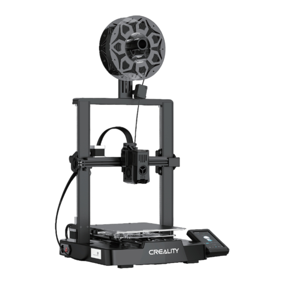
- Page 1 Create reality,achieve dreams Ender-3 V3 KE Ender-3 V3 KE 3D Printer User Manual V1.0...
- Page 2 Creality is always ready to provide you with high-quality services. If you encounter any issues or have any questions when using our products, please use the contact information at the end of this manual to contact us. To further improve your user experience, you can find more about our devices via the following methods:...
- Page 3 Instructions for Use 1. Do not use this printer by methods or operations that are not described in this manual, otherwise it may result in accidental injury or property damage; 2. Do not place this printer near flammable materials, explosive materials or high heat sources. Please place this printer in a ventilated, cool and low-dust environment;...
-
Page 4: Table Of Contents
Contents ······················································································· 1. About the Printer 01-01 ····························································································· 2. Parts List 02-02 ····················································································· 3. Assembly Procedure 03-08 ························································································ 3.1 Gantry frame 03-03 ······················································································· 3.2 Display screen 04-04 ······························································ Material rack and filament detection assemblies 05-05 ···················································································· 3.4 Equipment Wiring 06-06 ···················································································... -
Page 5: About The Printer
1.About the Printer X-axis support Print platform X-axis tensioner Power outlet Display screen X-axis kit Voltage regulation gear X-axis motor USB port 1 Y-axis tensioner Extruder kit Coupler Material rack and filament USB port 2 Z-axis motor Power switch detection assemblies... -
Page 6: Parts List
2.Parts List Base component Gantry frame Display screen Material rack and filament Filament tube component detection assemblies Accessory kit Hexagon Socket Head Hexagon Socket Hexagon Socket Hexagon Socket Head Cap Screw with Spring Button Head Screw Button Head Screw Cap Screw M3*8 ×2 Washer M3*14 ×6 M4*10 ×3 M5*8 ×2... -
Page 7: Assembly Procedure
3.Assembly Procedure 3.1 Gantry frame ① The gantry is placed in the base ③ Secure the bottom shell with card slot, and the broken material M3*14 screws. detection port is passed through the bottom shell pair interface, and it is fixed with M3*14 screws;... -
Page 8: Display Screen
3.Assembly Procedure 3.2 Display screen Put the display screen on the right side of the bottom assembly, align the screw holes and secure with M4*10 screws, then connect the display wiring. Display wiring Use M4*10 screws... -
Page 9: Material Rack And Filament Detection Assemblies
3.Assembly Procedure 3.3 Material rack and filament detection assemblies ① Install the material rack and material ② Secure the material rack and filament detection X轴电机 barrel according to the diagram; assembly onto the gantry frame, align the screw holes and lock it with M5*8 screws; ④... -
Page 10: Equipment Wiring
3.Assembly Procedure 3.4 Equipment Wiring 断料检测开关 ① First insert the nozzle wire into the nozzle adapter plate , then install the FFC fixing clip assembly, and use M3*8 screws to fix and lock it; Extruder adapter 喷头转接板 board X-axis motor ④... -
Page 11: Printer Auto Guidance
4.Printer Auto Guidance 4.1 Auto Guidance Note: The current interface is for reference only. As the functions are constantly upgraded, please refer to the latest firmware UI on the official website. -
Page 12: Auto Detection
4.Printer Auto Guidance 4.2 Auto Detection Note: The current interface is for reference only. As the functions are constantly upgraded, please refer to the latest firmware UI on the official website. -
Page 13: About The User Interface
Z轴电机 4.Printer Auto Guidance 4.3 About the User Interface Hotbed temperature Note: The current interface is for reference only. Nozzle temperature As the functions are constantly upgraded, please refer to the latest firmware UI on the official website. Home Parameters can be manually set Use the preparation interface to set functions such as axis movement, Prepare... - Page 14 4.Printer Auto Guidance Local and USB flash drive Print file model files can be managed via the print file preview preview interface. Long press on the model to select multiple options and copy locally *Up to a maximum of 3 models can be copied Model fan switch Print interface Note: The current interface is for reference...
- Page 15 4.Printer Auto Guidance Machine system, network, and camera settings can be configured through the settings interface. V1.1.0.9 Customer Access the customer service interface to view Service FAQs, manuals, and log management. Note: The current interface is for reference only. As the functions are constantly upgraded, please refer to the latest firmware UI on the official website.
-
Page 16: First Printing
5.First Printing 5.1 Filament Loading 5.1.1 Load filaments ② Before first printing, cut the front of the filament at 45° and break it off straight; ③ Thread the straightened filaments through the ① Perform nozzle warm-up; filament detection switch; PUSH ④... - Page 17 5.First Printing 5.1.2 Auto feed 5.1.3 Auto retreat...
-
Page 18: Lan Printing
5.First Printing 5.2 LAN printing ※ Install Creality Print slicing software by opening the random data on the USB flash drive. ※ Log in to the official website to download for installation:https://www.crealitycloud.com/software-firmware/software?type=7 Add Printer series series series series Sonic Pad... - Page 19 5.First Printing Ender-3 V3 KE Ender-3 V3 KE ⑤ Set filament type ⑥ Adjust parameter configuration and click on "Slice" ⑦ After slicing is done, click on "LAN printing" ⑧ Add equipment: can be added either by "scan to add"...
- Page 20 5.First Printing Ender-3 V3 KE Ender-3 V3 KE Ender-3 V3 KE Ender-3 V3 KE ⑧ Add a device: a. Scan Add → Select device ⑨ Device list Ender-3 V3 KE ⑧ Add a device: b. Add a device by manually ⑩...
-
Page 21: Usb Flash Drive Printing
5.First Printing USB flash drive printing ② Select the model from the ③ Click on "Print" ④ Printing... ① Insert the USB flash USB flash drive drive into any USB port Tips: 1. For details on using the software, please refer to the slicing software user manual on the USB flash disk. -
Page 22: Equipment Maintenance
6.Equipment Maintenance 6.1 Platform plate removal and maintenance ① a. When printing is finished, wait for the platform plate to ② If there are residual filaments on the ③ If the first layer of the model is not cool before removing the printing platform with the model platform plate, scrape them off... -
Page 23: Nozzle Replacement
6.Equipment Maintenance 6.3 Nozzle Replacement ① Remove the silicone ② Remove the old nozzle ③ Mount a new nozzle ④ Mount the silicone protective cover protective cover Warnings: 1. To replace the nozzle, you need to preheat the nozzle first; 2. -
Page 24: Equipment Parameters
100-120V~, 200-240V~, 50/60Hz Power Loss Recovery Filament detection Printing Method LAN printing/USB flash drive printing/APP printing Slicing Software STL/OBJ/3MF/AMF File Format Creality print/Cura 5 and later/Simplify3D Operating Systems Windows/Mac OS/Linux Language English/ Español/ Deutsche/ Français/ Pусский/ Português/ Italiano/ Türk/ 日本語/ 中文... -
Page 25: Circuit Connecting
8.Circuit Connecting Storage card slot Normally open fan 30P flexible flat cable 10P flexible flat cable Z-axis motor port Filament detection Type-c port Fuse DC 24V LCD display port Hotbed Hotbed thermistor port Interface to Z limit port Touch screen interface height alignment module... - Page 26 FCC Statement FCC Caution: Any Changes or modifications not expressly approved by the party responsible for compliance could void the user's authority to operate the equipment. This device complies with part 15 of the FCC Rules. Operation is subject to the following two conditions: (1) This device may not cause harmful interference, and (2) this device must accept any interference received, including interference that may cause undesired operation.
- Page 27 Due to the differences between different machine models, the actual objects and the images can differ. Please refer to the actual machine. The final explanation rights shall be reserved by Shenzhen Creality 3D Technology Co., Ltd. 18th Floor, JinXiuHongDu Building, Meilong Road, Xinniu Community, Minzhi Street, Longhua District, Shenzhen City, China.
Need help?
Do you have a question about the Ender-3 V3 KE and is the answer not in the manual?
Questions and answers