FIBARO FGFS-101 - Flood Sensor Manual
- Operating manual (21 pages) ,
- Operating manual (2 pages) ,
- Operating manual (21 pages)
Advertisement
Description and features
 NOTE
NOTE
This device may be used with all devices certified with the Z-Wave Plus certificate and should be compatible with such devices produced by other manufacturers.
NOTE
FIBARO Flood Sensor is a Security Enabled Z-Wave Plus product and a Security Enabled Z-Wave Controller must be used in order to fully utilize the product.
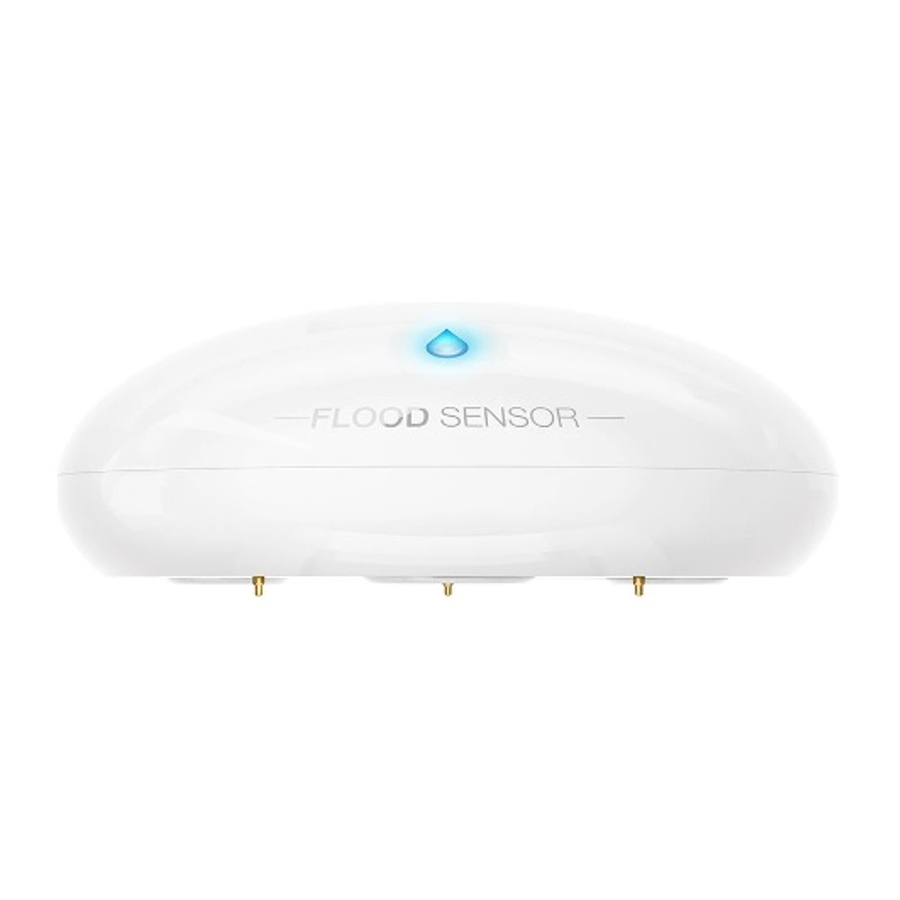
FIBARO Flood Sensor is a universal, Z-Wave Plus compatible, flood and temperature sensor. The device can be powered using battery, 12/24V DC power supply or both. Flood alarm is sent to the Z-Wave network devices or additionally to any external system through opening a nC contact using the external power supply.
The device has built in temperature sensor that allows to monitor ambient temperature. FIBARO Flood Sensor is designed to be placed on the floor or mounted on a wall (in this case Flood Sensor probes should be extended using addition wire). The device has a built-in visual LED indicator and an acoustic alarm.
In addition, the sensor is equipped with a tilt sensor reporting tilt or movement to the main controller e.g. when someone has taken the Sensor from its original location.
FIBARO Flood Sensor is sink-proof, which means it drifts on the water surface and keeps on sending alarm signal in case of substantial inundation of water.
Main features of FIBARO Flood Sensor:
- compatible with any Z-Wave or Z-Wave Plus Controller,
- supports protected mode (Z-Wave network security mode) with AES- 128 encryption,
- may be connected to any external system (potential free output terminal),
- extremely easy installation - simply put on a surface prone to flooding,
- may be installed anywhere - flood sensor's contacts extended with a wire,
- battery or VDC powered. When connected to an external 12/24V DC power source, the battery serves as an emergency power source,
- theft protection - tilt or moving is reported to the Z-Wave network or external system's controller,
- two operating modes - flood/temperature sensor or just a temperature sensor,
- alarm is signalled by sound, visual indicator (LED diode) and Z-Wave.
FIBARO Flood Sensor is a fully compatible Z-Wave Plus device.

Basic activation
- Turn the cover counter-clockwise and open it.
![]()
- Remove the battery blocker.
![]()
- Flood Sensor will confirm being powered with a short beep and a LED blink.
- Add the device (see "Adding/removing the device").
- Close the cover and turn it clockwise.
![]()
- Place the sensor on a surface prone to flooding. Three electrodes underneath the device should evenly touch the surface.


NOTE
When powered, the device will indicate Z-Wave status with colour of LED:
- Green - the device is already added to the Z-Wave network.
- Red - the device is not added to any Z-Wave network.
NOTE
After completing installation it is recommended to test sensor's operation by placing the entire sensor or its probes' extension wire onto water surface.
NOTE
When changing the Sensor's location, it's recommended to wake up the device and reconfigure the Z-Wave network by triple clicking the TMP button or removing and inserting the battery.
Adding/removing the device
Adding (Inclusion) - Z-Wave device learning mode, allowing to add the device to existing Z-Wave network.
To add the device to the Z-Wave network:
- Open the cover.
- Place the Sensor within the direct range of your Z-Wave controller.
- Set the main controller in (security/non-security) add mode (see the controller's manual).
- Quickly, three times press the TMP button.

- Wait for the adding process to end.
- Successful adding will be confirmed by the Z-Wave controller's message.
![information]() NOTE
NOTE
Adding in security mode must be performed up to 2 meters from the controller.
![information]() NOTE
NOTE
In case the Sensor is not added, please reset the Sensor and repeat the adding procedure.

Removing (Exclusion) - Z-Wave device learning mode, allowing to remove the device from existing Z-Wave network.
To remove the device from the Z-Wave network:
- Open the cover.
- Place the Sensor within the direct range of your Z-Wave controller.
- Set the main controller into remove mode (see the controller's manual).
- Quickly, three times press the TMP button.
![]()
- Wait for the removing process to end.
- Successful removing will be confirmed by the Z-Wave controller's message.
![information]() NOTE
NOTE
Removing Flood Sensor from the Z-Wave network restores all the default parameters of the device.

Diagrams and connection
 Connecting the FIBARO Flood Sensor in a manner inconsistent with manual may cause risk to health, life or material damage.
Notes for the diagrams and probes marking:

+12V - 12 / 24 VDC positive terminal
GND - negative (ground) terminal
ALARM NC - potential-free flood sensor terminals (for wired systems)
TAMP NC - potential-free tamper terminals (for wired systems)
SENS1, SENS2 - flood sensor electrodes' terminals
TMP - tamper button (used to add/remove the device)
Connection to a constant power source:


Connect while observ ing wiring diagram shown in this manual only. Incorrect wiring may be dangerous or result in the device breakdown.
Remember to keep the device away from water or protect holes for wires from water to avoid destroying the device.
To prevent accidental pulling out make certain that cables are firmly attached to the wire connectors and screws are properly tightened.
Make sure to secure the power cord after connecting it to the terminal.
NOTE
The TMP button has two functions:
- Adding / Removing the device to / from the Z-Wave network,
- Tamper contact for 4th Association Group. When a sensor is added to the Z-Wave network, cover open alarm may be activated (according to parameter 74 settings).
Connection with external wired system:

NOTE
ALARM NC and TAMP NC connectors may be used as end-of-line protective loop's terminals.
Extending Flood Sensor contacts with a wired probe:
If you want the device to be mounted on a wall or in a distance from flooding source, sensor should be extended using an external probe (not included).
We recommend using extension probes or cables designed to detect water. Probes ends should be coated with non-corrosive metal. Connection wires should not be longer than 3m with 18-26AWG (0.14 - 0.82mm 2 ). It applies also to VDC power source wires.

NOTE
Mounting screws shown in a diagram are not included in the package. Choose a screw type depending on the building material it is being attached to.
NOTE
The Sensor detects electrical conductivity between electrodes 1 and 3, 1 and 2 and electrodes connected to contacts (SENS1 and SENS2).

Contacts SENS1 and SENS2 are dedicated to flood detection only. Do not connect external voltage!
Powering modes
There are two powering modes for the Flood Sensor. By default it is powered by a factory included battery. In addition it can work with a constant voltage, after connecting a 12/24V DC power supply to +12 and GND terminals (see „Diagrams and connection").
Powering mode configuration is carried out automatically, while the device is being added into the Z-Wave network.
When battery powered, the Flood Sensor communicates with the main Z-Wave controller periodically. Detected alarms are sent immediately, but the configuration parameters and associations settings will only be updated at specified wake up intervals or at manual wake up (single TMP button click).
When added to the network as a DC powered device, the device will update its associations and configurations immediately. It will also allow it to serve as a signal repeater in the Z-Wave network, which increases the chance of successful communication among devices in the same network.
Using batteries other than specified may result in explosion. Dispose of properly, observing environmental protection rules.
Switching to constant voltage powering mode:
- Remove the sensor from the Z-Wave network.
- Connect constant voltage power source (12/24 VDC) to +12 and GnD terminals in accordance with „Diagrams and connection".
- Add the sensor to the Z-Wave network.
The Flood Sensor may operate without a battery if 12/24V power supply is connected. Installing a battery is recommended though, as it will serve as an emergency power source. When constant power fails, sensor will automatically shift to backup power mode. All reports, including flood and temperature, will be sent immediately, but it will not be possible to modify the configuration or association settings until constant power returns. In this mode Z-Wave signal repeating is not possible.
FIBARO Flood Sensor's battery life is estimated at about 2 years at factory default settings. Current battery level is displayed in a Z-Wave controller interface. Red battery icon means the battery needs replacement. In order to avoid triggering a tamper alarm while replacing the battery, 4th association group's associations must be deleted and configuration parameters should be restored back to default settings.
NOTE
The Flood Sensor will automatically exit emergency mode once 12/24 VDC at +12 and GnD terminals is detected
Operating the device
Controlling the Flood Sensor using the TMP button:
The Flood Sensor is equipped with the TMP button, which allows to perform the following actions:
1x click: send Wake Up notification (in battery mode), confirm selected menu option (if menu is active)
3x click: add/remove the device to/from a Z-Wave network
Holding: enter/navigate through menu

Controlling the Flood Sensor with FIBARO Home Center controller:
The Flood Sensor has two built-in sensors – flood and temperature sensors. In the home Center controller the Sensor will be shown as two devices.

Visual indications:
The Flood Sensor is equipped with a LED diode, signalling sensor's operating modes and alarms. In addition the visual indicator may inform of the Z-Wave network range and the current temperature.
Visual indicator signalling modes:
- Flood alarm is signalled with alternating white and blue light.
- In battery powering mode, with parameter no. 63 set to 1, visual indicator will periodically show temperature readouts (depending on parameter 50, 51, 61 and 62 settings).
- In constant powering mode, the current temperature readouts will be continuously signalled with a colour depending on parameter 50, 51, 61 and 62 settings.
- Currently selected menu position is signalled with an illumination colour.
NOTE
By default, flood sensor's insensitivity is set to 1 second, which means flooding will be reported one second after it's been detected. Tilt tamper is insensitive to little vibrations and turns. After its activation, insensitivity is turned off for 15 seconds. After that, each Sensor's movement will trigger audible alarm, consisting of 3, brief acoustic signals.
Menu allows to perform Z-Wave network actions. In order to use the menu:
- Press and hold the TMP button.
- Wait for the device to indicate desired position with a colour:
- WHITE - confirmation of entering the menu
- GREEN - cancel alarm for associated devices and the controller (only if the device is no longer flooded)
- VIOLET - Z-Wave network's range test
- YELLOW - full reset
- Release the TMP button.
- Click the TMP button to confirm selection.
Waking up the Flood Sensor:
When in battery mode the Flood Sensor needs to be woken up to receive information about the new configuration from the controller, like parameters and associations.
To wake up the sensor manually, click the TMP button located inside the housing.
The device will also wake up and update its data upon startup when added in battery mode.
Resetting the Flood Sensor:
Reset procedure allows to restore the device back to its factory settings, which means all information about the Z-Wave controller and user configuration will be deleted.
- Make sure the sensor is powered.
- Press and hold the TMP button.
- Wait for the visual LED indicator to glow yellow (4th position of the MENU).
- Release the TMP button.
- Click the TMP button once to confirm selection.
- After few seconds the device will restart with factory settings, which is signalled with the red visual indicator colour and an acoustic signal.
NOTE
Resetting the device is not the recommended way of removing the device from the Z-Wave network. Use reset procedure only if the primary controller is missing or inoperable. Certain device removal can be achieved by the procedure of removing described in "Adding/ removing the device".
Notification report:
The device uses notification Command Class to report different events.
| Notification Type | Event |
| Water Alarm | Water Leakage detected, Unknown Location |
| Home Security | Tampering, Product covering removed |
NOTE
Command Class Basic value is related to the status of flood sensor (0x00 - no water, 0xFF - water detected).
Association
Association (linking devices) - direct control of other devices within the Z-Wave system network e.g. Dimmer, Relay Switch, Roller Shutter or scene (may be controlled only through a Z-Wave controller).
The Flood Sensor provides the association of four groups:
1st Association Group – "Lifeline" reports the device status and allows for assigning single device only (main controller by default).
2nd Association Group – "Flood Control" devices in this group will be switched on or off when flood status changes (done via BASIC SET command frames).
3rd Association Group – "Flood Alarm" is assigned to the device status - devices in this group will receive notification about flood detection or cancellation. Useful for devices that can trigger alarms.
4th Association Group – "Tamper Alarm" is assigned to the TMP button and tilt sensor - devices in this group will receive a notification when the sensor is moved or the cover is taken off (which normally holds the button). Useful for devices that can trigger alarms. Functionality can be altered by parameter 74.
The Flood Sensor in 2nd to 4th group allows to control up to 5 regular and 5 multichannel devices per an association group, with the exception of "LifeLine" that is reserved solely for the controller and hence only 1 node can be assigned.
It is not recommended to associate more than 10 devices in general, as the response time to control commands depends on the number of associated devices. In extreme cases, system response may be delayed.
To add an association (using the FIBARO home Center controller):
- Go to device options by clicking the icon:
![]()
- Select the „Advanced" tab.
- Specify to which group and what devices are to be associated.
- Wait for the configuration process to end. Sending relevant information to devices added to associated groups may take even a few minutes.
- Wake up the device by clicking the TMP button to speed up the configuration process.
NOTE
Association ensures direct transfer of control commands between devices, is performed without participation of the main controller and requires associated device to be in the direct range.
Z-Wave range test
The Flood Sensor has a built in Z-Wave network main controller's range tester.
Follow the below instructions to test the main controller's range:
- Press and hold the TMP button until the visual indicator glows violet.
- Release the TMP button.
- Click the TMP button once to confirm selection.
- Visual indicator will indicate the Z-Wave network's range (range signalling modes described below).
- To exit Z-Wave range test, press the TMP button briefly.
To make Z-Wave range test possible, the device must be added to the Z-Wave controller. Testing may stress the network, so it is recommended to perform the test only in special cases.
Z-Wave range tester signalling modes:
Visual indicator pulsing green - the Flood Sensor attempts to establish a direct communication with the main controller. If a direct communication attempt fails, the device will try to establish a routed communication, through other modules, which will be signalled by visual indicator pulsing yellow.
Visual indicator glowing green - the Flood Sensor communicates with the main controller directly.
Visual indicator pulsing yellow - the Flood Sensor tries to establish a routed communication with the main controller through other modules (repeaters).
Visual indicator glowing yellow - the Flood Sensor communicates with the main controller through the other modules. After 2 seconds the device will retry to establish a direct communication with the main controller, which will be signalled with visual indicator pulsing green.
Visual indicator pulsing violet - the Flood Sensor does communicate at the maximum distance of the Z-Wave network. If connection proves successful it will be confirmed with a yellow glow. It's not recommended to use the device at the range limit.
Visual indicator glowing red - the Flood Sensor is not able to connect to the main controller directly or through another Z-Wave network device (repeater).
NOTE
Communication mode of the Flood Sensor may switch between direct and one using routing, especially if the device is on the limit of the direct range.
Advanced parameters
The Flood Sensor allows to customize its operation to user's needs. The settings are available in the FIBARO interface as simple options that may be chosen by selecting the appropriate box.
In order to configure the Flood Sensor (using the FIBARO home Center controller):
- Go to the device options by clicking the icon:
![]()
- Select the „Advanced" tab.
Wake up interval (battery mode)
Available settings: 0 or 60-86400 (in seconds, 1min - 24h)
Default setting: 21 600 (every 6 hours)
The Flood Sensor will wake up at each defined time interval and always try to connect with the main controller. After successful communication attempt, the sensor will update configuration parameters, associations and settings and then will go into standby mode. After failed communication attempt (eg. no Z-Wave range) the device will go into standby mode and retry to establish connection with the main controller after the next time interval.
Setting wake up interval to 0 disables sending Wake Up notification to the controller automatically. Wake up may be still performed manually by a single TMP button click.
Longer time interval means less frequent communication and thus a longer battery life
1. Alarm cancellation delay
Determines time period (in seconds) by which a Flood Sensor will retain the flood state after the flooding itself has ceased. The sensor will keep on reporting flooding to the main controller. This parameter setting does not affect acoustic and visual alarms, which turn off immediately after flooding ceases.
| Available settings: | 0-3600 (in seconds, each 1s) | |||
| Default setting: | 0 | Parameter size: | 2 [bytes] | |
2. Acoustic and visual signals On / Off in case of flooding
The parameter allows for deactivation visual and acoustic alarm.
Parameter allows for increasing a battery life. Setting changes will not affect the sensor's communication with the main controller - commands to association groups, alarms and reports will still be sent.
| Available settings: | 0 - acoustic and visual alarms inactive 1 - acoustic alarm inactive, visual alarm active 2 - acoustic alarm active, visual alarm inactive 3 - acoustic and visual alarms active | ||
| Default setting: | 3 | Parameter size: | 1 [byte] |
7. Requested dimming level / roller blind opening level when sending turn on / open command to 2nd association group devices
Determines the requested "on" level to be sent to devices from 2nd association group upon flood event.
| Available settings: | 1-99 - requested level 255 - turn a device on | ||
| Default setting: | 255 | Parameter size: | 2 [bytes] |
9. Deactivate turning off devices in 2nd association group & alarm cancellation in 3rd group
This setting decides whether device turn off commands and alarm cancellation notifications will be sent to devices in 2nd and 3rd association groups (respectively)
Setting the parameter's value to 0 disables sending these two commands to associated devices. This means that these devices WILL NOT be informed when the flooding has ceased. It is still possible to cancel alarms in 3rd association group by choosing second (green) menu position (see "Menu & visual indications").
| Available settings: | 0 - alarm (flooding) cancellation inactive 1 - alarm (flooding) cancellation active | ||
| Default setting: | 1 | Parameter size: | 1 [byte] |
10. Temperature measurement interval
Time interval (in seconds) between consecutive measurements of battery level and temperature (done by built-in temperature sensor).
If the temperature differs from previously reported by a value determined in parameter 12, it will be reported to the Z-Wave controller.
In battery mode more significant battery level changes will be reported. Short time intervals mean more frequent communication, which results in shortened battery life.
After consecutive FAILED and SUCCESSFUL communication attempts, the Sensor will go to standby mode.
| Available settings: | 1-65535 (in seconds) | ||
| Default setting: | 300 (5min) | Parameter size: | 4 [bytes] |
12. Temperature measurement hysteresis
Determines a minimum temperature change value (insensitivity level), resulting in a temperature report being sent to the main controller, according to the parameter 10 settings.
| Available settings: | 1-1000 (each 0.01°C) | ||
| Default setting: | 50 (0.5°C) | Parameter size: | 2 [bytes] |
50. Low temperature alarm threshold
The parameter stores a temperature value, below which visual indicator blinks with a colour determined by a parameter 61 settings. By default the visual indicator blinks blue.
| Available settings: | - 10000 to +10000 (each 0.01°C) | ||
| Default setting: | 1500 (15°C) | Parameter size: | 2 [bytes] |
51. High temperature alarm threshold
The parameter stores a temperature value, above which visual indicator blinks with a colour determined by the parameter 62 settings. By default the visual indicator blinks red.
| Available settings: | - 10000 to +10000 (each 0.01°C) | ||
| Default setting: | 3500 (35°C) | Parameter size: | 2 [bytes] |
61. Low temperature alarm indicator colour
Parameter stores RGB colour value (see the note below for details).
| Available settings: | 0-16777215 | ||
| Default setting: | 255 | Parameter size: | 4 [bytes] |
62. High temperature alarm indicator colour
Parameter stores RGB colour value (see the note below for details).
| Available settings: | 0-16777215 | ||
| Default setting: | 16711680 | Parameter size: | 4 [bytes] |
NOTE
The main controller interprets colours as a sum of its component colours value. Each colours value is a number from 0 to 255.
Indicated colour = 65536 * RED + 256 * GREEN + BLUE
| Colour | Decimal value |
| Red | 16711680 |
| Green | 65280 |
| Blue | 255 |
| Yellow | 16776960 |
| Turquoise | 65535 |
| Orange | 16750848 |
| White | 16777215 |
| Indicator turned off | 0 |
63. Temperature indication using LED visual indicator
Parameter determines visual indicator's operation. Setting to 0 turns the temperature LED indication off, saving battery life.
| Available settings: | 0 - visual indicator does not indicate the temperature 1 - visual indicator indicates the temperature (blink) every Temperature Measurement Interval (parameter 10, constant current and battery) and Wake Up Interval (battery mode) 2 - visual indicator indicates the temperature continuously, only in constant power mode | ||
| Default setting: | 2 | Parameter size: | 1 [byte] |
73. Temperature measurement compensation
Parameter stores a temperature value to be added to or deducted from the current temperature measured by internal temperature sensor in order to compensate the difference between air temperature and temperature at the floor level.
| Available settings: | -10 000 to +10 000 | ||
| Default setting: | 0 (0.00°C) | Parameter size: | 2 [bytes] |
74. Alarm frame sent to 1st and 4th Association Group activation
(MOVEMENT_TAMPER / BUTTON_TAMPER)
The device is able to report tamper alarms resulting from sensor's tilt/movement or TMP button state change (e.g. taking off the top cover).
| Available settings: | 0 - tamper alarms inactive 1 - button tamper alarm active 2 - movement tamper alarm active 3 - button and movement tampers alarm active | ||
| Default setting: | 2 | Parameter size: | 1 [byte] |
75. Alarms signalization duration
The device is capable of automatically turning off alarm signalization after a certain amount of time. Long lasting alarm may reduce battery life, when constantly signalized.
The parameter determines time after which alarm will become "quiet" - still active but the device will go into battery saving mode. Visual or acoustic alarm will be reactivated after time specified in the parameter 76. When alarm status ceases, alarm will be turned off immediately.
| Available settings: | 0 - alarms active indefinitely 1-65535 - time in seconds | ||
| Default setting: | 0 | Parameter size: | 4 [bytes] |
NOTE
Parameter 75 is ignored when parameter 2 is set to 0.
76. Alarm signalization reactivation period
Parameter determines a time period after which an alarm will be turned back on (in case it was turned off by parameter 75 setting). It will also resend commands to 2nd and 3rd association groups as if the alarm was detected again.
| Available settings: | 0 - alarm reactivation inactive 1-65535 - time in seconds | ||
| Default setting: | 0 | Parameter size: | 4 [bytes] |
NOTE
In case a time period set in parameter 76 is shorter than the one specified in parameter 75, the device will not quiet the alarm, it will remain active.
77. Flood sensor functionality turned off
Allows to turn off the internal flood sensor. Tamper and built in temperature sensor will remain active.
| Available settings: | 0 - Default flood sensor operation (flood detection, reactions) 1 - Built-in flood sensor TURNED OFF (does not change its state in the main controller, does not send alarm notifications nor turn on/off commands to 2nd/3rd association groups with flood state changes. Always visible in the main controller as turned off ) | ||
| Default setting: | 0 | Parameter size: | 1 [byte] |
78. Associations in Z-Wave network security mode
This parameter defines how commands are sent in specified association groups: as secure or non-secure. Parameter is active only in Z-Wave network security mode. It does not apply to 1st "Lifeline "group.
| Available settings: | 0 - none of the groups sent as secure 1 - 2nd group "Control" sent as secure 2 - 3rd group "Alarm" sent as secure 4 - 4th group „Tamper" sent as secure | ||
| Default setting: | 7 | Parameter size: | 1 [byte] |
Specifications
| Power supply: | Battery and/or power supply unit |
| Battery type: | 3V, CR123A |
| Supply type: | 12–24V DC, LPS or NEC class 2 |
| Power consumption (at DC operation): | 0.4W |
| Maximum voltage at output terminals (ALARM NC, TAMP NC): | 24V DC / 20V AC |
| Output terminals maximum current carrying capacity: | 25mA |
| EU standards compliance: | RoHS 2011/65/EU RoHS 2015/863 RED 2014/53/EU |
| Radio protocol: | Z-Wave (500 series chip) |
| Radio frequency: | 868.4 or 869.8 MHz EU; 908.4, 908.42 or 916.0 MHz US; 921.4 or 919.8 MHz ANZ; 869.0 MHz RU; |
| Range: | up to 50m outdoors up to 40m indoors (depending on terrain and building structure) |
| Operating temperature: | 0–40°C |
| Measured temperature range: | -20–100°C |
| Temperature measuring accuracy: | 0.5°C (within 0–40°C range) |
| Dimensions (Diameter x height): | 72 x 28 mm |
NOTE
This product is intended to be supplied by a certified Power Supply Unit marked "Class 2" or "LPS" and rated from 12V DC to 24V DC.
Using batteries other than specified may result in explosion. Dispose of properly, observing environmental protection rules.
NOTE
Radio frequency of individual device must be same as your Z-Wave controller. Check information on the box or consult your dealer if you are not sure.

Documents / ResourcesDownload manual
Here you can download full pdf version of manual, it may contain additional safety instructions, warranty information, FCC rules, etc.
Advertisement


Need help?
Do you have a question about the FGFS-101 and is the answer not in the manual?
Questions and answers