Table of Contents
Advertisement
Quick Links
Advertisement
Table of Contents

Related Manuals for FIBARO FGWOE-011


Summary of Contents for FIBARO FGWOE-011
- Page 1 O P E R A T I N G M A N U A L FIBARO WALLI OUTLET FGWOE-011 and FGWOF-011 v1.0...
-
Page 3: Table Of Contents
Table of contents 1: Important safety information 2: Description and features 2.1: Description 2.2: Main features 3: Specifications 4: Installation 4.1: Before installation 4.2: Preparing for installation 4.3: Electrical connection 4.4: First assembly 4.5: Changing covers 5: Adding to Z-Wave network 5.1: Adding manually 5.2: Adding using SmartStart 6: Removing from Z-Wave network 7: Operating the device 7.1: Controls 7.2: Button control 7.3: Visual indications... -
Page 4: 1: Important Safety Information
1: Important safety information Read this manual before attempting to install the device! Failure to observe recommendations included in this manual may be dangerous or cause a violation of the law. The manu- facturer, Fibar Group S.A. will not be held responsible for any loss or damage resulting from not following the instructions of operating manual. -
Page 5: 2: Description And Features
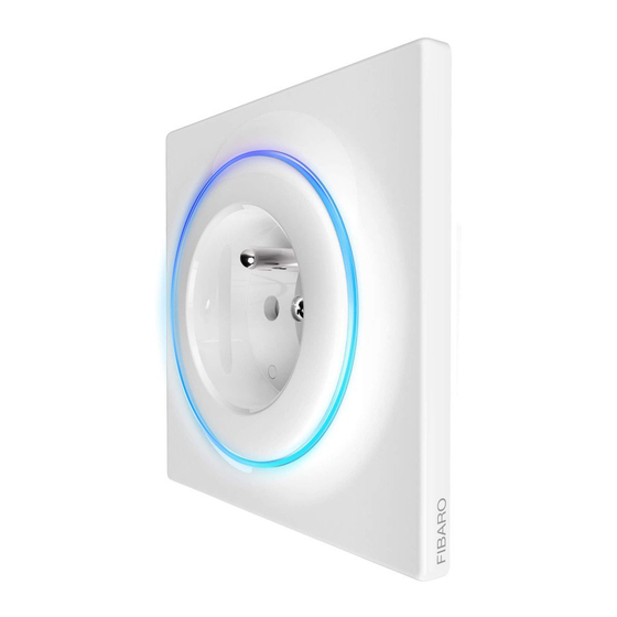
2: Description and features 2.1: Description FIBARO Walli Outlet is a smart electrical outlet designed to control electrical devices via Z-Wave network. It measures active power and energy consumed by the controlled load. You can install it with provided cover plate and socket cover or other compatible. -
Page 6: 3: Specifications
50m outdoors up to 40m indoors (depending on terrain and building structure) Dimensions FGWOE-011: 86 x 86 x 48 mm (Height x Width x Depth) FGWOF-011: 86 x 86 x 51 mm Compliance with EU RoHS 2011/65/EU directives... -
Page 7: 4: Installation
• Make sure you have all required parts when installing with covers other than FIBARO (see “Parts compatibility” on page 29). Device parts: 1 – screw, 2 – socket cover, 3 – cover plate, 4 – unit (device), 5 – mount- ing frame 4.2: Preparing for installation... -
Page 8: Electrical Connection
3. Verify correctness of connection. 4. Tighten the terminal screws using PH1 screwdriver. 4.4: First assembly When installing with FIBARO covers: 1. Insert the device with mounting frame into the mounting box and secure with mounting claws and screws. 2. Snap the cover plate to the device. -
Page 9: Changing Covers
4.5: Changing covers For safety reasons the button should be used only with FIBARO cover. We recommend adding the device to Z-Wave network before changing the cover plate. When installing with covers other than FIBARO, we recommend disabling the LED by changing parameter 13 to 0. - Page 10 4. Replace FIBARO mounting frame with Legrand mounting frame (FG-Wx-AS-4002). 5. Connect wires according to “Electrical connection” on page 8. 6. Insert the device with mounting frame into the mounting box and secure with mounting claws and screws. 7. Snap the new cover plate to the device.
-
Page 11: 5: Adding To Z-Wave Network
Full DSK code is present only on the box, make sure to keep it or copy the code. 5.1: Adding manually Use the button only with FIBARO cover to ensure safety. To add the device to the Z-Wave network manually: 1. Power the device. -
Page 12: Adding Using Smartstart
5.2: Adding using SmartStart SmartStart enabled products can be added into a Z-Wave network by scanning the Z-Wave QR Code present on the product with a con- troller providing SmartStart inclusion. SmartStart product will be added automatically within 10 minutes of being switched on in the network range. -
Page 13: 6: Removing From Z-Wave Network
6: Removing from Z-Wave network Use the button only with FIBARO cover to ensure safety. 1. Button, 2. LED ring. Removing (Exclusion) – Z-Wave device learning mode, allowing to remove the device from existing Z-Wave network. Removing also re- sults in resetting the device to factory defaults. -
Page 14: 7: Operating The Device
7: Operating the device 7.1: Controls 1. Button, 2. LED ring. Use the button only with FIBARO cover to ensure safety. 7.2: Button control • 1xClick – change to the opposite state (ON/OFF), • 3xClick – start learn mode to add/remove to/from Z-Wave network, •... -
Page 15: Menu
Certain device removal can be achieved by the procedure of removing described. Use the button only with FIBARO cover to ensure safety. 1. Press and hold the button to enter the menu. -
Page 16: 8: Power And Energy Metering
1kWh = 1000Wh. Resetting consumption memory: Use the button only with FIBARO cover to ensure safety. 1. Press and hold the button to enter the menu. 2. Release button when the device glows green. -
Page 17: 9: Z-Wave Range Test
9: Z-Wave range test The device has a built in Z-Wave network main controller’s range tester. To make Z-Wave range test possible, the device must be added to the Z-Wave controller. Testing may stress the network, so it is recommended to perform the test only in special cases. -
Page 18: 10: Configuration
The settings can be adjusted via the Z-Wave controller to which the device is added. The way of adjusting them might differ depending on the controller. In the FIBARO interface parameters are presented as simple options in the Advanced Settings of the device. Available parameters:... - Page 19 Overload safety switch This function allows to turn off the controlled device in case of ex- ceeding the defined power. Controlled device can be turned back on via button or sending a control frame. Parameter size 4B Default value 0 (disabled) 0 –...
- Page 20 LED frame – colour when OFF This parameter defines the LED colour when the device is OFF. Parameter size 1B Default value 0 (disabled) 0 – LED disabled 1 – White 2 – Red 3 – Green Available values 4 – Blue 5 –...
- Page 21 Alarm configuration - 1st slot This parameter determines to which alarm frames and how the device should react. The parameters consist of 4 bytes, three most significant bytes are set according to the official Z-Wave protocol specification. Parameter size 4B Default value [0x00, 0x00, 0x00, 0x00] (disabled) 1B [MSB] –...
- Page 22 Alarm configuration - 3rd slot This parameter determines to which alarm frames and how the device should react. The parameters consist of 4 bytes, three most significant bytes are set according to the official Z-Wave protocol specification. Parameter size 4B [0x01, 0xFF, 0x00, 0x00] Default value (Smoke Alarm, any notification, no action)
- Page 23 Alarm configuration - 5th slot This parameter determines to which alarm frames and how the device should react. The parameters consist of 4 bytes, three most significant bytes are set according to the official Z-Wave protocol specification. Parameter size 4B [0x04, 0xFF, 0x00, 0x00] Default value (Heat Alarm, any notification, no action)
- Page 24 Associations – UP threshold This parameter determines upper power threshold for 2nd associ- ation group (paramter 45). Exceeding it will result in sending value set in parameter 47. Cannot be lower than DOWN threshold (parameter 48). Parameter size 4B Default value 500 (50W) Available 100-36800 (10-3680W, 0.1W step) –...
- Page 25 Power reports – include self-consumption This parameter determines whether the power measurements should include power consumed by the device itself. Parameter size 1B Default value 0 (not included) 0 – Self-consumption not included Available values 1 – Self-consumption included Power reports – on change This parameter defines minimal change (from the last reported) in measured power that results in sending new report.
- Page 26 Energy reports – periodic This parameter defines reporting interval for measured energy. Periodic reports are independent from changes in value (parame- ter 65). Parameter size 2B Default value 3600 (1h) 0 – periodic reports disabled Available values 30-32400 (30s-9h, 1s step) – time interval CONFIGURATION...
-
Page 27: 11: Z-Wave Specification
11: Z-Wave specification Generic Device Class: GENERIC_TYPE_SWITCH_BINARY Specific Device Class: SPECIFIC_TYPE_POWER_SWITCH_BINARY Supported Command Classes Command Class Version Secure 1.COMMAND_CLASS_ZWAVEPLUS_INFO [0x5E] 2.COMMAND_CLASS_SWITCH_BINARY [0x25] 3.COMMAND_CLASS_ASSOCIATION [0x85] COMMAND_CLASS_MULTI_CHANNEL_ASSOCI- ATION [0x8E] COMMAND_CLASS_ASSOCIATION_GRP_INFO [0x59] COMMAND_CLASS_TRANSPORT_SERVICE [0x55] 7.COMMAND_CLASS_VERSION [0x86] COMMAND_CLASS_MANUFACTURER_SPECIFIC [0x72] COMMAND_CLASS_DEVICE_RESET_LOCALLY [0x5A] 10.COMMAND_CLASS_POWERLEVEL [0x73] 11.COMMAND_CLASS_SECURITY [0x98] 12.COMMAND_CLASS_SECURITY_2 [0x9F] 13.COMMAND_CLASS_METER [0x32] 14.COMMAND_CLASS_CONFIGURATION [0x70]... - Page 28 Notification Command Class The device uses Notification Command Class to report different events to the controller (“Lifeline” group). Notification Type Event Parameter Power Management Over-current detected [0x08] [0x06/V3] Power Management Over-load detected [0x08] [0x08/V3] System hardware fail- ure with manufactur- MP code: 0x01 System [0x09] er proprietary failure...
-
Page 29: 12: Parts Compatibility
12: Parts compatibility Available FIBARO parts Included Name Symbol FGWOF-011 FGWOE-011 Socket F Unit FG-WO-AS-4002 Socket E Unit FG-WO-AS-4003 Socket F FG-WO-PP-0010 Socket E FG-WO-PP-0009 Outer Lightguide FG-WO-PP-0004 Shutter Unit FG-WO-AS-4001 Mounting Frame FIBARO/ FG-Wx-AS-4001 GIRA Mounting Frame Legrand FG-Wx-AS-4002 Mounting Frame... - Page 30 Parts required for Schneider Odace covers Required FIBARO parts Socket type Schneider Schneider Name Symbol Type F Type E Socket F Unit FG-WO-AS-4002 Socket E Unit FG-WO-AS-4003 Mounting Frame FG-Wx-AS-4003 Schneider Shutter Unit FG-WO-AS-4001 PARTS COMPATIBILITY...
-
Page 31: 13: Regulations
FIBARO and Fibar Group logo are trademarks of Fibar Group S.A. All other brands and product names referred to herein are trademarks of their respective holders.
Need help?
Do you have a question about the FGWOE-011 and is the answer not in the manual?
Questions and answers