Subscribe to Our Youtube Channel
Summary of Contents for aFe Power F1-03003
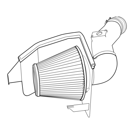
- Page 1 ® advanced FLOW engineering Instruction Manual P/N: F1-03003 Make: Ford Model: Super Duty Year: 03-07 Engine: V8-6.0L (td)
- Page 2 ® • Please read the entire instruction manual before proceeding. • Ensure all components listed are present. • If you are missing any of the components, call customer support at 951-493-7100. • Ensure you have all necessary tools before proceeding. •...
- Page 3 aFepower.com Page 3...
- Page 4 ® REMOVAL Figure A Refer to Figure A for steps 1-2 Step 1: Warning!! Do not disconnect the coolant reservoir hose if the engine is hot. Remove the (2) screws 1 securing the radiator reservoir then pull forward and upward to gain clearance.
- Page 5 REMOVAL Figure B Refer to Figure B for step 3-6 Step 3: Loosen clamps 1 at turbo & filter canister & remove canister. Step 4: Reach under the intake tube & disconnect the valve cover vent fitting. Step 5: Disconnect the filter minder wire harness 2 . Step 6: Pull the intake tube from vehicle.
- Page 6 ® INSTALL Figure C Refer to Figure C for steps 7-9 Step 7: Install the small and large grommets on to new intake tube H & I . Step 8: Transfer the mass air sensor & screws to the new tube. Step 9: Remove the valve cover vent hose &...
- Page 7 INSTALL Figure D Refer to Figure D for Step 10 Step 10: Preinstall the air diverter J into the 4” rubber 90-elbow coupling E . aFepower.com Page 7...
- Page 8 ® INSTALL Figure E Refer to Figure E for step 11 Step 11: Install the silicone coupling D onto the turbo. Place both large clamps in position but do not tighten at this time. Page 8...
- Page 9 INSTALL Figure F Refer to Figure F for step 12-14 Step 12: Install the new intake tube onto the turbo. Step 13: Connect vent hose to valve cover fitting using the small hose clamps. Step 14: Transfer the filter minder to the small grommet & connect wire harness. aFepower.com aFepower.com Page 9...
- Page 10 ® INSTALL Figure G Refer to Figure G for step 15 Step 15: Loosely place the (2) 064 clamps F onto the 4” coupler elbow Install the 4’ rubber elbow E with air diverter onto the intake tube. The long leg of the rubber elbow goes over the intake tube.
- Page 11 INSTALL Figure H Refer to Figure H for steps 16-17 Step 16: Drop the housing C into place & secure with the existing screw at the radiator bulkhead. Make sure the housing bottom tab engages in its slot. Step 17: The rubber elbow can be connected to the filter adapter & all clamps tightened. aFepower.com Page 11...
- Page 12 ® INSTALL Figure I Refer to Figure I for steps 17-19 Step 17: Attach edge trim C to the top edge of the filter housing. Step 18: Connect the mas sensor wire harness & install the air filter. Step 19: Position the coolant reservoir in its original location & tighten. Step 20: Tighten all clamps and retighten after approximately 150 miles.
- Page 13 Page left blank intentionally aFepower.com Page 13...
- Page 14 ® aFe Key Chain Pro DRY S Air Filter Pro DRY S Restore Kit aFe Power Hat P/N: 21-90032 P/N: 90-59999 P/N: 40-10083 P/N: 40-10103 To purchase any of the items above, view airflow charts, dyno graphs, photos, and video; please go to aFepower.com.
-
Page 15: Warranty
Warranty aFe warrants their intake systems to be free of defects from workmanship and materials for a period of two (2) years, provided the intake system was: A) installed in an aFe recommended application according to aFe installation instructions; and B) the air filter has been properly cleaned utilizing an aFe cleaning solution and oil (not applicable on Pro DRY S filters). - Page 16 ® ® advanced FLOW engineering, inc. 252 Granite Street Corona, CA 92879 TEL: 951.493.7100 • TECH: 951.493.7100 x23 E-Mail:Tech@aFepower.com P/N: 06-80376...


Need help?
Do you have a question about the F1-03003 and is the answer not in the manual?
Questions and answers