Advertisement
Quick Links
NCN5100 Arduinot Shield
Evaluation Board
User's Manual
EVBUM2715/D
INTRODUCTION
KNX [3] is a popular open home and building automation standard
ON Semiconductor has a series of transceivers that handle the low
level communication.
The NCN5100ASGEVB evaluation boards are Arduino-compatible
shields enabling rapid prototyping with a microcontroller of choice.
All external components necessary for operating the transceivers are
present on the shield. Plug it in a Arduino-compatible development kit
and start developing!
FEATURES
•
Arduino Uno V3 compatible connectors
Compatible with a wide variety of microcontroller development
♦
boards
•
Four on-board buttons/LEDs to build a dimmer application
•
Available in UART- and SPI-version
Fully KNX-compliant transceiver
♦
•
Easily get started with KNX
•
Maximum bus current up to 40 mA
•
Two high-efficiency DC-DC converters
3.3 V fixed output
♦
1.2 V to 21 V variable output
♦
•
Integrated 20 V linear regulator output
OVERVIEW
The NCN5100ASGEVB boards come in three variants containing
the NCN5110, NCN5121 and NCN5130 transceivers. The NCN5110
is a bit transceiver and all the timings are handled by the
microcontroller. Both the NCN5121 and NCN5130 also implement
the MAC layer, reducing the software development effort. All critical
timings are handled by the transceiver.
All transceivers include two high-effciency DC-DC converters. One
fixed converter generating 3.3 V, supplies the transceiver and other
optional peripherals such as a microcontroller. The second DC-DC
converter has an adjustable output voltage ranging from 1.2 V to 21 V
and can be used to supply peripherals such as, relays, a display, etc. ...
The Arduino shield form factor makes it easy to start developing;
just plug the shield into a compatible microcontroller board and start
coding. Thanks to the on-board buttons and LEDs, it is not necessary
to plug in additional shields to start testing. A simple dimmer
application can be set-up in no time with only the KNX
Arduino-shield.
1
https://my.knx.org
2
For the NCN5130 and NCN5110 version. The NCN5121 goes up to 24 mA.
© Semiconductor Components Industries, LLC, 2020
October, 2020 − Rev. 2
2
1
www.onsemi.com
1
.
EVAL BOARD USER'S MANUAL
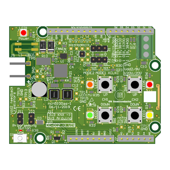
Figure 1. NCN5100AS-1 Evaluation Board
Figure 2. NCN5100AS-2 Evaluation Board
Publication Order Number:
EVBUM2715/D
Advertisement

Subscribe to Our Youtube Channel
Related Manuals for ON Semiconductor Arduino NCN5100


Summary of Contents for ON Semiconductor Arduino NCN5100
- Page 1 EVBUM2715/D INTRODUCTION www.onsemi.com KNX [3] is a popular open home and building automation standard ON Semiconductor has a series of transceivers that handle the low EVAL BOARD USER’S MANUAL level communication. The NCN5100ASGEVB evaluation boards are Arduino-compatible shields enabling rapid prototyping with a microcontroller of choice.
-
Page 2: Evaluation Board Overview
All the EVALUATION BOARD OVERVIEW ON Semiconductor KNX transceivers contain a built-in The main connectivity to the evaluation board is provided mechanism to keep the draw within the value specified in its through the Arduino V3 headers which can be seen in datasheet. - Page 3 EVBUM2715/D A list of recommended fan-in resistor values can be found Power The board is powered through the KNX-connector. These in Table 1. For the listed resistor values, the corresponding two pins (KNX+/KNX- in Figure 9) mate with a typical current limits are specified in the datasheet.
- Page 4 EVBUM2715/D To avoid this situation a transistor is added in series with Powering External Circuitry the NRST-line as shown in Figure 8. If the 3.3 V from the The transceiver’s 20 V LDO and DC-DC2 converter can KNX transceiver is absent, the transistor does not conduct, be used to power additional circuitry, e.g.
- Page 5 EVBUM2715/D Or use the KNX Family Efficiency Calculator which can Arduino NCN5100 evalutation board be found on the ON Semiconductor website. Inputs and Outputs Arduino Header Pin-Out NRST Debugger Most of the buttons and LEDs are connected to digital pins on the Arduino headers.
- Page 6 EVBUM2715/D User Buttons and LEDs when the transceiver operates in SPI-mode it acts as the The shield has 4 on-board push buttons (SW1...4) and master. The microcontroller must support slave mode in 4 LEDs (LED2...5) to enable the development of switching order to be able to communicate with the transceiver.
-
Page 7: Pcb Layout Guidelines
EVBUM2715/D Selecting The Baud Rate Enable Interface Jumpers J1 and J2 allow easy configuration of the baud The timing of the pulses which drive the NCN5110 are rate and parity. This is only used in UART-mode. In extremely time critical. Some microcontroller families have SPI-mode, the communication speed is fixed to 500 kbps. - Page 8 EVBUM2715/D Single−layer design Single−layer optimized Signal Signal Return Return Figure 14. Optimizing the Return Path in a Single-layer Design Dual−layer design Dual−layer optimized Signal Signal Return Return Figure 15. Optimizing the Return Path in a Dual-layer Design where there is a slot in the ground plane. The return path now Inverter Load goes around the slot creating a slot antenna.
-
Page 9: Getting Started
EVBUM2715/D The larger buffer capacitor C9 can be placed further away from the VIN-pin, as long as the small ceramic capacitor C8 is placed very close to it. KNX+ KNX* To VBUS Cpar Figure 17. Schematic Showing the DC-DC Converter Current Loops Figure 19. - Page 10 EVBUM2715/D Prerequisites To meet the timing requirements to communicate on the Listed below are all the components needed to construct KNX-bus, it is mandatory to have a more accurate clock than a small KNX-network with the NCN5100ASGEVB. the on provided by the internal RC-oscillator of the •...
- Page 11 Installing The Software The microcontroller demo software can be found on the ON Semiconductor website [5]. Download the software, unpack it and execute the installer. The installer will first ask in which folders to install the software.
- Page 12 EVBUM2715/D KEIL mVision IDE. The necessary files are located in the workspace folder. For more information refer to the documentation included with the installation. Lastly there are two batch files included in the folder. These can be used to build and rebuild the application. To get started with the previously built setup, one of the example projects must be loaded in the microcontroller.
- Page 13 EVBUM2715/D Figure 31. Import the ETS-project Included with the Demo Application A room can not exist on it’s own and must be created inside a building. To create a building, click on the word Buildings and then Add Buildings. Once the building is created, right click on it and select Add →...
- Page 14 EVBUM2715/D Now the group addresses have to be assigned in order for It is possible to review and adjust the group the device to communicate on the bus. Refer to the official addresses/names in the Group Addresses panel (Workplace → Open New Panel). KNX-documentation [4] for more information on how the communication system with group addresses works.
- Page 15 EVBUM2715/D ETS will now ask to press the programming button on the on the bus with the value On. LED3 on the shield should now NCN5100ASGEVB. It can be found on the lower left corner light up. When pressing the Read button again the device of the shield.
- Page 16 EVBUM2715/D APPENDIX B − MICROCONTROLLER NET LIST NCN5100AS-2 Table 5. MICROCONTROLLER PINS LIST Pin Arduino Headers Connected to Function MCU Pin Direction D3/PWM LED5 CH2 Red up button LED Up button CH2 D5/PWM LED3 CH2 Yellow down button LED D6/PWM LED2 CH1 Green down button LED Down button CH1...
- Page 17 EVBUM2715/D APPENDIX C − LIST OF TESTED PLATFORMS Table 6. TESTED PLATFORMS Manufacturer Development Board Microcontroller STMicroelectronics NUCLEO−F103RB STM32F103RB Cypress CY8CKIT−044 CY8C4247AZI−M485 Waveshare XNUCLEO−F103RB STM32F103RB www.onsemi.com...
- Page 18 EVBUM2715/D APPENDIX D − NCN5130ASGEVB UART-version Figure 38. Schematic www.onsemi.com...
- Page 19 EVBUM2715/D Table 7. BILL OF MATERIALS UART-VERSION Designator Description Value Part Number WR−PHD 2.54 mm THT Pin Header, 3p 61300311121 WR−PHD 2.54 mm THT Pin Header, 3p 61300311121 WR−PHD 2.54 mm THT Pin Header, 1p 61300111121 Board-To-Board Connector, 2.54 mm, SSQ−110−03−G−S 8 Contacts, Receptacle, Through Hole, 1 Rows Board-To-Board Connector, 2.54 mm,...
- Page 20 EVBUM2715/D Table 7. BILL OF MATERIALS UART-VERSION (continued) Designator Description Value Part Number SMAJ40CA − TVS Diode, TRANSZORB SMAJ 40 V, 400 W SMAJ40CA Series, Bidirectional, 40 V, 64.5 V, DO−214AC, 2 Pins Capacitor 47 nF, 50 V CGA3E2X7R1H473K080AA Capacitor 100 mF, 35 V EEEFT1V101AP 6.0 x 3.8 mm SMD J−Bend WS−TASV...
- Page 21 EVBUM2715/D SPI-version Figure 39. Schematic www.onsemi.com...
- Page 22 EVBUM2715/D Table 8. BILL OF MATERIALS SPI-VERSION Designator Description Value Part Number WR−PHD 2.54 mm THT Pin Header, 1p 61300111121 Board-To-Board Connector, 2.54 mm, SSQ−110−03−G−S 8 Contacts, Receptacle, Through Hole, 1 Rows Board-To-Board Connector, 2.54 mm, SSQ−110−03−G−S 10 Contacts, Receptacle, Through Hole, 1 Rows Board-To-Board Connector, 2.54 mm, SSQ−106−03−G−S...
- Page 23 EVBUM2715/D Table 8. BILL OF MATERIALS SPI-VERSION (continued) Designator Description Value Part Number Capacitor 100 mF, 35 V EEEFT1V101AP 6.0 x 3.8 mm SMD J−Bend WS−TASV 100 mW, 250 V (AC) 434 123 025 816 C3, C4 Capacitor 100 nF CC0402KRX7R7BB104 Capacitor 100 nF, 50 V...
- Page 24 EVBUM2715/D APPENDIX E − NCN5121ASGEVB UART-version Figure 40. Schematic www.onsemi.com...
- Page 25 EVBUM2715/D Table 9. BILL OF MATERIALS UART-VERSION Designator Description Value Part Number WR−PHD 2.54 mm THT Pin Header, 3p 61300311121 WR−PHD 2.54 mm THT Pin Header, 3p 61300311121 WR−PHD 2.54 mm THT Pin Header, 1p 61300111121 Board-To-Board Connector, 2.54 mm, SSQ−110−03−G−S 8 Contacts, Receptacle, Through Hole, 1 Rows Board-To-Board Connector, 2.54 mm,...
- Page 26 EVBUM2715/D Table 9. BILL OF MATERIALS UART-VERSION (continued) Designator Description Value Part Number SMAJ40CA − TVS Diode, TRANSZORB SMAJ 40 V, 400 W SMAJ40CA Series, Bidirectional, 40 V, 64.5 V, DO−214AC, 2 Pins Capacitor 47 nF, 50 V CGA3E2X7R1H473K080AA Capacitor 100 mF, 35 V EEEFT1V101AP 6.0 x 3.8 mm SMD J−Bend WS−TASV...
- Page 27 EVBUM2715/D SPI-version Figure 41. Schematic www.onsemi.com...
- Page 28 EVBUM2715/D Table 10. BILL OF MATERIALS SPI-VERSION Designator Description Value Part Number WR−PHD 2.54 mm THT Pin Header, 1p 61300111121 Board-To-Board Connector, 2.54 mm, SSQ−110−03−G−S 8 Contacts, Receptacle, Through Hole, 1 Rows Board-To-Board Connector, 2.54 mm, SSQ−110−03−G−S 10 Contacts, Receptacle, Through Hole, 1 Rows Board-To-Board Connector, 2.54 mm, SSQ−106−03−G−S...
- Page 29 EVBUM2715/D Table 10. BILL OF MATERIALS SPI-VERSION (continued) Designator Description Value Part Number Capacitor 100 mF, 35 V EEEFT1V101AP 6.0 x 3.8 mm SMD J−Bend WS−TASV 100 mW, 250 V (AC) 434 123 025 816 C3, C4 Capacitor 100 nF CC0402KRX7R7BB104 Capacitor 100 nF, 50 V...
- Page 30 EVBUM2715/D APPENDIX F − NCN5110ASGEVB SCHEMATIC (FULL OPTION) Full Option Figure 42. Schematic www.onsemi.com...
- Page 31 EVBUM2715/D Table 11. BILL OF MATERIALS FULL VERSION Designator Description Value Part Number WR−PHD 2.54 mm THT Pin Header, 03p 61300311121 Board-To-Board Connector, 2.54 mm, SSQ−110−03−G−S 8 Contacts, Receptacle, Through Hole, 1 Rows Board-To-Board Connector, 2.54 mm, SSQ−110−03−G−S 10 Contacts, Receptacle, Through Hole, 1 Rows Board-To-Board Connector, 2.54 mm, SSQ−106−03−G−S...
- Page 32 EVBUM2715/D Table 11. BILL OF MATERIALS FULL VERSION (continued) Designator Description Value Part Number Capacitor 100 nF, 50 V Capacitor 100 nF, 16 V Capacitor 100 nF, 50 V Resistor 130 W Capacitor 220 nF, 50 V R1, R4, R5, R34 Resistor 560 W LED6...
- Page 33 EVBUM2715/D Minimal BoM Version Figure 43. Schematic www.onsemi.com...
- Page 34 EVBUM2715/D Table 12. BILL OF MATERIALS minimal BOM VERSION Designator Description Value Part Number WR−PHD 2.54 mm THT Pin Header, 03p 61300311121 Board-To-Board Connector, 2.54 mm, SSQ−110−03−G−S 8 Contacts, Receptacle, Through Hole, 1 Rows Board-To-Board Connector, 2.54 mm, SSQ−110−03−G−S 10 Contacts, Receptacle, Through Hole, 1 Rows Board-To-Board Connector, 2.54 mm, SSQ−106−03−G−S...
- Page 35 EVBUM2715/D Table 12. BILL OF MATERIALS minimal BOM VERSION (continued) Designator Description Value Part Number LED6 Surface Mount Chip LED, Red 0603, Red KPT−1608EC R33, R38 Resistor 680 W R14, R35, R36 Resistor 750 W LED1, LED5 LED, Red, 2.4 mm, 636 nm, 1.8 V, 2 mA, Led, Red, 1.8 V, 2 mA VLMS30J1L2−GS08 18 mcd...
- Page 36 onsemi, , and other names, marks, and brands are registered and/or common law trademarks of Semiconductor Components Industries, LLC dba “onsemi” or its affiliates and/or subsidiaries in the United States and/or other countries. onsemi owns the rights to a number of patents, trademarks, copyrights, trade secrets, and other intellectual property. A listing of onsemi’s product/patent coverage may be accessed at www.onsemi.com/site/pdf/Patent−Marking.pdf.
Need help?
Do you have a question about the Arduino NCN5100 and is the answer not in the manual?
Questions and answers