Table of Contents
Advertisement
Quick Links
NCV73830V1GEVB
NCV7383 FlexRay
Driver Evaluation Board
User's Manual
Introduction
This document describes the NCV7383EVB Evaluation
board for the ON Semiconductor NCV7383 FlexRay Bus
Driver. The functionality and major parameters can be
evaluated with the NCV7383EVB board.
The NCV7383 is a single-channel FlexRay bus driver
compliant with the FlexRay Electrical Physical Layer
Specification Version 3.0.1, capable of communicating at
speeds of up to 10 Mb/s. It provides differential transmit and
receive capability between a wired FlexRay communication
medium on one side and a protocol controller and a host on
the other side.
NCV7383 mode control functionality is optimized for
nodes without the need of extended power management
provided by transceivers with permanent connection to the
car battery as is on NCV7381.
NCV7383 is primarily intended for nodes switched off by
ignition. Additional details can be found in the NCV7383
datasheet.
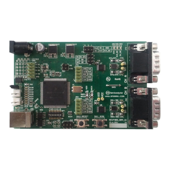
Figure 1. Evaluation Board Photo
The NCV7383EVB Evaluation board is a reference
design for stand-alone 2−channel FlexRay node. The board
is intended to give designers easy, quick and convenient
means for evaluation of NCV7383 FlexRay bus drivers. The
design incorporates complete node solution with possibility
of modifications and small board size. A set of two boards
© Semiconductor Components Industries, LLC, 2013
July, 2013 − Rev. 1
Arrow.com.
Downloaded from
)
Bus
allows users immediately start with the NCV7383 FlexRay
Bus Driver. The MCU is preprogrammed with a firmware
which provides simple mode control and FlexRay
communication. With use of Freescalet BDM programmer
and a suitable development environment, the MCU
firmware can be freely modified and reprogrammed.
V
IO
TxD
TxEN
RxD
BGE
STBN
SCK
Board Hardware
The board consists of MCU with integrated 2-channel
FlexRay communication controller interconnected with two
separate FlexRay bus drivers (NCV7383), two voltage
regulators and peripherals. The board is prepared for various
modifications in power supply concept and FlexRay bus
termination, and allows simple extension of the system by
unused MCU pins. USB interface provides compatibility
with standard PC. The address of each board can be easily
modified by address switch what allows to create complex
FlexRay network without the need of reprogramming the
MCU. Implemented High Speed CAN interface can be used
as a diagnostic interface in a network built from several
nodes. For evaluation purposes NCV7383 is populated with
several LED diodes and most of the bus driver signals are
comfortable accessible to oscilloscope probes.
1
http://onsemi.com
EVAL BOARD USER'S MANUAL
1
Figure 2. NCV7383 Pin Connections
Publication Order Number:
V
CC
BP
BM
GND
ERRN
CSN
SDO
EVBUM2172/D
Advertisement
Table of Contents

Related Manuals for ON Semiconductor NCV73830V1GEVB


Summary of Contents for ON Semiconductor NCV73830V1GEVB
- Page 1 User's Manual Introduction http://onsemi.com This document describes the NCV7383EVB Evaluation board for the ON Semiconductor NCV7383 FlexRay Bus EVAL BOARD USER’S MANUAL Driver. The functionality and major parameters can be evaluated with the NCV7383EVB board. The NCV7383 is a single-channel FlexRay bus driver...
-
Page 2: General Features
NCV73830V1GEVB GENERAL FEATURES FlexRay Transceiver • All NCV7383 digital I/O pins connected to test points – • Two separate FlexRay channels with NCV7383 Bus easy connection to Logic Analyzer Driver compliant with the FlexRay Electrical Physical • 8 general purpose LEDs Layer Specification Version 3.0.1,... - Page 3 NCV73830V1GEVB Figure 3. Basic NCV7383 Evaluation Board connection Power Modes Normal Mode LED Signaling The nodes can operate in two different power modes: The properly running setup should signal following • (Figure 4): Normal mode – all the nodes continuously communicates over the FlexRay bus.
- Page 4 NCV73830V1GEVB ⋅ Battery voltage being below 10 V is indicated by Standby Mode LED Signaling In Standby mode, all the LEDs except LED8 are switched LED1 OFF state. OFF. The LED8 is turned ON with very low intensity, ⋅ Battery voltage exceeding 14 V is indicated by signaling the MCU is correctly operating in the low power LED1 full intensity (Figure 5).
-
Page 5: Board Overview
NCV73830V1GEVB BOARD OVERVIEW Basic Interface Figure 7. NCV7383EVB Connectors and Switches Legend: 9. BDM Connector (MCU debugging interface) 1. Power supply input connector 10. Power supply input connector 2. Aux digital I/O connector 11. Aux digital I/O connector 3. CAN backbone connector 1 12. - Page 6 NCV73830V1GEVB connectors in parallel, so whole network can be prepared FlexRay BD Digital Signals Test Points Headers These headers are intended to be used as a test points for using only simple point-to-point twisted pair. digital probes. Headers contain all FlexRay BD digital input and output signals.
- Page 7 NCV73830V1GEVB Jumpers and Default Configuration Figure 14. Jumpers and Soldering Straps Table 2. 2−PIN JUMPER Table 3. 3−PIN JUMPER Open 1 2 3 Open Closed Closed position 1−2 Closed position 2−3 http://onsemi.com Arrow.com. Downloaded from...
- Page 8 NCV73830V1GEVB Table 4. NCV7383 EVB JUMPERS CONFIGURATION Jumper Function Configuration Description Default Bus Driver VIO supply Closed Open Bus Driver VIO unsupplied 3V3 – 3V3_BD Closed Bus Driver VIO connected to voltage regulator output Bus Driver VCC supply Open Bus Driver VCC unsupplied Closed 5V –...
- Page 9 NCV73830V1GEVB FlexRay Bus Driver Figure 16. FlexRay Bus Termination Connection (Channel A: R7x, C7x; Channel B: R8x, C8x) Table 5. FLEXRAY BUS TERMINATION CONFIGURATION AND PARAMETERS End node Middle node – Variant 1 Middle node – Variant 2 Component (Low-Ohmic termination)
- Page 10 NCV73830V1GEVB Address Switch ⋅ The switch configuration shown in this figure This switch is used for setting a node number. Each board means binary 0b00000010 (Node address is set is programmed with the same firmware, so every node in the to 2).
-
Page 11: Block Diagram
NCV73830V1GEVB BLOCK DIAGRAM PROGRAMMING/ SWITCHES DEBUG INTERFACE INTERFACE BACKBONE CLOCK LED’s EXTERNAL MC9S12XF512MLM AUX I/O PINS RESET FlexRay CC POWER SUPPLIES AUX OUTPUTS FlexRay CC A FlexRay CC B MCU & FR BD IO VIO 3V3 FR BD VCC NCV7383... -
Page 12: Specifications
NCV73830V1GEVB Table 6. RECOMMENDED EXTERNAL COMPONENTS FOR THE APPLICATION DIAGRAM Component Function Min. Typ. Max. Unit Note Decoupling capacitor on V supply line, ceramic Decoupling capacitor on V supply line, ceramic Bus termination resistor 47.5 BUS1 Bus termination resistor 47.5... - Page 13 NCV73830V1GEVB Table 8. BASIC SPLIT TERMINATION PARAMETERS Value End node Middle node Name Description Units Termination resistors 1300 Capacitor 4700 4700 Custom Termination In some cases a specific termination topology is required FlexRay Bus Driver for middle modes. Such a termination connection and typical values are shown in Figure 25 and Table 9.
- Page 14 NCV73830V1GEVB Table 10. COMMON−MODE CHOKE REQUIREMENTS [2] Name Description Units Resistance per line ≤ 1 Main inductance ≥ 100 Stray inductance < 1 MCU PROGRAMMING INTERFACE NCV7383 firmware freely reprogrammed using MCU programming and debugging interface (J10). The used Freescale MC9S12XF Family MCU can be programmed with P&E USB Multilink BDM...
- Page 15 NCV73830V1GEVB Figure 28. Freescale CodeWarrior Development Tool The NCV7383 EVB firmware can be downloaded from ON Semiconductor web site (www.onsemi.com). http://onsemi.com Arrow.com. Downloaded from...
- Page 16 NCV73830V1GEVB SCHEMATIC http://onsemi.com Arrow.com. Downloaded from...
-
Page 17: Pcb Drawings
NCV73830V1GEVB PCB DRAWINGS Assembly Drawings Figure 29. NCV7383 EVB PCB Top Assembly Drawing Figure 30. NCV7383 EVB PCB Bottom Assembly Drawing http://onsemi.com Arrow.com. Downloaded from... - Page 18 NCV73830V1GEVB Assembly Drawings Figure 31. NCV7383 EVB PCB Top Composite Drawing Figure 32. NCV7383 EVB PCB Bottom Composite Drawing (Mirrored) PCB General Parameters Dimensions • • Material: FR4 Length: 107.2 mm | 4220 mil • • Cu Plating Thickness: 18 mm | 0.5 oz Width: 70.4 mm | 2770 mil...
- Page 19 NCV73830V1GEVB REFERENCES [1] ON Semiconductor, NCV7383 FlexRay Bus Driver − Product Datasheet, Rev.0, January 2013 [2] FlexRay Consortium. FlexRay Communication System − Electrical Physical Layer Specification, V3.0.1, October 2010 [3] FlexRay Consortium. FlexRay Communication System − Physical Layer EMC Measurement Specification, V3.0.1, October 2010 All brand names and product names appearing in this document are registered trademarks or trademarks of their respective holders.
- Page 20 onsemi, , and other names, marks, and brands are registered and/or common law trademarks of Semiconductor Components Industries, LLC dba “onsemi” or its affiliates and/or subsidiaries in the United States and/or other countries. onsemi owns the rights to a number of patents, trademarks, copyrights, trade secrets, and other intellectual property. A listing of onsemi’s product/patent coverage may be accessed at www.onsemi.com/site/pdf/Patent−Marking.pdf.
Need help?
Do you have a question about the NCV73830V1GEVB and is the answer not in the manual?
Questions and answers