Advertisement
Quick Links
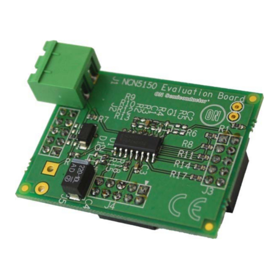
NCN5150NGEVB
NCN5150 Evaluation Board
User's Manual
Introduction
The NCN5150SOICGEVB and NCN5150QFNGEVB
evaluation boards demonstrate the NCN5150 M-BUS
transceiver in SOIC and QFN package respectively. These
evaluation boards include all external components needed
for operating NCN5150 and demonstrate the small PCB
surface area such an implementation requires.
Overview
The NCN5150 is a single-chip integrated slave
transceiver for use in two-wire Meter Bus (M-BUS) slave
devices and repeaters. The transceiver provides all of the
functions needed to satisfy the European Standards EN
13757−2 and EN 1434−3 describing the physical layer
requirements for M-BUS. It includes a programmable
power level of up to 2 (SOIC version) or 6 (NQFP version)
unit loads, which are available for use in external circuits
through a 3.3 V LDO regulator. The NCN5150 can provide
communication
up
to
communication speed of 38,400 baud (half-duplex).
Applications
Multi-energy Utility Meters
•
Water
•
Gas
•
Electricity
•
Heating Systems
Features
•
Single-chip MBUS Transceiver
•
UART Communication Speeds Up to 38,400 baud
© Semiconductor Components Industries, LLC, 2013
March, 2013 − Rev. 0
the
maximum
M-BUS
Figure 1. The NCN5150NGEVB Evaluation Boards
EVAL BOARD USER'S MANUAL
•
Integrated 3.3 V VDD LDO Regulator with Extended
Peak Current
•
Capability of 15 mA
•
Supports Powering Slave Device from the Bus or from
External Power Supply
•
Adjustable I/O Levels
•
Adjustable Constant Current Sink up to 2 or 6 Unit
Loads Depending on the Package
•
Low Bus Voltage Operation
•
Extended Current Budget for External Circuits:
minimum 0.8 mA
•
Polarity Independent
•
Power-Fail Function
•
Fast Startup − No External Transistor Required on STC
Pin
•
Industrial Ambient Temperature Range of −40°C to
+85°C
•
Available in:
16-pin SOIC (Pin-to-Pin Compatible with
♦
TSS721A)
20-pin QFN
♦
•
These are Pb-free Devices
1
http://onsemi.com
Publication Order Number:
EVBUM2178/D
Advertisement

Subscribe to Our Youtube Channel
Related Manuals for ON Semiconductor NCN5150SOICGEVB


Summary of Contents for ON Semiconductor NCN5150SOICGEVB
- Page 1 NCN5150NGEVB NCN5150 Evaluation Board User's Manual Introduction The NCN5150SOICGEVB and NCN5150QFNGEVB evaluation boards demonstrate the NCN5150 M-BUS http://onsemi.com transceiver in SOIC and QFN package respectively. These evaluation boards include all external components needed EVAL BOARD USER’S MANUAL for operating NCN5150 and demonstrate the small PCB surface area such an implementation requires.
-
Page 2: Electrical Characteristics
NCN5150NGEVB ELECTRICAL CHARACTERISTICS Table 1. ELECTRICAL CHARACTERISTICS OF THE NCN5150SOICGEVB AND NCN5150QFNGEVB BOARD Value Symbol Parameter / Condition Unit Bus Voltage Bus Voltage Current Drawn from the Bus 1 UL Output Voltage LDO output NCN5150 DESCRIPTION The NCN5150 provide a complete transceiver for the connected through a 0R resistor to 3.3 V on the evaluation... - Page 3 NCN5150NGEVB BOM List Table 2. NCN5150SOICGEVB BILL OF MATERIALS Quantity Reference Part Footprint Comments Manufacturer Product Code C0603 Multicomp MCCA000515 C0603 − − R3, R5, R9, R12, R0603 − − 100n C0603 50 V Multicomp MCCA000256 220u Case E 10 V...
- Page 4 NCN5150NGEVB Schematic Diagram Figure 3. Schematic of NCN5150SOICGEVB http://onsemi.com...
- Page 5 MCCA000256 220u Case E 10 V TAJD227K010RNJ Case E − − D1, D2, D4, D5 SOD−123 − − 1SMA40CAT3G ON Semiconductor 1SMA40CAT3G J1, J3, J4, J5 CON10A IMO Precision 21.95MH/2 J2, J6 CON2 Multicomp 2214S−10SG−85 Q1, Q2 SOT−23 − −...
- Page 6 NCN5150NGEVB Schematic Diagram Figure 5. Schematic of NCN5150QFNGEVB http://onsemi.com...
-
Page 7: Functional Description
NCN5150NGEVB FUNCTIONAL DESCRIPTION Power Supply Table 4. UL, RIDD VALUES, STC CAPACITANCE The NCN5150 provides power to be used in the Number of RIDD Maximum STC Min. Avail- application. To do this, the NCN5150 draws a fixed current Unit Loads Value Capacitor Value able Current... - Page 8 NCN5150NGEVB Figure 7. NCN5150 Shutdown Sequence UART Interface IDC1 The interface between the transceiver and an external microcontroller is a standard uart interface consisting of the TX and RX. Alternatively, inverted signals, TXI and RXI, which are active high, are also available. Only one signal from TX and TXI, or from RX and RXI can be used at the same time.
- Page 9 NCN5150NGEVB APPENDIX Evaluation Board Layout Figure 10. Top Layer Layout (SOIC) Figure 11. Bottom Layer Layout (SOIC) http://onsemi.com...
- Page 10 NCN5150NGEVB Figure 12. Top Layer Layout (QFN) Figure 13. Bottom Layer Layout (QFN) http://onsemi.com...
- Page 11 PUBLICATION ORDERING INFORMATION LITERATURE FULFILLMENT: N. American Technical Support: 800−282−9855 Toll Free ON Semiconductor Website: www.onsemi.com Literature Distribution Center for ON Semiconductor USA/Canada Order Literature: http://www.onsemi.com/orderlit P.O. Box 5163, Denver, Colorado 80217 USA Europe, Middle East and Africa Technical Support: Phone: 303−675−2175 or 800−344−3860 Toll Free USA/Canada...
- Page 12 Mouser Electronics Authorized Distributor Click to View Pricing, Inventory, Delivery & Lifecycle Information: ON Semiconductor NCN5150SOICGEVB...
Need help?
Do you have a question about the NCN5150SOICGEVB and is the answer not in the manual?
Questions and answers