
Related Manuals for Cole Parmer RV-400A-20


Summary of Contents for Cole Parmer RV-400A-20
- Page 1 ® Cole-Parmer RV-400 Series (10,20,50) ROTARY EVAPORATORS Instruction Manual 52411_10 20 50L Rotary Evaporator_ver_1.0 Applicable 20230V a.c. models only www.coleparmer.com...
-
Page 2: User Warning
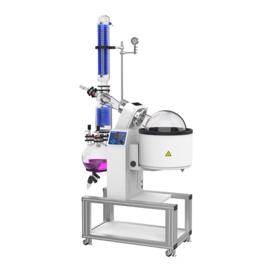
User Warning WARNING Failure to follow all warning and instructions could result in serious injury. Your safety is very important to us, we urge you to take the following precautions when using this product. We are not responsible for injury or damage caused by misuse. •... - Page 3 Purpose Rotary Evaporators are used to distill solvents from compounds with precise evaporation. These are especially useful when trying to separate organic compounds from ethanol, or any other low boiling point solvents. Boiling points can be lowered by pulling a vacuum on the system. The evaporating flask rotates with variable speeds, allowing you to spin the solution into a thin film around the flask.
- Page 4 Connecting the unit to the main supply This unit is supplied with an un-terminated mains cord. Connection to the supply must be made in accordance with local regulations THIS OPERATION SHOULD ONLY BE UNDERTAKEN BY A QUALIFIED ELECTRICIAN NOTE: Refer to the unit rating plate to ensure that the supply is suitable for the product cable wiring is colored as follows: UK / EU / US...
- Page 5 Technical Specifications RV-400A-10 RV-400A-20 RV-400A-50 Model 52411-98 52411-99 52410-00 20 ~130 rpm 20 ~ 110 rpm Rotational Speed RT+5°C ~ 85°C / RT+5°C ~ 99°C / RT+41°F ~ 210°F Bath Temp Range RT+41°F ~ 185°F Speed Setting Knob Setting + LCD Controller...
- Page 6 Breaker information Located on back of unit Cable/plug (US) Cable/plug (EU) Model Black – Live Brown – Live Fuse number White – Neutral Blue – Neutral Green - Earth Green/Yellow - Earth 52411-98 12AWG 2.5mm²/H05VV-F 16A Breaker 52411-99 12AWG 2.5mm²/H05VV-F 20A Breaker 52410-00 12AWG...
- Page 7 Main Components Diagram ⑴ ⑾ ⑵ ⑿ Be careful! Beware of the ⒀ ⑶ ⒁ hand! ⑷ ⒃ ⒂ ⑸ ⑹ ⑺ ⒄ ⒅ ⑻ ⒆ ⑼ ⒇ ⑽ (21) (22) Figure 1 1. Main Condenser 9. Receiving Flask 16. Evaporating Flask 2.
- Page 8 Main Condenser Structure Diagram: Vacuum Port Main Condenser Inlet Main Condenser Outlet Auxiliary Condenser Joint Figure 2 Bump Trap Structure Diagram: Auxiliary Condenser Joint Feed Port Joint Machine Head Joint Figure 3 Auxiliary Condenser Structure Diagram: Main condenser joint Auxiliary Condenser Inlet Joint Bump Trap Joint Auxiliary Condenser Outlet Joint Receiving Flask Joint...
- Page 9 Operating Panel Diagram Commented [HDA1]: Change to CP branded facia (12) (8) (9) (10) (11) Figure 6 REV: As the Evaporating Flask is rotating, this will display the revolutions per minute. TEMP: Displays the current temperature in degrees Celsius. RUN: Indicates when in heating or rotating status. Heating indicator: Arrows appear when the heating function is operating REV SET: Indicates the manually set speed in revolutions per minute.
- Page 10 Operation Panel Instructions Powering the unit: Plug in the power cord and press the on/off switch on the lower left side of body. When the rotary evaporator is on: 1. After the controller is powered on, it performs a self-test where all the values are displayed. This is a standard state.
- Page 11 Operation of over-temperature protector Over-temperature protector is an independent protective system. When temperature is out of control due to failure of the controller or the temperature in the working room reaches the set value for temperature limit on the over-temperature dial, the protector will cut off heating automatically and give an alarm sound.
- Page 12 Mounting Pole Diagram ⑻ Main Condenser Support Assembly Mounting Pole ⑴ Pole Union Auxiliary Condenser Support Assembly Receiving Flask Support Clamp Base Support ⑵ Castor Wheel Mount Clamp (total 4 pieces) ⑶ ⑷ ⑸ ⑹ ⑺ Figure 7 Installation Process: 1.
-
Page 13: Unit Diagram
Unit Diagram 1. Bump Trap 11 12 2. Bump Trap Nut 3. Bump Trap Washer 4. Bump Trap Gasket 5. Bump Trap O-ring 2 3 4 5 6. Glass Axis 7. Machine Head 8. Evaporation Flask O-ring 9. Evaporating Flask Gasket 10. - Page 14 Condenser, Check valve and Receiving Flask Diagram Check Valve Upper (Auxiliary condenser bottle mouth) Under (Receiving flask mouth) Seal Clamp Figure 9 Installation Process: 1. Auxiliary Condenser - Fix the auxiliary condenser support assembly on the mounting pole and place the auxiliary condenser on it.
-
Page 15: Direct Sunlight
Operating Instructions Ensure that the unit environment meets the following conditions for use: 1. Use in a location with: a. Low humidity b. Good ventilation 2. Do not use in a location with a. Direct sunlight b. Heavy dust c. Corrosive gas d. - Page 16 Calculating Vapor Pressure of Ethanol The following blog will show you how to effectively calculate the pressure a pure liquid will evaporate at with temperature being your known variable. Commonly known as the vapor pressure curve Figure 10.8 “Plots of Vapor Pressure versus Temperature for Several Liquids”, all pure liquids have a set boiling temperature in relation to pressure.
- Page 17 First, we must get familiar with ethanol also known as ethyl alcohol, ���� − ���� − ����. We know that ethanol has an enthalpy of vaporization of 38,560 �� ������ ⁄ or 38.56 ���� ������ ⁄ and a normal boiling point of 78.29°C.
-
Page 18: Troubleshooting
Troubleshooting Symptoms Troubleshooting method Reason of failure The power cord is unplugged or not plugged in correctly. (When connected Turn unit off. Then insert the to the water bath, confirm the water power plug into the socket. bath power connection as well.) Plug the power cord from Set the power to off, then the fuse with the power... - Page 19 Packing List Product name: Rotary Evaporator Serial no. Category Name Unit Quantity Remarks Components Host Pole Components Evaporating flask, Receiving flask, Main Components Glassware and auxiliary condenser, Glass axis, replenishment valves, clamps, gaskets Components Clamp holder Components Bracket Spare parts Nozzle SET User manual Copy...
-
Page 20: Ordering Information
Ordering Information Order No. Series Model 52411-98 RV-400 RV-400A-10 52411-99 RV-400 RV-400A-20 52410-00 RV-400 RV-400A-50 Warranty Registration India T: +44 (0) 1480 272279 T: +9122 61394444 E: uk.sales@antylia.com E: info@coleparmer.in W: coleparmer.co.uk W: coleparmer.in Germany China T: +49 (0) 9377 92030 T: +1 847 549 7600 E: de.sales@antylia.com...
Need help?
Do you have a question about the RV-400A-20 and is the answer not in the manual?
Questions and answers