Table of Contents
Advertisement
Quick Links
Advertisement
Table of Contents

Subscribe to Our Youtube Channel
Related Manuals for Cole Parmer RS-250 Series


Summary of Contents for Cole Parmer RS-250 Series
- Page 1 Cole-Parmer ® RS-250 Series Reaction Station Instruction Manual M7748 Version 3.3...
-
Page 2: Table Of Contents
Please take your time to read this Instruction manual in order to understand the safe and correct use of your new Cole-Parmer product. It is recommended the responsible Body for the use of this equipment reads this instruction manual and ensures the user(s) are suitably trained in its operation. Contents Page Section 1... -
Page 3: Introduction
INTRODUCTION 1.1. This product is designed to meet the demands of today’s modern laboratory and has been meticulously designed to provide years of service when used as described in the following pages. This product is a 6-positioned heat and stir reaction station designed for use with 56mm diameter glass vessels. -
Page 4: Symbols And Using This Instruction Manual
SYMBOLS AND USING THIS INSTRUCTION MANUAL 2.1. Throughout this Instruction manual the following symbols are shown to identify conditions which pose a hazard to the user, or to identify actions that should be observed. These symbols are also shown on the product, or its packaging. When a symbol is shown next to a paragraph or statement it is recommended the user takes 2. -
Page 5: Safety Information
This product has been designed for safe operation when used as detailed in accordance with the manufacturer’s instructions. NOTE: Failure to use this equipment in accordance with this instruction book may SAFETY INFORMATION compromise your basic safety protection afforded by the equipment and may 3. - Page 6 Accessories and Technical Specifications. (See fuse type and grounded in accordance with current area legislation. equipment. Give due recognition to your company’s safety and arise have been suitably addressed before proceeding. When rating). legislative health & safety procedures and all associated legislation heating certain substances the liberation of hazardous gases may 3.2.
-
Page 7: Unpacking And Contents
UNPACKING AND CONTENTS 4.1. Please check the contents of your carton against the diagram. 4. UNPACKING AND CONTENTS. 4.1. Please check the contents of your carton against the diagram. Item Description RS-250D-250 Product Mains Cord and Lead set (May be different from illustration) Instruction book Stir Bars (Pkt 6) Serial Number... -
Page 8: Installation
5.1. Electrical safety and Installation. 3. SAFETY INFORMATION. 5. INSTALLATION. INSTALLATION 5.2. This equipment is designed for safe operation under the following conditions:- This product has been designed for safe operation when used as detailed in 5.1. Electrical safety and Installation. 5.1. - Page 9 5.9. Installation onto a Robotic System. 5.9. Installation onto a Robotic System. Note: This activity should be undertaken in conjunction with the Instruction book supplied with the Robotic Work Station. 5.9. Installation onto a Robotic System. Note: This activity should be undertaken in conjunction with the Instruction manual supplied with the Robotic Work Station.
- Page 10 5.11. STEM protocol (RS232 & RS485). ® Stem command SET can be operated using RS232 or RS485 links. Baud rate is 19200, N, 8, 1 for STEM protocol. RS-250D-250 has auto configuration for all parameters concerning the STEM protocol. Command set as follows: - AS Set unit base address, applied after response (0 to 99) Stirrer enabled...
-
Page 11: Environmental Protection
6. ENVIRONMENTAL PROTECTION. 6. ENVIRONMENTAL PROTECTION. ENVIRONMENTAL PROTECTION 6. ENVIRONMENTAL PROTECTION. 6.1. Maximum consideration to environmental issues within the design and 6.1. Maximum consideration to environmental issues within the design and 6.1. Maximum consideration to environmental issues within the design and manufacturing process without compromising end product performance and value. -
Page 12: Equipment Operation
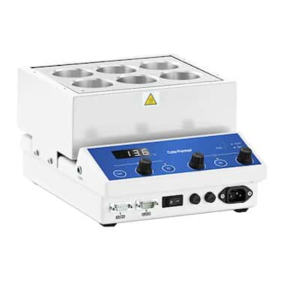
EQUIPMENT OPERATION 7. PRODUCT OPERATION. 7.1. The illustrations below show detailed layouts of the RS-250D-250. 7.1. The illustrations below show detailed layouts of the RS-250D-250. LED Temperature Display Stir On / Off selection button Stir speed control knob Mains power present LED Stir function On indication LED Function Set LED Stir speed Ramp rate setting. - Page 13 7.2. Plug the mains cord with the moulded IEC plug into the IEC socket of the RS-250D-250. Connect the mains plug to the correct voltage mains supply. Check data plate for correct voltage input. 7.3. Turn on the mains electricity and turn on the RS-250D-250 by the On / Off power switch. 7.4.
- Page 14 required temperature figure is displayed. (The display will scroll through from 0 to 9 inclusive). 7.6. Temperature Probe facility (Optional). required temperature figure is displayed. (The display will scroll through from 0 to 9 inclusive). The RS600 has a jack plug socket for the connecting an external probe. (Optional 7.6.
-
Page 15: Technical Specifications
TECHNICAL SPECIFICATIONS 8. TECHNICAL SPECIFICATIONS. 8.1 Specification 8.1. Specification. Mains Supply Power. 230V-AC or 115/100V-AC @ 50/60Hz Mains Supply Power. 230V-AC or 115/100V-AC @ 50/60Hz HH179(S) Mains cord and moulded IEC plug and lead Mains Power Lead set (UK) 13A 3 core earthed / ground. -
Page 16: Maintenance
9. MAINTENANCE 9. MAINTENANCE 9.1. General Information. MAINTENANCE 9. MAINTENANCE. 9.1. General Information. 9.1. General Information. 9.1. General Information. Unplug the unit from the mains voltage supply before undertaking any Unplug the unit from the mains voltage supply before undertaking any maintenance tasks. - Page 17 measurement. SAD allows a calibration of the top part of the measurement scale with a proportional correction between the calibration point and 0 • Press o display the value and then use 9.3. Spillage and Decontamination. to make the read value coincide with the value measured by the reference instrument.
-
Page 18: Spares And Accessories
SPARES AND ACCESSORIES Order Number Description HH179(S) Mains cord and moulded IEC plug and lead set cable (UK) 10A BS1362 HH180(S) Mains cord and moulded IEC plug and lead set cable (Europe) CRM6288 Mains cord and moulded IEC plug and lead set cable (USA) AZS6107 Stir bar, Pack 6. - Page 19 This product meets the applicable CE Directives that interference will not occur in practise. Where and UKCA Legislation for radio frequency there is a possibility that injury, damage or loss might interference and may be expected not to occur if equipment malfunctions due to radio interfere with, or be affected by, other equipment with similar frequency interference, or for general advise before qualifications.
-
Page 20: Declaration Of Conformity
Ordering Information Order No. Series Model Legacy SKU 36630-13 RS-250 RS-250D-250 PS80034 81225-00 RS-250 RS-250D-250-115 PS80043 India Warranty Registration T: +44 (0) 1480 272279 T: +9122 61394444 E: uk.sales@antylia.com E: info@coleparmer.in W: coleparmer.co.uk W: coleparmer.in Germany China T: +49 (0) 9377 92030 T: +1 847 549 7600 E: de.sales@antylia.com E: sales@antylia.com...
Need help?
Do you have a question about the RS-250 Series and is the answer not in the manual?
Questions and answers