
Related Manuals for Cole Parmer POLYSTAT


Summary of Contents for Cole Parmer POLYSTAT
- Page 1 Immersion Circulators Manual P/N U01081 Rev. 01/28/11 Installation Operation...
-
Page 3: Table Of Contents
Table of Contents Preface ........................i Compliance ......................i Warranty ........................i Unpacking ........................i ..................1-1 Section 1 Safety Safety Warnings ....................1-1 ..............2-1 Section 2 General Information Description ......................2-1 Specifications ......................2-1 Wetted Parts ......................2-4 ................3-1 Section 3 Installation Ambient Conditions ..................3-1 Ventilation ......................3-1 Electrical Requirements ..................3-2 Remote Temperature Sensor ................3-3 External Circulation ..................3-4... - Page 4 Contents ............5-1 Section 5 Preventive Maintenance Cleaning ......................5-1 Condenser Fins ....................5-1 Testing the Safety Features ................5-2 Section 6 Troubleshooting ....................6-1 Error Displays ....................6-1 Check List ......................6-3 Appendix Serial Communications ..................1 Cole Palmer...
-
Page 5: Preface
Cole-Parmer will repair or replace the product or provide credit, as its sole option, upon prompt notification and compliance with its instructions. The Distributor warrants to Customer that upon prompt notification and... - Page 6 Preface Cole Palmer...
-
Page 7: Safety
Safety Section 1 Make sure you read and understand all instructions and safety precautions Safety Warnings listed in this manual before installing or operating your unit. If you have any questions concerning the operation of your unit or the information in this manual, please contact us. - Page 8 Section 1 Safety Do not mount the immersion circulator backwards on the bath; the line cord could contact the reservoir fluid. Ensure the electrical cords do not come in contact with any of the plumbing connections or tubing. Operate the unit using only the supplied line cord. If the unit's power cord is used as the disconnecting device, it must be easily accessible at all times.
-
Page 9: General Information
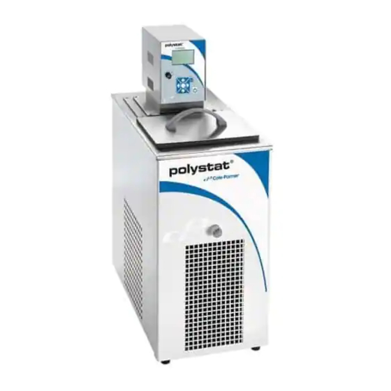
General Information Section 2 Description The Cole Palmer Polystat Immersion Circulators are used with refrigerated ® and heated baths. All circulators can pump to an external system. All have a digital display and easy-to-use touch pad, five programmable setpoint temperatures, acoustic and optical alarms, and offer adjustable high temperature protection. - Page 10 Section 2 General Information Refrigerated Bath/Circulator Specifications Stainless Steel Refrigerated Baths/Circulators with Controller 1 C15++ Temperature Range -20 to 100°C -20 to 100°C -28 to 100°C -35 to 100°C -4 to 212°F -4 to 212°F -18 to 212°F -31 to 212°F Bath Volume liters 3 - 6 3 - 6...
- Page 11 Section 2 General Information Heated Bath/Circulator Specifications Stainless Steel Baths/Circulators with Controller 1 Temperature Range* Ambient +10 to 100°C Ambient +10 to 100°C Ambient +10 to 100°C Ambient +50 to 212°F Ambient +50 to 212°F Ambient +50 to 212°F Bath Volume liters 4 - 7 7 - 11 14 - 24...
- Page 12 Section 2 General Information Polyphenylene oxide (PPO) Baths/Circulators with Controller 1 W14P W21P Temperature Range* Ambient +10 to 100°C Ambient +10 to 100°C Ambient +10 to 100°C Ambient +50 to 212°F Ambient +50 to 212°F Ambient +50 to 212°F Bath Volume liters 3 - 5 8 - 14 13 - 21...
-
Page 13: Installation
Installation Section 3 Ambient Ambient Temperature Range 10°C to 40°C (50°F to 104°F) Conditions Maximum Relative Humidity 80% at 31°C (88°F) Operating Altitude Sea Level to 2000 meters (6560 feet) Overvoltage Category Pollution Degree Degree of Protection IP 20 The unit is designed for continuous operation and for indoor use. Never place the unit in a location where excessive heat, moisture, CAUTION inadequate ventilation, or corrosive materials are present. -
Page 14: Electrical Requirements
Section 3 Installation Electrical The unit construction provides protection against the risk of electrical Requirements shock by grounding appropriate metal parts. The protection will not function unless the power cord is connected to a properly grounded DANGER outlet. It is the user's responsibility to assure a proper ground connection is provided. -
Page 15: Remote Temperature Sensor
Section 3 Installation Ensure all communication and electrical connections are made CAUTION prior to starting the unit. • Ensure the line cord from the bath is securely connected to the rear of the controller. • Ensure the communications cable from the bath is connected to the RJ45 connectors (similar to Ethernet) on the rear of the controller. -
Page 16: External Circulation
Section 3 Installation External The plumbing connections for external circulation are located on the rear of the thermostat. is the return flow from the external application. Circulation the outlet flow to the external application (supply side). The connections are 16 mm O.D. Remove the union nuts and plates to install the 8 mm or 12 mm hose barbs and clamps supplied with the unit. - Page 17 Section 3 Installation 5°C to 95°C — Distilled Water or Deionized Water (up to 3 MΩ-cm) Normal tap water leads to calcareous deposits necessitating frequent unit decalcification, see table on next page. Calcium tends to deposit itself on the heating element. The heating capacity is reduced and service life shortened.
- Page 18 Section 3 Installation Water Quality and Standards Process Fluid Permissible (PPM) Desirable (PPM) Microbiologicals (algae, bacteria, fungi) Inorganic Chemicals Calcium <25 <0.6 Chloride <25 <10 Copper <1.3 <1.0 0.020 ppm if fluid in contact with aluminum Iron <0.3 <0.1 Lead <0.015 Magnesium <12...
-
Page 19: Additional Fluid Precautions
Section 3 Installation Additional Fluid When working with fluids other than water: • Do not use any fluid until you have read and understood the label and Precautions the Material Safety Data Sheet (MSDS). • Do not blend any fluids. •... - Page 20 Section 3 Installation Cole Palmer...
-
Page 21: Operation
Operation Section 4 Controller The Cole Palmer Immersion Circulators have a digital display and easy-to-use touch pad, five programmable setpoint temperatures, acoustic and optical alarms and adjustable high temperature protection. Use this button to place the unit in and out of standby. Use these navigation arrows to move through the controller displays and to adjust values. -
Page 22: Setup
Section 4 Operation Setup Refrigerated units should be left in an upright position at room CAUTION temperature (~25°C) for 24 hours before starting. This will en- sure the lubrication oil has drained back into the compressor. CAUTION Before starting the unit, double check all USB (optional), elec- trical and plumbing connections. -
Page 23: Status Display
Section 4 Operation Status Display If desired, press to toggle between the Start/Status Displays. Refrigeration Running Selected Reservoir Fluid Symbol Pump Running Symbol Water Heater Running Symbol 2 4 . 2 C Reservoir Fluid Temperature Status Display Stand By Mode Press , the display will go blank and the unit will be in the stand by mode. -
Page 24: Changing The Setpoint
Section 4 Operation Changing the NOTE You cannot adjust the setpoint closer than 0.1°C to either of the fluid's system limits, see Fluids Type in this Section, or beyond the Setpoint unit's temperature range. NOTE The setpoint can be changed with the unit running or not. ... -
Page 25: Menu Displays
Section 4 Operation Menu Displays The controller uses menus to view/change the unit's settings. NOTE The unit does not need to be running to view/change these settings. For all Menu displays, once is pressed to change a display, you can press to return to the previous screen. - Page 26 Section 4 Operation Cole Palmer...
- Page 27 Section 4 Operation Settings - Application Settings is used to view/adjust the controller's five Setpoints and Real Temperature Adjustments (RTA) enable/disable the alarms, change the fluid type, set the pump speed, configure the interfaces (optional), set the clock, turn the timer on or off, and turn auto restart and en- ergy savings on or off.
- Page 28 Section 4 Operation Alarms is used to view/adjust the high and low temperature alarm limits, to enable/disable the audible alarms and to configure the optional low level warning reaction. Alarms 1. With highlighted, press Temperature Alarms 2. With highlighted, display: press to display: High Fault 83.0°C...
- Page 29 Section 4 Operation Fluids Type is used to identify the type of fluid used. The controller uses the fluid type to automati- cally set certain operating parameters. Fluid system limits High °C Low °C Fluid Type 1. With highlighted, press display the list of acceptable fluids. All units: Highlight the desired fluid and press Water...
- Page 30 Section 4 Operation On/Off Timer Set Clock is used to enable and set the is used to set the controller's time controller's timer. (hr : min : sec) and date (year - month - day). On/Off Timer 1. With highlighted, press XX : XX : XX to display the on ( ) and off ( ) time as well as...
- Page 31 Section 4 Operation Settings - Display Options is used to view/adjust the controller's Temperature Units, the Temperature Resolution, the displayed Language, and the Display Contrast and Display Delay. Temp. Unit Temp. Resolution 1. With highlighted press 2. With highlighted Use the up/down arrows to highlight the desired press temperature scale.
- Page 32 Section 4 Operation System Messages is used to view any Warning or Fault messages. Messages 1. With highlighted, press display the options. Warnings Faults Menu System Run Time is used to view the unit and pump operating hours. Run Time 1.
- Page 33 Section 4 Operation System - Password/Reset is used only by a qualified technician. Changing the password enables controller reset options, the temperature sensor calibration procedure and displays PID values. 2. Press and change the number to Password/Reset 1. With highlighted, press to display: Level User Level User Password 1...
- Page 34 Section 4 Operation 1. To calibrate the temperature sensor highlight 2. With the desired sensor highlighted, press Calibration to display: and press to display: NOTE Ensure the RTA is set to 0 before doing a calibration. Internal RTD Calibrate External RTD Restore User Cal Save User Cal...
- Page 35 Section 4 Operation 2. Highlight the desired PID and press PID Tuning 1. With highlighted, press display: display: Cool PID xx.x Heat PID x.xx x.xx Menu Menu 3 . If required, press to change the value. xx.x x.xx x.xx Menu Factory values are: P = 05.0 I = 0.10...
-
Page 36: Stopping The Unit
Section 4 Operation Stopping Ensure the stop symbol is highlighted, if not use the arrow keys to navi- gate to the symbol. the Unit Press . The unit will stop and the stop symbol will turn into a start symbol ( Menu 20.0°C Stop Symbol... -
Page 37: Preventive Maintenance
Preventive Maintenance Section 5 Disconnect the power cord prior to performing any maintenance. CAUTION Handle the unit with care. Sudden jolts or drops can damage the unit's components. After time, the unit's stainless steel surfaces may show spots and become Cleaning tarnished. -
Page 38: Testing The Safety Features
Section 5 Preventive Maintenance Testing the Safety The safety features for high temperature protection and low liquid level protection must be checked at regular intervals. The frequency depends on Features the unit’s designated application and the heat transfer fluid used. High temperature protection Set a cut-off temperature that is lower than the desired setpoint temperature. -
Page 39: Troubleshooting
Troubleshooting Section 6 Error Displays Error messages are cleared by pressing the enter key. Once the cause of the error message is identified and corrected, to restart the unit press the enter key again. If the message does not clear contact us. FAULT: HIGH TEMP. - Page 40 Section 6 Troubleshooting • adjustable high temperature protection limit Low Temperature exceeded • check limit setting • check fluid selection • it can take over 10 minutes for the motor Motor Fault temperature to get low enough before the unit can be restarted •...
-
Page 41: Checklist
Section 6 Troubleshooting Checklist Unit will not start Check the controller for error codes, see Error Codes in this section. Ensure the circuit protector is in the on ( I ) position. Make sure supply voltage is connected and matches the unit's nameplate rating ±10% No display on controller Recycle the circuit protector on the rear of the controller. - Page 42 Section 6 Troubleshooting USB Driver Not Recognized If your operating system does not automatically recognize the optional driver log on to: http://www.ftdichip.com/FTDrivers.htm for instructions. Cole Palmer...
-
Page 43: Appendix Serial Communications
NC Serial Communications Appendix Protocol NOTE This appendix assumes you have a basic understanding of communications protocols. All data is sent and received in binary form, do not use ASCII. In the following pages the binary data is represented in hexadecimal (hex) format. The NC Serial Communications Protocol is based on a master-slave model. - Page 44 Appendix NOTE All byte values are shown in hex, hex represents the binary values that must be sent to the chiller. Do not use ASCII. The framing of the communications packet in both directions is: Checksum region Lead char Addr-MSB Addr-LSB Command n d-bytes d-byte 1 d-byte n Checksum CA or CC...
- Page 45 Appendix The master sets parameters in the chiller by sending one of the Set Functions as shown in Table 1. The master does not send a qualifier byte in the data field. The master should be preprogrammed to send the correct precision and units (it could also read the parameter of interest first to decode the correct precision and units needed).
- Page 46 Appendix Table 1 Commands (continued) (All bytes are in hex) FUNCTION MASTER SENDS UNIT RESPONDS Set Setpoint One* CA 00 01 F0 02(d1)(d2)(cs) CA 00 01 F0 03(qb)(d1)(d2)(cs) Set Low Temp Warning CA 00 01 C0 02(d1)(d2)(cs) CA 00 01 C0 03(qb)(d1)(d2)(cs) CA 00 01 C1 02(d1)(d2)(cs) CA 00 01 C1 03(qb)(d1)(d2)(cs) Set Low Temp Fault...
- Page 47 Appendix Table 3 READ STATUS Low Temp Fault High Temp Fault HTC Fault Low Temp Warning MOL Fault High Temp Warning Pump Speed Fault RTD2 Open/Short High RA Temp RDT1 Open/Short HPC Fault Unit Faulted Low Level Fault/Warning Unit Running High Level Fault/Warning Unit of Measure Index...
- Page 48 Year of inception 2011 We declare that the following products conform to the Directives and Standards listed below. Products: Polystat refrigerated and heated liquid baths, non refrigerated heated liquid baths and immersion liquid circulators. Refrigerated and non refrigerated heated liquid baths: Models: C6, C6F, C15 and C15++, W7, W11, W24, W5P, W14P, W21P, W6A, W12A, W19A,.
- Page 49 W19A, all with control head models 1H or 2H or 3H. Polystat immersion circulator models: 1BR, 2BR, 3BR, 1CL and 2CL. Cole Parmer certifies that the above Polystat models meet the requirements of DIRECTIVE 2002/95/EC, Restriction of Hazardous Substances Directive ( RoHS ).
Need help?
Do you have a question about the POLYSTAT and is the answer not in the manual?
Questions and answers