
Related Manuals for SKF LINCOLN SP/SMB3 Series


Summary of Contents for SKF LINCOLN SP/SMB3 Series
- Page 1 Assembly instructions ATEX flow limiters of series SP/SMB3 and SP/SMB6 Version 01 951-230-018-EN...
-
Page 2: Explosion Protection Marking In Accordance With Directive 2014/34/Eu
Explosion protection marking in accordance with Directive 2014/34/EU The ignition hazard analysis conducted in accordance with EN 80079-36 / -37 found that SKF flow limiters of series SP/ SMB3 and SP/SMB6 without electrical at- tachments do not constitute own potential sources of ignition. -
Page 3: Classification As Simple Electrical Equipment
24-1072-2116 ferred for the system. cally safe electrical circuit with maximum 24-1072-2054 values: SKF affixes this marking via the signal 24-1072-2055 transmitter’s blue connection cable or via a Year of manufacture: See type plate blue screw union. = 30 V... -
Page 4: Masthead
Masthead Manufacturer Training Disclaimer of liability SKF Lubrication Systems Germany GmbH SKF conducts detailed training in order to The manufacturer shall not be held liable for Address of manufacturer plants enable the maximum safety and efficiency. damage resulting from: Headquarters SKF recommends taking advantage of this ○... -
Page 5: Table Of Contents
Table of contents Table of contents Explosion protection marking in accordance with Directive 2014/34/EU ...2 Classification as simple electrical equipment ..........3 1.20 First start-up, daily start-up ...............16 Masthead .....................4 1.21 Cleaning ....................17 Explanation of symbols and signs ...............7 1.22 Special safety instructions regarding explosion protection .....17 1.23 Nullification of ATEX approval ..............19 Safety instructions .................9... - Page 6 Table of contents Delivery, returns, storage ............36 Operation ..................55 Delivery ....................36 Temporary shutdown ................55 Return shipment ...................36 Permanent shutdown and disposal ............55 Storage ....................36 Disposing of dismantled parts .............55 Assembly ..................37 Cleaning ..................56 General information ................37 Cleaning agents ..................56 Minimum mounting dimensions ............38 Exterior cleaning ...................56...
-
Page 7: Explanation Of Symbols And Signs
Explanation of symbols, signs, and abbreviations Explanation of symbols and signs General warning Risk of electrical shock Risk of slipping Hot surfaces Being drawn into machinery Crushing hazard Pressure injection Suspended load Electrostatic sensitive Potentially explosive components atmosphere Wear personal protective gear Wear personal protective gear (face Wear personal protective Wear personal protective... - Page 8 Explanation of symbols, signs, and abbreviations Abbreviations and conversion factors regarding °C degrees Celsius °F degrees Fahrenheit approx. approximately Kelvin ounce i.e. that is Newton fl. oz. Fluid ounce etc. et cetera hour inch poss. possibly second pound per square inch if necessary if necessary sq.in.
-
Page 9: Safety Instructions
1. Safety instructions 1. Safety instructions 1.1 General safety instructions 1.2 General behavior when handling the ○ The operator must ensure that the in- ○ Responsibilities for different activities product structions are read by all persons tasked must be clearly defined and observed. ○... -
Page 10: Intended Use
0.5 bar at their maximum are used to monitor the volumetric flow perature range permissible operating temperature within an ATEX-compliant SKF flow limiter. ○ Use of non-specified equipment ○ Use in another, more critical explosion The signal transmitters with built-in dry... -
Page 11: Painting Plastic Components
1. Safety instructions 1.5 Painting plastic components 1.6 Modifications to the product 1.8 Inspections prior to delivery The painting of all plastic components and Unauthorized modifications and changes The following tests were performed prior to seals of the products described here is can have an unpredictable effect on safety. -
Page 12: Referenced Documents
Serial No. _____________________________ ○ Instructions from suppliers of purchased parts ○ Instructions for other components for setting up the centralized lubrication SKF Lubrication Systems Germany GmbH system ○ Other relevant documents for integration Düse of the product into the main machine,... -
Page 13: Note On Ce Marking
1. Safety instructions 1.12 Note on CE marking The CE marking is based on the require- Note on Pressure Equipment Directive here with the explosion-proof electrical com- ments of the applied Directives: 2014/68/EU ponents specified in this manual does not create an additional source of ignition. -
Page 14: Qualified Mechanic
1. Safety instructions 1.13.2 Qualified mechanic 1.16 Provision of personal protective gear A person with appropriate technical train- to rectify these by taking suitable actions. The operator must provide personal protec- ing, knowledge, and experience who can The specialist has knowledge of the various tive gear appropriate for the location and recognize and avoid the hazards that may types of protection, installation procedures,... -
Page 15: Emergency Shutdown
1. Safety instructions 1.18 Emergency shutdown 1.19 Transport, assembly, maintenance, malfunction, repair, shutdown, disposal Shut down the product in an emergency by: during the work and that no limbs can be ○ Prior to the start of this work, all relevant pinched by unintended movements. -
Page 16: First Start-Up, Daily Start-Up
1. Safety instructions 1.20 First start-up, daily start-up ○ Establish the electrical connection only in - The lubricant to be delivered accordance with the valid circuit diagram - The required ATEX zone Ensure that: and in observance of the relevant regula- - The operating and ambient conditions ○... -
Page 17: Cleaning
1. Safety instructions 1.21 Cleaning 1.22 Special safety instructions regarding explosion protection ○ There is a fire hazard from the use of ○ Always behave so as to avoid explosion ○ The introduction of ignition sources such flammable cleaning agents. Use only hazards. - Page 18 1. Safety instructions ○ The minimum ignition temperature and ○ Repairs or modifications to explosion- ○ The product may be cleaned only if there the glow temperature and the surround- proof machinery may be performed only is no potentially explosive atmosphere. ing potentially explosive dusts must be by the manufacturer or a workshop rec- ○...
-
Page 19: Nullification Of Atex Approval
○ Use of non-original SKF spare/replace- ○ At the time of the assembly of the flow ○ All laws and regulations that the operator ment components... -
Page 20: Obligations Of The Operator
1. Safety instructions 1.25 Obligations of the operator 1.25.2 Explosion protection measures ○ Based on a comprehensive assessment ○ Prepares written operating instructions 1.25.1 Identification of hazards of the work area, the operator ensures ○ The operator must identify all hazards ○... -
Page 21: Residual Risks
1. Safety instructions 1.26 Residual risks Possible in Residual risk Avoidance / Remedy lifecycle Personal injury / property damage due Unauthorized persons must be kept away; nobody is allowed to be present below hoisted A, B, C, G, H, K to falling of hoisted parts parts. -
Page 22: Residual Atex Risks
1. Safety instructions 1.27 Residual ATEX risks Residual risk Remedy Operating in a potentially explosive atmosphere Use in a potentially explosive atmosphere ○ Check the equipotential bonding for continuity before first start-up, after every repair, and addition- without checking equipotential bonding for ally at regular intervals defined by the operator electrical continuity ○... - Page 23 1. Safety instructions Residual risk Remedy Operating in a potentially explosive atmosphere Generation of electrostatic charges, sparks by ○ Secure parts against falling; if necessary, cover parts to avoid sparking. dropping of parts Introduction of catalytic, unstable, or pyro- ○ Ensure that none of these substances enter the potentially explosive atmosphere; have all substanc- phoric substances into the potentially explo- es approved by the operator in advance sive atmosphere...
-
Page 24: Lubricants
2. Lubricants 2.1 General information 2.2 Selection of lubricants Lubricants are used specially for specific SKF Lubrication Systems considers lubri- IMPORTANT NOTE applications. To fulfill the task, lubricants cants to be an element of system design. must meet various requirements to varying... -
Page 25: Material Compatibility
"bleeding"). The lubricants must generally be compatible with the following materials: Please contact SKF if you have further ques- tions regarding lubricants. ○ Steel, gray cast iron, brass, copper, aluminum An overview of the lubricants we have tested is available on request. -
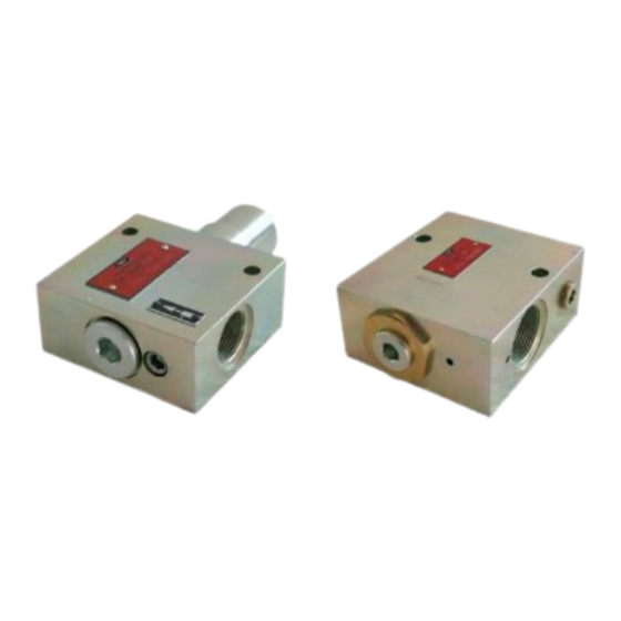
Page 26: Overview, Functional Description
3. Overview, functional description 3. Overview, functional description 3.1 ATEX Flow limiter SP/SMB3 Legend to Figure 1 Overview ATEX flow limiter SP/SMB3, Fig. 1 1 ATEX flow limiter SP/SMB3 1 SP/SMB3 basic design 1.1 Housing Equipotential bonding connection Ø4,3mm 1.3 Lubricant inlet 1.4 Lubricant outlet 1.5 Assembly holes 2 Signal transmitter... -
Page 27: Type Designation
3. Overview, functional description 3.1.1 Type designation SP/SMB 3 A 2E5 / 500 ATEX Example: Example: SP/SMB3A2E5/500 ATEX Assemblies designation Flow limiter Frame size ○ Flow limiter type SP/SMB, size 3, Volumetric flow from 6 to 38 l/min. Factory-set, interchangeable plug-in nozzle used designed for volumetric flows of for adjusting settings 6 to 38 l/min, depending on the... -
Page 28: Atex Flow Limiter Sp/Smb6
3. Overview, functional description 3.2 ATEX Flow limiter SP/SMB6 Legend to Figure 2 Overview ATEX flow limiter SP/SMB6, Fig. 2 1 ATEX flow limiter SP/SMB6 1.1 Housing Equipotential bonding connection Ø4,3mm 1.3 Lubricant inlet 1.4 Lubricant outlet 1.5 Assembly holes 2 ATEX signal transmitter Order No. -
Page 29: Type Designation
3. Overview, functional description 3.2.1 Type designation SP/SMB 6 / 2 E5 /1080/ATEX Example: SP/SMB6/2E5/1080/ATEX Example: ○ Flow limiter type SP/SMB, size 6, Assemblies designation Flow limiter designed for volumetric flows of 25 to Frame size 132 l/min, depending on the nozzle size Volumetric flow from 25 to 132 l/min. -
Page 30: Functional Description Of A Flow Limiter
3. Overview, functional description 3.3 Functional description of a flow limiter See Figure 3 Flow limiters are used in circulating-oil lu- against the spring force (F) automatically in the indicated viscosity range is almost in- brication systems. The task of a flow limiter changes the flow resistance of restrictor D dependent of temperature and viscosity. -
Page 31: Technical Data
4. Technical data 4. Technical data 4.1 General technical data SP/SMB3 and SP/SMB6 Type 2 directional flow limiting valve Operating pressure (inlet) P -without attachments 5 to 200 bar - with signal transmitter E5 (24-1072-2116) 5 to 85 bar - with signal transmitter 4004 (24-1072-2054) 5 to 85 bar - with signal transmitter 4005 (24-1072-2055) 5 to 85 bar... -
Page 32: Flow Limiter Sp/Smb3
4. Technical data Warning! Connect the grounding cable (provided by customer) to the ground terminal. Follow ATEX guidelines! 4.2 Flow limiter SP/SMB3 Nominal volumetric flow stepwise from 6 to 38 l/min, see Chapter 4.4 Inlet thread/Outlet thread G 3/4 Material gray cast iron neutrally anodized Weight 2.6 kg... -
Page 33: Plug-In Nozzle Table Sp/Smb3
4. Technical data 4.4 Plug-in nozzle table SP/SMB3 Nominal volumetric Nozzle Nozzle-Ø Spare part, complete Nominal volumetric Nozzle Nozzle-Ø Spare part, complete flow index [Ø mm] plug-in nozzle D flow index [Ø mm] plug-in nozzle D [l/min] [l/min] 6.00 24-0455-2370 16.75 24-0455-2389 6.50... -
Page 34: Plug-In Nozzle Table Sp/Smb6
4. Technical data 4.5 Plug-in nozzle table SP/SMB6 Nominal volumetric Nozzle index Nozzle-Ø Spare part, com- Nominal volumetric Nozzle index Nozzle-Ø Spare part, com- flow [Ø mm] plete plug-in nozzle flow [Ø mm] plete plug-in nozzle [l/min] [l/min] 14.4 44-0455-2357 1440 / 440 44-0455-2386 44-0455-2360... -
Page 35: Signal Transmitter
4. Technical data 4.6 Signal transmitter Signal transmitter 24-1072-2116 24-1072-2054 24-1072-2055 only for SP/SMB3 only for SP/SMB3 Switching voltage (U) max. 30 V DC Switched current (I) max. 100 mA Switching capacity (P) Max. 40 W Function NC contact, closed contact in go position NC contact, closed contact in go NC contact, closed contact in go position be- between pin 1 and pin 4... -
Page 36: Delivery, Returns, Storage
5. Delivery, returns, storage 5. Delivery, returns, storage 5.1 Delivery ○ The permissible storage temperature After receipt of the delivery, it must be in- The following must be marked on the pack- spected for any shipping damage and for aging of return shipments: range corresponds to the operating tem- completeness on the basis of the shipping perature range (see "Technical data"). -
Page 37: Assembly
6. Assembly 6. Assembly 6.1 General information ○ No radial or axial active forces may occur ○ Carefully clean screw unions and tubing Only qualified technical personnel may install at the flow limiter. prior to beginning installation. the products specified in the instructions. ○... -
Page 38: Minimum Mounting Dimensions
Only ATEX-compliant screw unions, ing lubricant is hazardous. It cre- which is determined by the maxi- lines, SKF attachments, and SKF ates a risk of slipping and injury. mum permissible pressure of the monitoring equipment may be in- Beware of any lubricant leaking flow limiter design –... -
Page 39: Assembling The Flow Limiters Sp/Smb3 And Sp/Smb6
6. Assembly 6.3 Assembling the flow limiters SP/SMB3 and SP/SMB6 See Figures 4 to 9 SP/SMB6 Use the torque of the fitting manufacturer ○ Hexagon head screws, 2x acc. to DIN EN for inlet and outlet screw unions ISO 4017, M12, strength class 8.8 The mounting surface for the attachment •... -
Page 40: Assembly Drawing Sp/Smb3
6. Assembly 6.3.1 Assembly drawing SP/SMB3 Flow limiter SP/SMB3, Fig. 4 Inlet thread/Outlet thread G3/4 Inlet Ultimate length plug screw Ø8.4 34.5 Ultimate length 64.5 Nozzle holder Minimum mounting dimensions 83.5 T = Width: L = Length: Outlet H = Height: - 40 - 951-230-018-EN Version 01... -
Page 41: Assembly Drawing Sp/Smb3 With Signal Transmitter 24-1072-2116
6. Assembly 6.3.2 Assembly drawing SP/SMB3 with signal transmitter 24-1072-2116 Flow limiter SP/SMB3 with signal transmitter 24-1072-2116, Fig. 5 Signal transmitter Inlet Ultimate length Outlet signal transmitter Minimum mounting dimensions T = Width: L = Length: H = Height: - 41 - 951-230-018-EN Version 01... -
Page 42: Assembly Drawing Sp/Smb3 With Signal Transmitter 24-1072-2054
6. Assembly 6.3.3 Assembly drawing SP/SMB3 with signal transmitter 24-1072-2054 Flow limiter SP/SMB3 with signal transmitter 24-1072-2054, Fig. 6 Signal transmitter Inlet Outlet Minimum mounting dimensions T = Width: L = Length: H = Height: - 42 - 951-230-018-EN Version 01... -
Page 43: Assembly Drawing Sp/Smb3 With Signal Transmitter 24-1072-2055
6. Assembly 6.3.4 Assembly drawing SP/SMB3 with signal transmitter 24-1072-2055 Flow limiter SP/SMB3 with signal transmitter 24-1072-2055, Fig. 7 Signal transmitter Inlet Outlet Minimum mounting dimensions T = Width: L = Length: H = Height: - 43 - 951-230-018-EN Version 01... -
Page 44: Assembly Drawing Sp/Smb6
6. Assembly 6.3.5 Assembly drawing SP/SMB6 Flow limiter SP/SMB6, Fig. 8 Inlet Ultimate length Ø12 Minimum mounting dimensions nozzle holder Ultimate length T = Width: plug screw L = Length: Inlet thread/Outlet thread G1 1/4 Outlet H = Height: - 44 - 951-230-018-EN Version 01... -
Page 45: Assembly Drawing Sp/Smb6 With Signal Transmitter 24-1072-2116
6. Assembly 6.3.6 Assembly drawing SP/SMB6 with signal transmitter 24-1072-2116 Flow limiter SP/SMB6 with signal transmitter 24-1072-2116, Fig. 9 Inlet Ultimate length signal transmitter Outlet Minimum mounting dimensions T = Width: L = Length: H = Height: - 45 - 951-230-018-EN Version 01... -
Page 46: Signal Transmitter Connection
6. Assembly 6.4 Signal transmitter connection 6.4.2 Application 6.4.1 General information Signal transmitters of series The signal transmitter 24-1072-2116 is for 24-1072-2116, 24-1072-2054 and use with ATEX flow limiters SP/SMB3 DANGER 24-1072-2055 may only be installed, con- and SP/SMB6. nected, and commissioned by technical per- The signal transmitters 24-1072-2054 and Excessive switching voltage hazard sonnel. -
Page 47: Designs
6. Assembly 6.4.3 Designs 6.4.4 Signal transmitter 24-1072-2116 see Figs. 10, 11 and 12 See Figure 10 • Loosen the entire cable socket (1) from • Attach and tighten the connection socket The signal transmitters of series 24-1072-2116, 24-1072-2054 and the signal transmitter (2) (3) to the housing (4) 24-1072-2055 have three switch settings. - Page 48 6. Assembly Assembly signal transmitter 24-1072-2116, Fig. 10 (not assigned) Switch position in case of clogged nozzle (not assigned) View A Go position / normal position Switch position when pressure/volume inadequate - 48 - 951-230-018-EN Version 01...
-
Page 49: Signal Transmitter 24-1072-2055
6. Assembly 6.4.5 Signal transmitter 24-1072-2055 See Figure 11 • Attach the cable gland (3) with thrust • Detach the cable socket (1) from the plate (4) and packing ring (5) to the cable signal transmitter (2), unscrew the cable socket (1) and tighten it. - Page 50 6. Assembly Assembly signal transmitter 24-1072-2055, Fig. 11 Switch position in case of: 1- clogged nozzle 2- Go position / normal position 5 / 4 3 3 - pressure/volume inadequate - 50 - 951-230-018-EN Version 01...
-
Page 51: Signal Transmitter 24-1072-2054
6. Assembly 6.4.6 Signal transmitter 24-1072-2054 See Figure 12 • Arrange the ATEX power lead (3) from Assembly signal transmitter 24-1072-2054, Fig. 12 the signal transmitter to the port without Switch position in case of: any kinks. Observe the maximum clamping limit for the terminal clamps ("Technical data"... -
Page 52: Establishing Equipotential Bonding
6. Assembly 6.5 Establishing equipotential bonding See Figure 13 Equipotential bonding, Fig. 13 WARNING • Loosen the clamping screw (2) on the Follow ATEX guidelines when con- ground terminal (1) Equipotential bonding connec- necting the equipotential bonding tion (screw M6) •... -
Page 53: Lubrication Line Connection
6. Assembly 6.6 Lubrication line connection Secure the centralized lubrication CAUTION system against excessive pres- Risk of slipping sure using an appropriate pres- Exercise caution when handling sure regulating valve. lubricants. Immediately bind and remove any leaked lubricants. Observe the following assembly information for safe and trouble-free operation. -
Page 54: First Start-Up
7. First start-up 7. First start-up To ensure safety and functionality, the person specified by the operator is required to perform the following inspections. Any detected de- ficiencies must be remedied prior to initial start-up. The correction of deficiencies must be done exclusively by a specialist competent and authorized to do so. -
Page 55: Operation
8. Operation 8. Operation 8.1 Temporary shutdown 8.3 Disposing of dismantled parts SKF products operate largely automatically. The activities required during normal opera- Temporary shutdown is performed by dis- Dispose of or recycle electrical tion are limited primarily to cleaning of the connecting the hydraulic supply line. -
Page 56: Cleaning
This prevents the formation The flow limiters must be Please contact SKF Customer Service. of alkaline deposits. kept closed without fail during cleaning. - 56 - 951-230-018-EN... -
Page 57: Maintenance
10. Maintenance Maintenance 10.1 Maintenance for flow limiters 10.2 Maintenance schedule Maintenance inter- Careful and regular maintenance is required Maintenance table, Table 1 of 2 Checklist vals [Months] in order to detect and remedy possibly mal- Activity to be performed Inspection Change functions in time. - Page 58 10. Maintenance Maintenance intervals Maintenance table, Table 2 of 2 Checklist [Months] Activity to be performed Inspection Change Check that protective earthing system fully present, properly connected, and electrically continuous No accumulated dust present Annually With varnished surfaces: Varnishing is fully present; no parts of the varnishing are missing 1) The maintenance intervals depend greatly on the degree of cleanliness and contamination of the lubricant used, they are therefore only reference values.
-
Page 59: Replacing A Plug-In Nozzle
10. Maintenance 10.3 Replacing a plug-in nozzle 10.3.1 Changing the plug-in nozzle SP/SMB3 See Figure 14 • Interrupt oil feed to flow limiter (1) F A brass fitting mandrel (ø 10 mm) (never CAUTION use a hard object such as a screwdriver) •... -
Page 60: Changing The Plug-In Nozzle Sp/Smb6
10. Maintenance 10.3.2 Changing the plug-in nozzle SP/SMB6 See Figure 15 • Interrupt oil feed to flow limiter (1) F A brass fitting wedge (never use a hard object such as a screwdriver) should be CAUTION • Remove plug screw (2) with hexagon used to subsequently help press the Burn injury hazard! socket screw key (WAF 10) and pull it out... - Page 61 10. Maintenance Changing the plug-in nozzle SP/SMB3, Changing the plug-in nozzle SP/SMB6, Fig. 14 Fig. 15 Flow limiter housing Flow limiter housing Plug screw Plug screw Nozzle holder Nozzle holder Interchangeable plug-in nozzle Interchangeable plug-in nozzle Packing ring Packing ring Spring Spring Stop screw...
-
Page 62: Malfunctions, Causes, And Remedies
Malfunctions, causes, and remedies The following table provides an overview WARNING WARNING of possible malfunctions and their causes. Contact the SKF Service department if you System pressure Burn injury hazard! cannot remedy the malfunction. The described component is pressur- Escaping oil is possibly hot. -
Page 63: Repairs
12. Repairs Repairs 12.1 Replacement of signal transmitter WARNING DANGER DANGER Risk of injury Hazard from excessive connected Hazard from incorrect tool or At a minimum, the following safety loads (P equipment measures must be taken before any If a signal transmitter is used in a Use only tools and clothing ap- repairs: potentially explosive atmosphere, an... -
Page 64: Replacement Of Signal Transmitter 24-1072-2116
12. Repairs 12.1.1 Replacement of signal transmitter 24-1072-2116 See Figure 16 • Attach the signal transmitter (3) at the Signal transmitter 24-1072-2116, Fig. 16 • Depressurize the signal transmitter (1) flow limiter (1) and screw it in by hand • Tighten the signal transmitter with box At the defective signal transmitter: wrench (WAF 32) •... -
Page 65: Replacement Of Signal Transmitter 24-1072-2054
12. Repairs 12.1.2 Replacement of signal transmitter 24-1072-2054 • At the signal transmitter (2), check the O- See Figure 17 Signal transmitter 24-1072-2054, Fig. ring (4) for correct seating • Depressurize the signal transmitter • At the signal transmitter, insert hexagon At the defective signal transmitter: socket screws (3) (4x), attach the signal transmitter to the flow limiter... -
Page 66: Replacement Of Signal Transmitter 24-1072-2055
12. Repairs 12.1.3 Replacement of signal transmitter 24-1072-2055 See Figure 18 • At the signal transmitter (3), check the O- • Depressurize the signal transmitter (1) Signal transmitter 24-1072-2055, Fig. ring (5) for correct seating • At the signal transmitter(3), insert hexa- At the defective signal transmitter: gon socket screws (4) (4x), attach the •... -
Page 67: Shutdown, Disposal
13. Shutdown, disposal Shutdown, disposal 13.1 Temporary shutdown 13.3 Disposal Dispose of or recycle electrical Temporary shutdown is performed by: Countries within the European Union components in accordance with ○ Switching off the main machine Waste should be avoided or minimized to WEEE Directive 2012/19/EU. -
Page 68: Spare Parts
14. Spare parts Spare parts The spare parts groups are used exclusively as replacement for defective parts identical in construction. Modifications to existing products by the use of spare parts are therefore not permitted. ATEX flow limiter Pcs. Item number SP/SMB3 ATEX flow limiter SP/SMB3 -without nozzle and signal transmitter On request... - Page 70 The Power of Knowledge Engineering Bearings Lubrication Over the course of more than a century, SKF has specialized in five fields of competence and acquired a Seals and Bearing Systems Units wide range of application expertise. We utilize this experience to provide innovative solutions to OEMs and other manufacturers in practically all industrial sectors worldwide.
Need help?
Do you have a question about the LINCOLN SP/SMB3 Series and is the answer not in the manual?
Questions and answers