
Related Manuals for SKF GVP-S-025-4


Summary of Contents for SKF GVP-S-025-4
- Page 1 Installation and operation manual Grease injection lubrication system GVP-S-025-4 Version Date of issue December 2014 Publication number 951-130-453-S025-4 Languages Country/Countries ...
-
Page 3: Table Of Contents
5.3 Storage ............18 Or an SKF Service Center, the addresses of which are given on our website: 6 Commissioning . -
Page 4: Incorporation
Information concerning the EC Declaration of Conformity and the EC Declaration of Incorporation For the product(s) designated below: – When used as intended, the products supplied by SKF do not reach the limit values listed in the Article 3 par. 1, sections 1.1 to Grease injection lubrication system 1.3 and par. -
Page 5: General
General Meaning of symbols and corresponding information In this manual, the symbols and safety wordings shown on this page are intended to communicate a particular risk to persons, material assets, or the environment. All safety instructions must be respected by person exposed to these risks. -
Page 6: Safety Instructions
1 Safety instructions Unless otherwise noted, products of SKF must not be used in con- junction with explosive atmospheres according to the ATEX-Directive 2014/34/EU. 1.2 Authorized personnel These instructions must be read and understood by all The products described in the installation instructions may only be persons who are involved with the installation, operation, installed, operated, maintained, and repaired by qualified experts. -
Page 7: Warranty
CLP regulation (EC 1272/2008), and identified with hazard picto- nally select the appropriate lubricant, with the help of the lubricant grams GHS01-GHS06 and GHS08, can only be used to feed the SKF supplier. When selecting a lubricant, the type of bearing/wear point,... -
Page 8: Lubricants And The Environment
D A N G E R ! D A N G E R ! Only lubricants that have been approved by SKF for use Centralized lubrication systems must be absolutely leak- with the product may be used. Unsuitable lubricants can cause free. -
Page 9: Construction And Operation
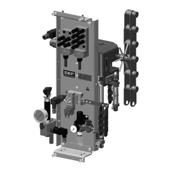
The main functions are the same. They might be also some slight dimension differences. For further information, please refer to the technical documentation delivered with the GVP system or contact the SKF Service Center. Legend fig. 1 1 Injector cylinder 2 Injector carriage... - Page 10 Fig. 2 GVP-S-025-4G dimensions ±5 ±5 (655) ~288 ±5 ~245...
-
Page 11: Function
3.2 Function 3.2.1 Lubrication unit A chain lubrication system comprises the different pneumatic, hy- draulic, mechanical and electronic components necessary to an opti- mal lubrication. The figure beneath shows an example of a lubrica- tion installation. It comprises the following main elements: •... - Page 12 3.2.2 GVP system The function principle of the grease injection system for the lubrica- tion of conveyor chains is more or less the same for all systems. However some models differ from others by the type of lubrication points, the number of injection heads, etc. In the following description of the GVP system function the chain runs upwards.
- Page 13 Injection phase • The capstan is blocked by the stop • The chain moves the carriage with the injector • When the carriage starts, the injector cyl- inder is actuated • The injector comes in contact with the roller greaser Lubricant injection •...
-
Page 14: Installation Instructions
Country-specific accident prevention regulations and the operat- brication system. If you do not have this drawing, please contact ing and maintenance instructions for the operator must be observed the SKF Service Centre to get it. when carrying out all installation work on machines. Moving direction You have to take in account the moving direction of the chain when installing the lubrication system. -
Page 15: Mechanical Adjustments
4.2 Mechanical adjustments D A N G E R ! Adjustments to the pick-up system must only be made when the pneumatic feed is shut off and the chain stopped. The position of the lubrication system must be mechanically adjust to optimize the lubrication process. - Page 16 4.2.1.3 C axis Fig. 7 It is possible to adjust a little the position of the injector with regard to the C axis. Therefore screw on or unscrew the stop head († pos. 1 fig. 6) to slightly modify the axis of the capstan finger. Fig.
-
Page 17: Pneumatic Connection
4.2 Pneumatic connection 4.3.1 Supply pump The lubrication system must be connected to the client's compressed The lubricant supply pump must be located as close as possible to air network. the GVP system. The compressed air quality must comply with purity class 5 de- In the case the pump supplies simultaneously several GVP sys- fined by DIN ISO 8573-1: tems, it must be located in the middle of the system to get an equal... -
Page 18: Electric Connection
It might be necessary to adjust the position of the proximity switch according to the chain speed and the system response time. This manual adjustment is done empirically. Therefore SKF recommends to use a switch support with an ob- long hole parallel to the chain to make the adjustment easier. - Page 19 Fig. 12 It is important to correctly position the proximity switches in relation with the lubrication point to guarantee an optimal function. The proximity switches must be perfectly positioned in the axis of the point to be detected († fig. 12). Sa : 0 <...
-
Page 20: Transport, Delivery And Storage
5 Transport, delivery and storage 5.1 Transport SKF products are packaged in accordance with the regulations of the recipient country and in accordance with DIN ISO 9001. Our prod- ucts must be transported with care. Products must be protected against mechanical influences such as impacts. Transport packaging must be labeled with the information 'Do not drop!'. -
Page 21: Commissioning
6 Commissioning • Switch on the AEP3 control unit. • Pass a metallic object in front of the optional DOC origin sensor (option): the LED should light up 6.1 General • Check that the following LEDs light up: Before starting the lubrication unit, check that all outer connec- –... -
Page 22: Modification Of The Injector Metered Volume
6.3 Modification of the injector metered Fig. 15 volume 0,5 cm 1 cm The GVP lubrication system is delivered with a fixed metered volume. It is possible to modify later this metered volume. Four different me- tered volumes are available: 0,33 ; 0,5 ; 0,75 or 1 cm /stroke. - Page 23 Fig. 18 The lubrication system GVP must be disconnected from the power supply and not under pressure when modifying the metered volume. Therefore turn off the power supply and depressurize the system. • Check the GVP unit is off and the air supply closed. •...
-
Page 24: Lubrication System Bleeding
6.4.2 Lubrication system bleeding Fig. 22 The supply system shown here to describe how to bleed the lubrication system is given as example. This is a pneu- matic drum pump controlled by an pneumatic control unit. Ac- cording to the application, the supply system may be different. For further information, please refer to the technical documenta- tion delivered with the lubricant supply system. -
Page 25: Shutdown
Lubricants can contaminate the ground and watercourses. Lubricants must be used and disposed of in compliance with the rules. Instructions and local regulations must be observed when handling lubricants. The system can also be taken back by SKF for disposal if the costs are covered. -
Page 26: Maintenance
SKF products are low-maintenance. However, to ensure that they function properly and to avoid risks right from the startup, all joints and connections should be checked to make sure that they are prop- erly fitted. -
Page 27: Failures
Doing so invalidates all Table 2 gives an overview of possible malfunctions and their causes. warranty claims. If you are unable to rectify the malfunction, please contact SKF Ser- All other work relating to installation, maintenance, and repair vice Center. -
Page 28: Spare Parts
10 Spare parts Only original SKF spare parts may be used. It is prohibited for the operator to make alterations to the product or to use non original spare parts and resources. Table 5 († fig. 25) Spare part list GVP-S-025-4 Pos. - Page 29 B-B ( 1 : 1 ) A ( 1 : 4 ) ( 1 : 2 )
-
Page 30: Technical Data
11 Technical data Table 6 Technical data GVP-S-025-4 system Air feed pressure 5 to 7 bar Injection volume 0,33 to 1 cm (factory setting 1 cm Operating temperature 5 to 45 °C Lubricant grease NLGI grade 2 Chain max. speed 15 m/min max. - Page 32 The contents of this publication are subject to the publisher's copyright and their reproduction, even partial, is prohibited without prior writ- ten permission. The greatest care has been taken to ensure accuracy of the information contained in this publication, however, SKF declines any responsibility for any losses or damages, direct or indirect, arising from the use of the information contained herein.
Need help?
Do you have a question about the GVP-S-025-4 and is the answer not in the manual?
Questions and answers