Table of Contents
Advertisement
Quick Links
Advertisement
Table of Contents

Related Manuals for SKF PSG Series


Summary of Contents for SKF PSG Series
- Page 1 Component Lifecycle Manual (CLM) Operating instructions acc. to EC Dir. 94/9/EC (ATEX) Modular Feeders of Product Series PSG for oil, grease, and fluid grease, for use in SKF ProFlex, MultiFlex, and circulating oil centralized lubrication systems Version 01...
- Page 3 The instructions do not contain any infor- contact: and must be kept for future use. mation on the warranty. This can be found in the General Conditions of Sales, which SKF Lubrication Systems Germany GmbH are available at: Berlin Plant www.skf.com/lubrication. Motzener Strasse 35/37 12277 Berlin Copyright / Integration of instructions ©...
- Page 4 Table of contents Table of contents Modular Feeders of Product Series PSG Explanation of symbols and signs 1. Safety instructions 2. Lubricants 5. Delivery, returns, and storage General safety instructions General information Checking the delivery General behavior when handling Selection of lubricants Returns the product Approved lubricants...
-
Page 5: Table Of Contents
Table of contents 6.4.10 PSG2 with 2/2 directional solenoid 6.6.8 PSG3 with flow controller for oil PSG1 ATEX feeder series applications valve for oil applications PSG1 feeders for ATEX-compliant applications 6.6.9 PSG3 with 4/2 directional PSG2 ATEX feeder series solenoid valve for oil applications 6.3.1 Information on PSG1 ATEX feeders PSG2 feeders for ATEX-compliant applications... - Page 6 Table of contents 6.15 Note on the rating plate 11. Spare parts 7. Commissioning 12. Accessories General information Commissioning 7.2.1 Venting a grease progressive system 93 7.2.2 Venting an oil progressive system 8. Operation/decommissioning and disposal 96 Temporary shutdown Recommissioning Decommissioning and disposal 9.
- Page 7 Explanation of symbols and signs Explanation of symbols and signs You will find these symbols, which warn of Read the instructions completely and follow Possible symbols specific dangers to persons, material assets, all operating instructions and the warning Meaning Symbol or the environment, next to all safety in- and safety instructions.
- Page 8 Explanation of symbols and signs Instructions placed directly on the product, Abbreviations and conversion factors such as: Abbreviations o Arrow indicators °C degrees Celsius sq.in. square inch seconds kilopond o Fluid connection labels dB (A) sound pressure level cu.in. cubic inch o Warnings i.e.
- Page 9 1. Safety instructions 1. Safety instructions 1.1 General safety instructions 1.2 General behavior when handling the product The operator must ensure that the instruc- o Personnel must familiarize themselves o Protective and safety mechanisms can- tions are read and fully understood by all with the functions and operation of the not be removed, modified, nor disabled persons tasked with working on the product...
- Page 10 1.5 System pressure or hydraulic pressure hazard Only qualified technical personnel may install, Product training can also be performed by operate, maintain, and repair the products SKF in exchange for costs incurred. WARNING described here. Such persons are familiar with the relevant System pressure...
- Page 11 1. Safety instructions 1.6 Operation 1.7 Assembly / maintenance / malfunction / decommissioning / disposal The following must be observed while working All relevant persons (e.g., operating personnel, o Ensure proper grounding of the product. on the product. supervisors) must be informed of the activ- o Drill holes required for assembly only on o All information within this manual and ity prior to beginning work.
- Page 12 1. Safety instructions 1.8 Intended use 1.9 Foreseeable misuse Modular feeders (progressive feeders) of the Modular feeders of the series PSG are Any usage of the product differing from series PSG are designed for positively driven classified as components according to the aforementioned conditions and stated distribution of lubricants (oils/greases) in the VDMA Position Paper "Umsetzung...
- Page 13 Only the feeder types tested and approved o The electrical circuit of the piston detector for damage resulting from: by SKF in accordance with ATEX Directive or proximity switch must be established by 2014/34/EU are permitted to be used in an intrinsically safe circuit, e.g., through...
- Page 14 Directive country of use. The documentation must be 67/548/EEC included if the product is transferred to a o Non-compliant usage new operator. o Installation of non-original SKF components o Failure to comply with this manual and referenced manuals.
- Page 15 1. Safety instructions 1.13 Residual risks Residual risk Remedy Life cycle: Assembly People slipping due to contamination of • Exercise caution when connecting the product’s hydraulic connections floor with spilled/leaked lubricant • Promptly apply suitable binding agents and remove the leaked/spilled lubricant. •...
- Page 16 EC Directive 67/548/EEC, Article 2, Para. of the lubricants are critically important in When selecting a lubricant, the type of 2, may only be filled into SKF centralized making these selections. bearings/friction points, their expected load lubrication systems and components and...
- Page 17 The product described here can be operated NOTE NOTE using lubricants that meet the specifica- If necessary, SKF Lubrication Systems can Only lubricants approved for the product tions in the technical data. Depending on the help customers to select suitable compo- may be used.
- Page 18 2. Lubricants 2.4 Lubricants and the environment 2.5 Lubricant hazards NOTE WARNING NOTE Lubricants can contaminate soil and wa- Lubricants Follow the safety instructions on the terways. Lubricants must be properly used Pumps must always be free of lubricant's safety data sheet. and disposed of.
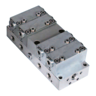
- Page 19 3. Overview/functional description 3. Overview / functional description 3.1 Overview of progressive feeders General Types and frame sizes, Fig. 1 Modular feeders (progressive feeders) of the series PSG are designed for positively driven distribution of lubricants (oils/greases) in 6 000 6 000 PSG3 centralized lubrication systems.
- Page 20 3. Overview/functional description 3.2 Information on volume data In centralized lubrication systems, the nom- feeder and the control edges on the metering Maximum stroke and compulsory stroke, inal volume is indicated per stroke. This is piston. If only the compulsory stroke is per- Fig.
- Page 21 3. Overview/functional description 3.3 Overview of a general progressive system Example of progressive system with pump unit, Fig. 3 Legend to Fig. 3 Progressive system with function monitoring Pump unit with: Pressure regulating valve - Control unit - Fill level control Main lubricant line Master feeder (VP) Function monitoring...
- Page 22 3. Overview/functional description 3.3.1 Functional description of a general progressive system A general progressive feeder system consists lubricant to the secondary feeders according o pushbutton to trigger an interim of the following components: to their individual volume requirements. lubrication o Pump unit with pump element and pres- From there, the lubricant flows to the lubri- o Internal fill level monitoring;...
- Page 23 3. Overview/functional description 3.4 Functioning of a PSG progressive feeder See Figure 4 duct to outlet 3. This movement of piston Sectional view of PSG, Fig. 4 Observation of the movements beginning C opens, among others, the reversing duct with the moment that all three pistons (A, that reconnects the through-duct with pis- B, C) on the left end stop shows that the ton A-right.
- Page 24 3. Overview/functional description 3.5 Information on the design of a PSG progressive feeder The general criteria for the design of pro- baseplate that is no longer needed is to be for this purpose are to be used. The smallest gressive feeders also apply without restric- closed using a washer and a screw plug;...
- Page 25 4. Technical data 4. Technical data 4.1 PSG1 technical data PSG1, Technical data (Table 1 of 2) General Design Hydraulically controlled Mounting position Ambient temperature range -15°C to + 110°C with piston detector -15°C to + 80°C with cycle indicator -15°C to + 75°C with proximity switch...
- Page 26 4. Technical data PSG1, Technical data (Table 2 of 2) Lubricant Mineral oils, greases based on mineral oil, environmentally friendly and synthetic oils and greases Operating viscosity > 12 mm Worked penetration ≥ 265 x 0.1 mm (up to NLGI Grade 2) Weight Piston detector 0.12 kg...
- Page 27 4. Technical data PSG1, Technical data, Pressure loss chart, Fig. Measurement prerequisites Measurement prerequisites Oil viscosity: 150 cSt Oil viscosity: 357 cSt Test medium: ISO VG 150 Test medium: ISO VG 150 (viscosity index 92) (viscosity index 92) Oil temperature: + 40°C Oil temperature: + 26°C Measurement was performed on a Measurement was performed on a...
- Page 28 4. Technical data 4.2 PSG2 technical data PSG2, Technical data, (Table 1 of 4) PSG2, Technical data, (Table 2 of 4) General Inlet volumetric flow Up to 2.5 l/min Design Hydraulically controlled with flow limiter 0.08 to 2.5 l/min Mounting position 60, 120, 240, 360, 480, 600, 720, 840 mm Volume per cycle and outlet Ambient temperature range...
- Page 29 4. Technical data PSG2, Technical data, (Table 3 of 4) PSG2, Technical data, (Table 4 of 4) Weight Gear-type flow indicator Piston detector 0.12 kg Design Hall sensor (PNP technology) Cycle indicator 0.05 kg Rated voltage 24 V DC Residual ripple ≤...
- Page 30 4. Technical data 4.3 PSG3 technical data PSG3, Technical data (Table 1 of 5) PSG3, Technical data (Table 2 of 5) General Inlet volumetric flow Up to 6 l/min Design Hydraulically controlled with flow limiter 0.1 to 6.2 l/min Mounting position 2 l/min to 6 l/min Gear-type flow indicator Ambient temperature range...
- Page 31 4. Technical data PSG3, Technical data (Table 3 of 5) PSG3, Technical data (Table 4 of 5) Filter unit/interchangeable strainer Gear-type Proximity switch flow indicator 0.3 mm Design PNP with LED Flow controller 0.3 mm Rated voltage 10 to 30 V DC Flow limiter 0.3 mm Load current...
- Page 32 4. Technical data PSG3, Technical data (Table 5 of 5) Flow controller Design 2-way flow control valve Settings range 0.1 to 2.5 l/min Filter unit/interchangeable strainer 0.3 mm Scale graduation 1 - 10 Flow limiter Design 2-way flow control valve Filter unit/interchangeable strainer 0.3 mm 4/2 directional solenoid valve Design...
- Page 33 5. Delivery, returns, and storage 5. Delivery, returns, and storage 5.1 Checking the delivery 5.3.2 Electronic and electrical devices o Dry and dust-free surroundings, storage Immediately after receipt, the delivery must in well ventilated dry area WARNING be checked for completeness according o Storage time: Max.
- Page 34 6. Assembly 6. Assembly 6.1 Installation information Modular feeders (progressive feeders) of the o Before installing the feeder, ensure that Such persons are familiar with the relevant series PSG can be used in the context of the all holes, screw unions, and connecting standards, rules, accident prevention regu- technical specifications given in the chapter lines that the feeder contacts are clean...
- Page 35 6. Assembly 6.2 Installing the PSG1 6.2.1 Minimum mounting dimensions/clearance and tightening torques Legend to Fig. 6 Minimum mounting dimensions/clearance for installation, Fig. 6 Number of Dim. A+30 mm Example: Crossporting, 3-bridge, with Maß A + 30 mmm modules [mm] outlet, with check valve Dim.
- Page 36 6. Assembly 6.2.2 PSG1 basic design PSG1 in basic design, Fig. 7 PSG1 in basic design Feeder module Dummy module Note! (26,5) 19.5 The inlet screw union and the outlet screw Baseplate Outlet G1/8 Legend to Fig. 7 unions are not included in the basic design (see Technical data- see Chapter 4.1 Ø6.5...
- Page 37 6. Assembly 6.2.3 PSG1 with piston detector (P3) PSG1 with piston detector (P3), Fig. 8 PSG1 with piston detector 38.5 M12x1 Legend to Fig. 8 Öffner Technical data- see Chapter 4.1 Minimum mounting dimensions: Piston detector 177-300-095 Fig. 6, Legend 6 Feeder dimensions: Basic design Fig.
- Page 38 6. Assembly 6.2.4 PSG1 with visual cycle indicator (ZY) PSG1 with visual cycle indicator (ZY), Fig. 9 PSG1 with visual cycle indicator (ZY) Legend to Fig. 9 Technical data- see Chapter 4.1 Note! Minimum mounting dimensions: A visual cycle indicator can only be Fig.
- Page 39 6. Assembly 6.2.5 PSG1 with visual cycle indicator, housing, and proximity switch (ZS) PSG1 with visual cycle indicator, housing, and proximity switch (ZS), Fig. 10 PSG1 with proximity switch Legend to Fig. 10 Schließer Technical data- see Chapter 4.1 38.5 Inlet Minimum mounting dimensions: Fig.
- Page 40 When used in conformity with their intended ATEX Directive. use, the products supplied by SKF Lubrica- tion Systems Germany AG do not reach the limit values listed in Article 3, Para. 1, Claus- es 1.1 to 1.3 and Para.
-
Page 41: Information On Psg1 Atex Feeders
The installation of other ATEX-compliant Excessive switching voltage attachments or monitoring equipment hazard ATEX feeders of the PSG series, without at- requires mandatory consultation with and An isolating amplifier must be in- tachments and monitoring units, differ from approval from SKF Lubrication Systems... - Page 42 6. Assembly See Figure 11 Only technical personnel may mount, con- • Connect the grounding cable (provided by nect, and put into operation the ATEX PSG customer) to the ground terminal (1). feeders described here. The technical per- sonnel must have detailed knowledge of the Tightening torques various types of protection and the rules and Item...
-
Page 43: Psg1 Atex Basic Design
General for cable clamp Design Hydraulically controlled Ø 4.3 mm Mounting position 24-3710-0044-ATEX SKF Lubrication Systems Germany AG Ambient temperature range II 2D c IIIC T135°CDb II 2G c IIC T4Gb XYZ KW/JJ Made in Germany -15°C to +110°C Baseplate with... -
Page 44: Psg1 Atex Feeder With Plunger Rod
NAMUR DIN EN 50227 Ø 4.3 mm Connection To approved switching amplifiers with max. values 24-3710-0044-ATEX SKF Lubrication Systems Germany AG II 2D c IIIC T135°CDb II 2G c IIC T4Gb XYZ KW/JJ U=15 V; I=50 mA; P=120 mW Made in Germany... - Page 45 6. Assembly...
-
Page 46: Installing The Psg2
6. Assembly 6.4 Installing the PSG2 6.4.1 Minimum mounting dimensions/clearance and tightening torques Legend to Fig. 13 Minimum mounting dimensions/clearance for installation, Fig. 13 Number of Dim. A+30 mm Example: Crossporting, 3-bridge, with outlet, modules [mm] with check valve, for G1/4, Maß... -
Page 47: Psg2 Basic Design
6. Assembly 6.4.2 PSG2 basic design PSG2 in basic design, Fig. 14 PSG2 in basic design 27.50 19,0 28,50 Feeder module Dummy module Baseplate Note! (27) The inlet union screw and the Outlet Legend to Fig. 14 outlet screw unions are not G1/4 included in the basic design Technical data- see Chapter 4.2... -
Page 48: Psg2 With Piston Detector (P3)
6. Assembly 6.4.3 PSG2 with piston detector (P3) PSG2 with piston detector (P3), Fig. 15 PSG2 with piston detector 38,5 Legend to Fig. 15 Technical data- see Chapter 4.2 Minimum mounting dimensions: Fig. 13, Legend 13 Feeder dimensions: Basic design Fig. -
Page 49: Psg2 With Visual Cycle Indicator (Zy)
6. Assembly 6.4.4 PSG2 with visual cycle indicator (ZY) PSG2 with visual cycle indicator (ZY), Fig. 16 PSG2 with visual cycle indicator Legend to Fig. 16 Technical data- see Chapter 4.2 Minimum mounting dimensions: Fig. 13, Legend 13 Feeder dimensions: Basic design Fig. -
Page 50: Housing, And Proximity Switch (Zs)
6. Assembly 6.4.5 PSG2 with visual cycle indicator, housing, and proximity switch (ZS) PSG2 with visual cycle indicator, housing, and proximity switch (ZS), Fig. 17 PSG2 with proximity switch Attachment is made on the left or right from the second to second-to-last module. Optional: 38,5 Attachment... -
Page 51: Psg2 With Gear-Type Flow Indicator
6. Assembly 6.4.6 PSG2 with gear-type flow indicator PSG2 with gear-type flow indicator, Fig. 18 PSG2 with gear-type flow indicator Electronic sensor PG 11 Legend to Fig. 18 Technical data- see Chapter 4.2 Interchangeable strainer Minimum mounting dimensions: Fig. 13, Legend 13 Feeder dimensions: Basic design Fig. -
Page 52: Psg2 With Flow Limiter For Oil Applications
6. Assembly 6.4.7 PSG2 with flow limiter for oil applications PSG2 with flow limiter, Fig. 19 PSG2 with flow limiter Flow limiter regulating assembly Legend to Fig. 19 Technical data- see Chapter 4.2 Plug-in nozzle Minimum mounting dimensions: Fig. 13, Legend 13 Feeder dimensions: Basic design Fig. - Page 53 6. Assembly See plug-in nozzle table for SP/SMB8 flow limiter 1) The table values are based on a pressure differential of 20 bar and a viscosity of Rated volumetric flow Nozzle Spare part - complete plug-in nozzle D1 [l/min] [Ø mm] Order number 300 mm 0.08...
- Page 54 6. Assembly Selection of nozzle sizes of 0.50 to 1.45 mm at differential pressures of 20 to 150 bar and viscosities of 150 to 600 mm²/s Example of use for nozzle selection 1) Preselection of the nozzle diameter • The target volume for the selected nozzle at Given: •...
- Page 55 6. Assembly 2) Determine the correction factor for the pressure differential and calculate the actual delivery volume. The chart for nozzle size selection is based on a pressure differential of 20 bar. Higher pressure differentials reduce the delivery rate. The reduced Viscosity range delivery rate can be calculated using a correction 150 mm²/s...
-
Page 56: Psg2 With Flow Controller For Oil Applications
6. Assembly 6.4.8 PSG2 with flow controller for oil applications PSG2 with flow controller, Fig. 20 PSG2 with flow controller Legend to Fig. 20 Technical data- see Chapter 4.2 Minimum mounting dimensions: Fig. 13, Legend 13 Feeder dimensions: Basic design Fig. - Page 57 6. Assembly 6.4.9 PSG2 with 4/2 directional solenoid valve for oil applications PSG2 with 4/2 directional solenoid valve, Fig. 21 PSG2 with 4/2 directional solenoid valve Legend to Fig. 21 Technical data- see Chapter 4.2 Minimum mounting dimensions: Fig. 13, Legend 13 Feeder dimensions: Basic design Fig.
-
Page 58: Psg2 With 2/2 Directional Solenoid Valve For Oil Applications
6. Assembly 6.4.10 PSG2 with 2/2 directional solenoid valve for oil applications PSG2 with 2/2 directional solenoid valve, Fig. 22 PSG2 with 2/2 directional solenoid valve Legend to Fig. 22 Technical data- see Chapter 4.2 Minimum mounting dimensions: Fig. 13, Legend 13 Feeder dimensions: Basic design Fig. -
Page 59: Psg2 Feeders For Atex-Compliant
When used in conformity with their intended ATEX Directive. use, the products supplied by SKF Lubrication Systems Germany GmbH do not reach the The 2/2 directional seat valve has a type examination certificate and is marked in limit values listed in Article 3, Para. -
Page 60: Information On Psg2 Atex Feeders
SKF for sive atmospheres (ESD). Only attachments and monitoring equip- the PSG2 feeder may be installed ment approved by SKF for the PSG2 feeder on a PSG2 ATEX feeder. may be installed on a PSG ATEX feeder. NOTE... - Page 61 6. Assembly See Figure 23 Only technical personnel may mount, con- • Connect the grounding cable (provided by nect, and put into operation the ATEX PSG customer) to the ground terminal (1). feeders described here. The technical per- sonnel must have detailed knowledge of the Tightening torques various types of protection and the rules and Item...
-
Page 62: Psg2 Atex Basic Design
6. Assembly 6.5.2 PSG2 ATEX basic design 24-3720-4327-ATEX Technical data Connection of the ground terminal, Fig. 23 ATEX basic design Ground terminal 1 General for cable clamp Ø 4.3 mm Design Hydraulically controlled Mounting position Ambient temperature range -15°C to +110°C Baseplate with 6, 8, 10, 12, 14, G1/4... -
Page 63: Psg2 Atex Feeder With
6.5.3 PSG2 ATEX feeder with proximity switch 24-3720-4326-ATEX Technical data ATEX feeder with proximity switch, Fig. 24 ATEX basic design Feeder data: see technical data from basic feeder 24-3720-4327-ATEX SKF Lubrication Systems Germany AG 24-3720-4326 Inductive proximity switch, Made in Germany NAMUR EN 60947-5-6:2000 IEC 60947-5-6:1999... -
Page 64: Psg2 Atex Feeder With 2/2 Directional Solenoid Valve And Proximity Switch
PSG2 ATEX feeder with 2/2 directional solenoid valve and proximity switch, Fig. 25 WARNING Follow ATEX guidelines Öffner when connecting the opened, NC grounding cable! SKF Lubrication Systems Germany AG PSG2-4-05041 Made in Germany For tightening torques, see standard basic design Ground terminal 1 Ø 7.1 for cable clamp Ø... - Page 65 6. Assembly Technical data PSG2 ATEX feeder with 2/2 directional solenoid valve and proxim- 2/2 directional seat valve ity switch Design Seat valve, double-sided locking Function Normally closed (NC) Operating media Oils ISO VG 10 to 68 ATEX feeder Greases of NLGI Grades 000 to 2 General Media temperature Max.
-
Page 66: Installing The Psg3
6. Assembly 6.6 Installing the PSG3 6.6.1 Minimum mounting dimensions/clearance and tightening torques Legend to Fig. 26 Minimum mounting dimensions/clearance for installation, Fig. 26 Number of Dim. A+30 mm Example: Crossporting, 2-bridge, with outlet, modules [mm] with check valve, part No. 24-2151-3396, Dim. -
Page 67: Psg3 Basic Design
6. Assembly 6.6.2 PSG3 basic design PSG3 in basic design, Fig. 27 PSG3 in basic design 42,5 27,5 Dummy module Feeder module Baseplate Note! (33) The inlet union screw and the Outlet Legend to Fig. 27 outlet screw unions are not G1/4 Screw Technical data- see Chapter 4.2... -
Page 68: Minimum Mounting Dimensions
6. Assembly 6.6.3 PSG3 with piston detector (P3) PSG3 with piston detector (P3), Fig. 28 PSG3 with piston detector 38,5 Legend to Fig. 28 Technical data- see Chapter 4.3 Minimum mounting dimensions: Fig. 26, Legend 26 Feeder dimensions: Basic design Fig. -
Page 69: Psg3 With Visual Cycle Indicator (Zy)
6. Assembly 6.6.4 PSG3 with visual cycle indicator (ZY) PSG3 with visual cycle indicator (ZY), Fig. 29 PSG3 with visual cycle indicator Legend to Fig. 29 Technical data- see Chapter 4.3 Minimum mounting dimensions: Fig. 26, Legend 26 Feeder dimensions: Basic design Fig. -
Page 70: Psg3 With Visual Cycle Indicator, Housing, And Proximity Switch (Zs)
6. Assembly 6.6.5 PSG3 with visual cycle indicator, housing, and proximity switch (ZS) PSG3 with visual cycle indicator, housing, and proximity switch (ZS), Fig. 30 PSG3 with proximity switch Attachment is made on left or Dummy module right from the second to Feeder module second-to-last module Baseplate... -
Page 71: Psg3 With Gear-Type Flow Indicator
6. Assembly 6.6.6 PSG3 with gear-type flow indicator PSG3 with gear-type flow indicator, Fig. 31 PSG3 with gear-type flow indicator Electronic sensor Legend to Fig. 31 Technical data- see Chapter 4.3 Interchangeable Minimum mounting dimensions: strainer Fig. 26, Legend 26 Feeder dimensions: Basic design Fig. -
Page 72: Psg3 With Flow Limiter For Oil
6. Assembly 6.6.7 PSG3 with flow limiter for oil applications PSG3 with flow limiter, Fig. 32 PSG3 with flow limiter Flow limiter regulating assembly Legend to Fig. 32 Technical data- see Chapter 4.3 Plug-in nozzle Minimum mounting dimensions: Fig. 26, Legend 26 Feeder dimensions: Basic design Fig. - Page 73 6. Assembly Plug-in nozzle table for SP/SMB8 flow limiter, (Table 1 of 2) Rated volumetric flow Nozzle Spare part - complete plug-in nozzle D1 [l/min] [Ø mm] Order number 0.08 0.50 24-0455-2574 0.12 0.55 24-0455-2575 0.15 0.60 24-0455-2576 0.21 0.65 24-0455-2577 0.25 0.70...
- Page 74 6. Assembly Plug-in nozzle table for SP/SMB8 flow limiter, (Table 2 of 2) Rated volumetric flow Nozzle Spare part - complete plug-in nozzle D1 [l/min] [Ø mm] Order number 1.79 1.55 24-0455-2595 1.92 1.60 24-0455-2596 2.07 1.65 24-0455-2597 2.21 1.70 24-0455-2598 2.36 1.75...
-
Page 75: Psg3 With Flow Controller For Oil Applications
6. Assembly 6.6.8 PSG3 with flow controller for oil applications PSG3 with flow controller, Fig. 33 PSG3 with flow controller Legend to Fig. 33 Technical data- see Chapter 4.3 Minimum mounting dimensions: Fig. 26, Legend 26 Feeder dimensions: Basic design Fig. -
Page 76: Psg3 With 4/2 Directional Solenoid Valve For Oil Applications
6. Assembly 6.6.9 PSG3 with 4/2 directional solenoid valve for oil applications PSG3 with 4/2 directional solenoid valve, Fig. 34 PSG2 with 4/2 directional solenoid valve Code 08 Legend to Fig. 33 Technical data- see Chapter 4.3 Minimum mounting dimensions: Fig. -
Page 77: Psg3 Feeders For Atex-Compliant Applications
Directive. When used in conformity with their intended use, the products supplied by SKF Lubrica- tion Systems Germany GmbH do not reach the limit values listed in Article 3, Para. 1, Clauses 1.1 to 1.3 and Para. 2 of Directive... -
Page 78: Information On Psg3 Atex Feeders
Excessive switching voltage 24-3730-3861-ATEX hazard An isolating amplifier must be in- ATEX feeders of the PSG series, without at- The installation of other ATEX-compliant serted if the sensor will be used in tachments and monitoring units, differ from attachments or monitoring equipment... - Page 79 6. Assembly See Figure 35 Only technical personnel may mount, connect, • Connect the grounding cable (provided by and put into operation the ATEX PSG feed- customer) to the ground terminal (1). ers described here. The technical personnel Tightening torques must have detailed knowledge of the vari- Item Quantity Torque [Nm]...
-
Page 80: Psg3 Atex Basic Design
18, 20 outlets Ø9 occupied outlets Ground terminal 1 without bridges 3 to 20 for cable clamp Ø 4.3 mm with bridges 1 to 19 Material SKF Lubrication Systems Germany AG PSG3-3-05557 KW/JJ Made in Germany Baseplate 3200 Modules Galvanized steel Seals... -
Page 81: Psg3 Atex Feeder With Plunger Rod And Inductive Proximity Switch
7.5 to 30 VDC 26.5 Power consumption Ø9 Undamped > 2.1 mA Damped < 1 mA Internal capacitance < 155 nF SKF Lubrication Systems Germany AG PSG3-3-05557 KW/JJ Made in Germany Internal inductance < 50 µH 3200 Switching frequency 300 Hz Ambient temperature -20°C to +70°C... -
Page 82: Installing A Psg Modular Feeder
6. Assembly 6.8 Installing a PSG modular feeder Tighten the outlet port screws See: • Place the modular feeder on the mount- • Apply outlet port screws to the feeder PSG1 - See Chapter 6.2.1, Figure 1 ing surface and fasten it finger-tight using outlet and tighten using a torque of: and Chapter 6.2.2, Figure 2 four galvanized cylinder hexagon socket... -
Page 83: Lubrication Line Connection
For higher operating pressures up to 250 bar, • Loosen the union nut (2) and cutting Lubrication line connection, Fig. 37 SKF cutting-sleeve screw unions conforming sleeve (3) from the threaded socket (4). to DIN 2353 can be used. If using fittings from other manufacturers, pay careful •... -
Page 84: Lubrication Line Arrangement
6. Assembly 6.9.2 Lubrication line arrangement To ensure that the entire centralized lubrica- must be designed for the maximum operating cant. When the cross-section does change, tion system functions smoothly, observe the pressure of the annular gear unit, the per- the transition should be gentle. -
Page 85: Consolidation Of Outlets
6. Assembly 6.10 Consolidation of outlets See Figure 38 Module change, PSG1 example, Fig. 38 The volumetric flow of an outlet can be doubled by internal consolidation of two opposite outlets. To do this, the setscrew G in the baseplate (the left outlet as seen Inlet from the feeder inlet) must be removed. -
Page 86: Changing A Psg Module
6. Assembly 6.11 Changing a PSG module See Figure 39 • Lightly coat new O-rings (3) (7x) with Module change, PSG1 example, Fig. 39 oil, then carefully insert them in the baseplate. NOTE For the purpose of self-venting, the Prior to beginning installation of the smallest module new module, ensure that the O-rings (PSG1 = 50 mm... -
Page 87: Converting The Cycle Indicator (Zy) (Psg1/Psg2)
6. Assembly 6.12 Converting the cycle indicator (ZY) (PSG1/PSG2) See Figure 40 During subsequent insertion of the • Carefully insert the plunger rod (2) into piston, (4) and plunger rod (2) after- the plunger rod housing (3). wards, keep them straight so that the •... -
Page 88: Converting The Piston Detector (P3) (Psg1/Psg2)
6. Assembly 6.13 Converting the piston detector (P3) (PSG1/PSG2) See Figure 41 • Install the piston detector (2) finger-tight • Turn piston (3) 180° and carefully insert on the left side (approx. 9-12 Nm). into the right side of the module housing WARNING (4). -
Page 89: Attachment Of Bridges (Crossporting)
6. Assembly 6.14 Attachment of bridges (crossporting) See Figures 42 to 44 PSG1 crossporting, Fig. 42 The technical data for each bridge can be found in Chapter 11, Table 7. 3-bridge, with one outlet, with check valve, (G1/8) • If fitted, unscrew and remove outlet screw Order No. - Page 90 6. Assembly PSG2 crossporting, Fig. 43 Description 4-bridge, with one outlet, with check valves order No. G 1/4" 24-2151-3739 Description 24-2151-3754 3-bridge, with one outlet order No. Description G 1/4" 24-2151-3733 3-bridge, with one outlet, with check valves order No. Description G 1/4"...
- Page 91 6. Assembly PSG3 crossporting, Fig. 44 Description 4-bridge, with one outlet, with check valves Description order No. 3-bridge, with one outlet on request order No. Description G 1/4" 24-2151-3737 3-bridge, with one outlet, with check valves order No. Description G 1/4" 24-2151-3338 2-bridge, with one outlet 24-2151-4143...
-
Page 92: Note On The Rating Plate
Rating plate, Fig. 45 such as the type designation, order number, barcode, and serial number. To avoid loss of this data in case the rating SKF Lubrication Systems Germany GmbH PSG3-3-05557 plate becomes illegible, these characteristics should be entered in... -
Page 93: General Information
7. Commissioning 7. Commissioning 7.2 Commissioning 7.2.1 Venting a grease progressive system NOTE PSG feeders are delivered in an operational -See Figure 47 Observe the instructions from the machine state and can be used immediately following manufacturer regarding the lubricants proper installation. - Page 94 7. Commissioning • Completely fill lubrication lines with Example of progressive system with KFGS/KFGL pump unit, Fig. 47 grease and connect to the feeder outlets. • Actuate the grease lubrication pump, hand lever grease gun, or lubricating de- vice until bubble-free lubricant discharges at the ends of the lubrication lines.
-
Page 95: Venting An Oil Progressive System
7. Commissioning 7.2.2 Venting an oil progressive system -See Figure 48 A requirement for venting an oil progressive • Repeat venting at the secondary lubrication system is that the system has already been lines, secondary feeder, and lubrication Position of screw plugs, Fig. 48 fully assembled. -
Page 96: Operation/Decommissioning And Disposal
The product can also be returned to SKF Lubrication Systems Germany GmbH for disposal, in which case the customer is responsible for reimbursing the costs incurred. The parts are recyclable. -
Page 97: Maintenance
NOTE free. All connections and fittings must be regularly inspected for proper seating to System pressure Only original SKF spare parts may be used. ensure proper function. If necessary, the The product described here is Unauthorized alterations to products and product can be cleaned using mild cleaning pressurized during operation. -
Page 98: Malfunctions, Causes, And Remedies
NOTE closed because this will cause the feeder grease. Therefore, the position of each lu- Only original SKF spare parts may be used. to jam. bricant line to the progressive feeder outlet Unauthorized alterations to products and Consolidate unneeded outlets with a should be noted prior to starting work. -
Page 99: Feeder And System Malfunctions
10. Malfunctions, causes, and remedies 10.2 Feeder and system malfunctions Malfunctions table Malfunction Cause Remedy Lubricant o Insufficient system pressure • Check the system pressure at the feeder inlet, increase system pressure if supply at feeder inlet necessary o Feeder blockage •... - Page 100 • Replace the lubricant line cation points able only by visual inspection and • For grease progressive systems, use only original SKF replacement lines significant lubricant discharge. that have already been filled. Perform commissioning and functional o Pinching and sharp bends are inspection.
- Page 101 • Clean or replace pressure relief valve. build up in not close • Only use original SKF spare parts. the main line o Unsuitable lubricant (see • Remove lubricant from entire system and dispose of lubricant in the proper manner;...
-
Page 102: Spare Parts
11. Spare parts 11. Spare parts Progressive feeder spare parts, Fig. 49 1/ 31... - Page 103 11. Spare parts Attachment spare parts, Fig. 50 Progressive feeder Gear-type flow indicator Flow controller Flow limiter directional solenoid valve directional solenoid valve...
- Page 104 11. Spare parts Spare parts table 1 Baseplate PSG1 PSG2 PSG3 Corrosion- Corrosion- resistant resistant Inlet Inlet Inlet Outlet Outlet order No. order No. order No. order No. order No. ItemDescription Outlet Baseplate 24-0714-3400 24-0714-3300 24-0714-3320 24-0714-3310 24-0714-3330 complete 24-0714-3401 24-0714-3301 24-0714-3321 24-0714-3311 24-0714-3331...
- Page 105 11. Spare parts Spare parts table 2 PSG1 PSG2 PSG3 Metering module Corrosion- Corrosion- Item Description resistant resistant [mm³] order No. [mm³] order No. order No. [mm³] order No. order No. Feeder module (metering 24-2151-4590 24-2151-4500 24-2151-4260 24-2151-4240 24-2151-4274 module) complete 24-2151-4591 24-2151-4501 24-2151-4261...
- Page 106 11. Spare parts Spare parts table 3 Monitoring PSG1 PSG2 PSG3 Item Description order No. order No. order No. Piston detector (associated washer item 29) 177-300-095 177-300-094 24-1884-2469 Proximity switch 24-1884-2597 24-1884-2316 24-1884-2316 10 Proximity switch housing VPKM.13 44-0711-2592 44-0711-2593 11 Setscrew for housing DIN914-M4×6-45H –...
- Page 107 11. Spare parts Spare parts table 4 (1 of 2) Plug-in nozzles for flow limiters Nominal Nozzle PSG2/PSG3 Nominal Nozzle PSG2/PSG3 volumetric volumetric flow index Nozzle ø Plug-in nozzle current index Nozzle ø Plug-in nozzle Item [l/min] [mm] order No. [l/min] [mm] order No.
- Page 108 11. Spare parts Spare parts table 4 (2 of 2) Plug-in nozzles for flow limiters Nominal volumetric Nozzle PSG2/PSG3 flow index Nozzle ø Plug-in nozzle Item [l/min] [mm] order No. 5.00 2.50 24-0455-2614 5.19 2.55 24-0455-2615 5.37 2.60 24-0455-2616 5.55 2.65 24-0455-2617 5.77...
- Page 109 11. Spare parts Spare parts table 5 Inlet screw union PSG1 PSG2 PSG3 Item Description Inlet order No. Inlet order No. Inlet order No. G 1 /8 G 1 /4 G 3 /8 Pipe ø6 mm 406-403W 96-0204-0058-EO – G 1 /8 G 1 /4 G 3 /8 Pipe ø8 mm...
- Page 110 11. Spare parts Spare parts table 6 Bridges (crossporting) PSG1 PSG2 PSG3 Item Description Outlet order No. Outlet order No. Outlet order No. without outlet and without check valve 2-bridge 24-2151-3760 24-2151-3730 24-2151-3734 3-bridge 24-2151-3761 24-2151-3731 24-2151-3735 with outlet and without check valve 2-bridge 24-2151-3762 24-2151-3732...
-
Page 111: Accessories
12. Accessories 12. Accessories PSG accessories, Table Description Order No. Weight 179-990-033 Square connector per DIN EN 175301-803A cable diameter 6–10 mm, 3-pin +PE, max. 1.5 mm² Cable socket M12x1, 4-pin design without LED Circular connector, straight, without cable 179-990-371 diameter 4–6 mm, 4-pin, max. - Page 112 12. Accessories PSG2/PSG3 accessories 24-1207-2158 95-5080-3901 Pressure gauge and screw union PSG2 / PSG3 Designation Order No. Pressure gauge 160 bar 24-1207-2158 96-0308-0060 Straight threaded socket 95-5080-3901 Pressure gauge screw union 96-0308-0060 Reduction fitting for PSG3 96-3120-0058 14.5 PSG2/PSG3 accessories 24-2105-2405 24-2151-4115, 24-2151-4116 Measurement connection and screw union...
- Page 114 Seals Systems Over the course of more than a century, SKF has specialized in five fields of competence and units acquired a wide range of application expertise. We utilize this experience to provide innovative solutions to OEMs and other manufacturers in practically all industrial sectors worldwide. Our five...
Need help?
Do you have a question about the PSG Series and is the answer not in the manual?
Questions and answers