
Related Manuals for SKF MonoFlex OI-AL-SR


Summary of Contents for SKF MonoFlex OI-AL-SR
- Page 1 Component Lifecycle Manual (CLM) SKF MonoFlex Pre-lubrication metering device OI-AL-SR for oil single-line centralized lubrication systems in the glass industry Version 03...
- Page 2 This can be found Europe / Africa / Middle East / India in the general terms and conditions. To SKF Lubrication Systems Germany GmbH view these go to: www.skf.com/lubrication. Address, see manufacturer Copyright / Integration of instructions Americas / Asia / Pacific ©...
-
Page 3: Table Of Contents
Table of contents Table of contents Explanation of symbols and signs 1. Safety instructions 3. Overview/ functional description 7. Start-up General safety instructions Overview of an OI-AL-SR Initial start-up metering device General behaviour when handling the product General system description 8. - Page 4 Explanation of symbols and signs Explanation of symbols and signs You will find these symbols, which warn of Please read these instructions completely Symbols used specific dangers to persons, material assets, and heed the instructions and warning and Meaning Symbol or the environment, next to all safety inst- safety notes.
- Page 5 Explanation of symbols and signs Observe notes and signs attached to units, Abbreviations and conversion factors machines or systems, for example: Abbreviations regarding Ounce Arrow showing the sense of rotation approx. approximately pounds per square inch °C degrees Celsius relative humidity ...
-
Page 6: Safety Instructions
1. Safety Indications Safety instructions 1.1 General safety instructions The described product, i.e. the pre-lubricati- o Technical personnel must familiari- o Protective and safety mechanisms cannot on metering devices of the OI-AL-SR series, ze themselves with the functions and be removed, modified, or disabled during was manufactured according to the state of operation of the product. -
Page 7: Qualiied Technical Personnel
They are qualified to carry Product training can also be performed by out the required activities and in doing so SKF in exchange for costs incurred. Hydraulic pressure recognize and avoid any potential hazards. In addition, the owner must also ensure that... -
Page 8: Operation
1. Safety Indications 1.5 Operation 1.6 Assembly, maintenance, malfunctions, shutdown, disposal The following must be observed during o All relevant persons (e.g., operating per- o Drill required holes only on non-critical, commissioning and operation: sonnel, supervisors) must be informed non-load bearing parts. o All information within this manual and of the activity prior to the start of work. -
Page 9: Intended Use
„Technical data“. fied gases, dissolved gases, vapors, or The OI-AL-SR metering devices are moun- Any other or exceeding usage of the SKF fluids whose vapor pressure exceeds nor- ted on Lincoln mounting bars or on custo- MonoFlex pre-lubrication metering devices... -
Page 10: Disclaimer Of Liability
1. Safety Indications 1.9 Disclaimer of liability 1.10 Referenced documents The manufacturer shall not be held re- In addition to these instructions, the follo- wing documents must be observed by the sponsible for damages: respective target group: o caused by non-observing these instruc- tions o Operational instructions and approval o caused by using lubricants/ material not... -
Page 11: Residual Risks
1. Safety Indications 1.11 Residual risks Residual risk, life cycle Remedy Assembly/ Start-up/ operation/ Adjustment/ modification/ Malfunction, troubleshooting, repair, maintenance Shutdown, disposal Lubrication oil spraying out during disas- • Before starting any assembly or maintenance works, switch off the pump unit and depressuri- sembly of the metering devices due to ze the single-line centralized lubrication system pressurized metering devices... -
Page 12: Lubricants
Lincoln. bearing. which can be found in the documentation SKF considers lubricants to be an element for the device, e.g., operating instructions of system design and must always be Selection of a lubricant suitable for the and the product descriptions, e.g. -
Page 13: Approved Lubricants
Mineral, synthetic, and/ or and rapidly bio- degradable oils and base oils can be used. Consistency agents and additives may be Please contact SKF if you have further ques- added depending on the operating condi tions regarding lubricants. It is possible for tions. -
Page 14: Lubricants And The Environment
2. Lubricants 2.4 Lubricants and the environment 2.5 Lubricant hazards WARNING ATTENTION ATTENTION Lubricants may pollute ground and wa- Observe the safety notes stated on the saf- ters. Lubricants have to be handled and Risk of slipping and injury ety data sheed. disposed of properly. -
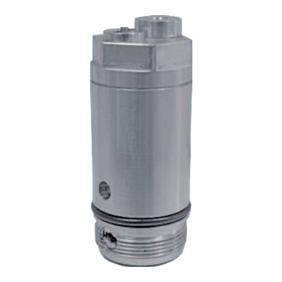
Page 15: 3. Overview/ Functional Description 6 3.1 Overview Of An Oi-Al-Sr
3. Overview/ Functional Description 3. Overview/ functional description 3.1 Overview: OI-AL-SR metering device 3.2 General system description see Fig. 2 Overview, Fig. 1 Single-line centralize d lubrication system Fig. 2 In general a single-line system consists of the following components: pump unit (1), relief valve (2), main lubrication line (3), as well as pre-lubrication metering devices (OI-AL-SR) (4). -
Page 16: 3.3 Functioning Of The Oi-Al-Sr
3. Overview/ Functional Description 3.3 Functioning of the OI-AL-SR position by its pressure spring. The check Lubricating stage (metering device under led with oil under pressure. Thereby the me- valve (8) prevents the oil in the main line from pressure) tering piston (3) is pressed upwards against flowing back into the provisioning chamber (6). - Page 17 3. Overview/ Functional Description Lubrication stage OI-AL-SR Fig. 3 Pressure relief stage OI-AL-SR Fig. 4 Legend of Figures 3 and 4 P1 Inlet (Oil mainline to pump unit) P2 Outlet (Oil pressure line to lube point) Metering device body Supply piston Metering piston Metering screw Metering chamber...
-
Page 18: Technical Data
4. Technical Data / 5. Delivery, Returns and Storage 4. Technical data 5. Delivery, returns, and storage 5.1. Checking the delivery 5.3. Storage After receipt of the shipment, the product o Ambient conditions: dry and dust-free Technical data must be inspected for damage and for surroundings, storage in a well-ventilated Output: 0.02 cm³/stroke... -
Page 19: Set-Up And Attachment
Only qualified technical personnel may in- The product should be protected against hu- During assembly and during any drilling stall, operate, maintain, and repair the SKF midity and vibration and should be installed work for the base plate, always pay attention... -
Page 20: 12 6.2.1 Attaching Measures, Mounting Bores
6. Assembly 6.2.1 Attaching measures, mounting bores Dimensions for mounting bars Fig. 5 [260] SW 22 Tightening torque 25 Nm ± 10 % [30] [30] [30] [30] [30] [30] [30] M24x1 Ø 25 Minimum assembly dimensions A = Length = length of bar + 40 mm B = Height = height of bar + 65 mm C = Depth... -
Page 21: Assembly Of The Oi-Al-Sr
6. Assembly 6.2.2 Minimum assembly dimensions 6.3 Assembly of the OI-AL-SR 6.4 Routing of the lubrication lines metering devices To ensure enough space for maintenance To ensure troublefree functioning of the works and for any disassembly of the pro- entire centralized lubrication system, when Preconditions: duct, adhere to the minimum assembly The divider bar (or base plate) used for as-... -
Page 22: Venting Of The Oi-Al-Sr Metering Devices
6. Assembly 6.5 Venting of the OI-AL-SR metering devices The tube lines, hoses, shut-off and way val- cant. Unavoidable changes in cross-sections ves, fittings, etc. to be used must be desig- should be done in a smooth manner. To ensure full functioning of the OI-AL-SR ned for the maximum operating pressure of metering devices, these must be primed the pump unit, the admissible temperatures,... -
Page 23: Initial Start-Up
7. Start-up/ 8. Shutdown and Disposal 7. Start-up 8. Shutdown and disposal 8.1 Temporary shutdown ATTENTION The product can also be returned to the Observe the information by the machine To temporarily shut down the pre-lubricati- manufacturer for disposal, in which case the manufacturer regarding the lubricants to on metering device OI-AL-SR it is necessary customer is responsible for reimbursing the... -
Page 24: Maintenance
9. Maintenance 9. Maintenance 9.1 General The pre-lubrication metering device of To ensure proper functioning the metering ATTENTION the OI-AL-SR product series works free of device and all connections and ports should maintenance. Still the following points have be checked for tight seat. If necessary, the Make sure to use original Lincoln spare to be observed. -
Page 25: 10.1 Start-Up, Product And System Failures
10. Troubleshooting 10. Troubleshooting 10.1 Start-up, product and system failures The following tables give an overview on possible malfunctions and their causes. If it is not possible to remedy a malfunction Elimination Malfunction Cause with the help of these tables, please contact o Insufficient •... -
Page 26: Accessories
11. Accessories 11. Accessories 11.1 Divider bars and closure screws Divider bars Overview over divider bars with the maximum number of OI-AL-SR metering devices Fig. 6 Closure screw Material: AlCuMgPb F37 DIN 1796 Tightening torque 25 Nm ± 10 % Designation Measure Measure Order No [mm]... -
Page 27: 11.2 Base Plate
11. Accessories 11.2 Base plate Accessory Optional base plate Fig. 7 Material: AlMgSi1 F28-32 AlCuMg1 F28 Designation Order number Optional base plate for E-E (1 : 1) up to 40 OI-AL-SR pre-lubrication metering devices 447-71899-1 0,9 x 45° Option: closure screw M24x1 447-71898-1 Other base plates on request. - Page 28 A global presence provides SKF customers uniform quality standards and worldwide product availability. Important information on product usage All products from SKF may be used only for their intended purpose as described in this brochure and in any instructions. If operating instructions are supplied with the products, they must be read and followed.
Need help?
Do you have a question about the MonoFlex OI-AL-SR and is the answer not in the manual?
Questions and answers