Table of Contents
Advertisement
Quick Links
Advertisement
Table of Contents

Related Manuals for SKF SMBM-X


Summary of Contents for SKF SMBM-X
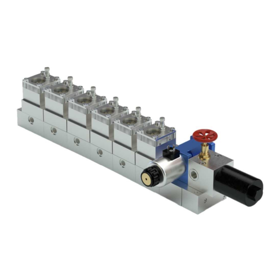
- Page 1 Operating Instructions Flow Limiters SMBM-X and SMBM-V EEX Created on: 16-03-2022 Document no.: 951-180-090-EN Version: Read these instructions before installation or start-up of the product and keep them readily available for consultation.
-
Page 2: Directive 2014/34/Eu, Annex X
It can be labeled by the constructor by some kind of designation marking or coding that is preferred for the system. For SKF, this identification is performed by the blue connection cable that belongs to the signal transmitter. -
Page 3: 2014/34/Eu
SMBM flow limiters without electrical attachments The ignition hazard analysis conducted in accordance with EN 80079-36 / -37 found that SKF flow limiters of the series SMBM without electrical attachments do not constitute own potential sources of ignition. They consequently do not fall under the scope of Directive 2014/34/EU and thus do not bear explosion protection marking. -
Page 4: Masthead
Training www.skf.com/lubrication We conduct detailed training in order to enable maximum safety and efficiency. We recommend taking advantage of this training. Berlin Plant For further information, contact your authorized SKF dealer or Motzener Strasse 35/37 the manufacturer. 12277 Berlin Germany Tel. -
Page 5: Table Of Contents
1.25.4 Instruction and qualification obligations ..... 12 and signal transmitter ............40 1.26 Explosion protection marking according to Directive 6.3.6 Filter unit for SMBM-X ..........40 2014/34/EU ................. 12 6.3.7 Base plates for SMBM-X ......... 41 1.27 Residual risks ..............13 6.4 Assembly drawings SMBM-V .......... - Page 6 9.1 Maintenance for flow limiters ..........57 9.2 Maintenance schedule ............57 9.3 Changing the plug-in nozzle SMBM ........58 9.3.1 Changing the plug-in nozzle SMBM-X ....58 9.3.2 Changing the plug-in nozzle SMBM-V ....58 9.4 New mounting or replacement of a flow limiter module while retaining the base plate module ........
-
Page 7: Safety Alerts, Visual Presentation, And Layout
1. Instruction steps: These indicate a chronological sequence Safety alerts, visual presenta- of instruction steps. The numbers of the steps are in bold and are followed by a period. If a new activity follows, the num- tion, and layout bering starts again at <1.= –... -
Page 8: Safety Instructions
Only original • If protective and safety equipment has to be dismantled, it SKF spare parts and SKF accessories may be used. must be reassembled immediately after finishing the work, • Any unclear points regarding proper condition or correct as- and then checked for correct function. -
Page 9: Foreseeable Misuse
Operator • Use in potentially explosive dusts whose minimum ignition A person competent due to training, knowledge, and experience temperature and glow temperature are less than 150% of the to execute the functions and activities associated with normal maximum surface temperature. •... -
Page 10: Notes On Ce Marking
1.16 Assembly, maintenance, fault, re- pair Prior to the start of this work, all relevant persons must be noti- Type plate of the SMBM-X fied of it. At a minimum, the following safety measures must be taken before any work is done: Fig. -
Page 11: Special Safety Instructions Regarding Explosion Protection
• Unauthorized modifications. • The ignition temperature of the lubricant must lie at least • Use of non-original SKF spare parts / components. 50 K over the maximum admissible surface temperature of • Non-observance of these instructions and other applicable the components. -
Page 12: Briefing Of External Technicians
1.23 Briefing of external technicians 1.25.3 Provision of necessary information • The operator must make the instructions required for the re- Prior to commencing the activities, external technicians must be spective activity accessible to all people commissioned with informed by the operator of the company safety provisions, the operation, maintenance and repairs. -
Page 13: Residual Risks
1.27 Residual risks Table 1 Residual risks Residual risk Possible in lifecycle Avoidance / Remedy Personal injury / property damage due A B C G H K • Unauthorized persons must be kept away to falling of hoisted parts • Personnel are not permitted to stand under hoisted parts •... -
Page 14: Residual Atex Risks
1.28 Residual ATEX risks Table 2 Residual hazards when operating in a potentially explo- Avoidance / Remedy sive atmosphere Use in a potentially explosive atmosphere without checking • Check the equipotential bonding for continuity before first start-up, af- equipotential bonding for electrical continuity ter every repair, and additionally at regular intervals defined by the op- erator Use of non-standard-compliant varnishing of grounded... -
Page 15: Lubricants
2.2 Selection of lubricants • NBR, FPM, ABS, PA, PU 2.4 Temperature properties SKF Lubrication Systems considers lubricants to be an element of system design. The selection of a suitable lubricant should The lubricant used must be suitable for the specific operating reasonably be made during the design of the machine and temperature of the product. -
Page 16: Overview, Functional Description
3. Overview, functional description 3.1 Type identification code of flow limiters of series SMBM 3.1.1 Definition of the type and design S M B M - V 1 1 C S 0 2 5 - E E X Component designation: SMB Flow limiter Type: Modular design... -
Page 17: Definition Of The Electrical Port And The Plug-In Nozzles
Connection cable with straight plug with angle plug, without cable with straight plug, without cable Plug-in nozzle index: 3-digit code of the plug-in nozzles for the SMBM-X ) see table 3 3-digit code of the plug-in nozzles for the SMBM-V ) see table 4... - Page 18 Overview of the flow limiter SMBM-X version (Single-Flow) Fig. 4 Flow limiter SMBM-X Legend: 1 SMBM-X00 (code in the type identification code: 00) 2 SMBM-X22 (code in the type identification code: 22) 3 SMBM-X01, SMBM-X02 oder SMBM-X03 (code in the type identification code: 01, 02 or 03)
- Page 19 Overview of the flow limiter SMBM-V version (Dual-Flow) Fig. 5 Flow limiter SMBM-V Legend: 1 SMBM-V00 (code in the type identification code: 00) 2 SMBM-V22 (code in the type identification code: 22) 3 SMBM-V01, SMBM-V02 or SMBM-V03 (code in the type identification code: 01, 02 or 03) 4 SMBM-V11, SMBM-V12 or SMBM-V13 (code in the type identification code: 11, 12 or 13) 5 SMBM-V51, SMBM-V52 or SMBM-V53 (code in the type identification code: 51, 52 or 53) 6 Changeover valve...
-
Page 20: Plug-In Nozzle Table Smbm-X D
Table 3 3.2 Plug-in nozzle table SMBM-X D Nozzle in- Nominal volumetric flow Table 3 [l/min] [pts/min] Item number Nozzle in- Nominal volumetric flow <Content> [l/min] [pts/min] Item number 4.18 8.83 24-0455-2610 4.37 9.24 24-0455-2611 <Content> 4.57 9.66 24-0455-2612 0.08 0.17... -
Page 21: Plug-In Nozzle Table Smbm-V With D And D
3.3 Plug-in nozzle table SMBM-V with D and D Table 4 Nozzle Nominal volumetric flow Item number index [l/min] D [pts/min] D Plug-in nozzle D Plug-in nozzle D 0.12:0.47 0.25:0.99 24-0455-2575 24-0455-2582 0.12:0.56 0.25:1.18 24-0455-2575 24-0455-2583 0.15:0.65 0.32:1.37 24-0455-2576 24-0455-2584 0.20:0.79 0.42:1.67 24-0455-2577... -
Page 22: Ordering A Complete Flow Limiter Assembly Group
SMBM-NNNNN. The base plates for the assembly group must be ordered separately. NOTICE Prevent malfunctions It is not permitted to use a mixture of SMBM-X and SMBM-V on a single base plate, because otherwise the flow limiter SMBM-X will not be supplied with oil during the valve setting for start-up operation. -
Page 23: Application
3.6 Functional description See Figure and Figure The SMBM flow limiters are individual modules for setup on base plates. Functionality for the two series (SMBM-X and SMBM-V) is identical. The total volumetric flow Q , which is supplied to a flow limiter... - Page 24 Fig. 7 Functional diagram SMBM-X Table 6 Legend to Fig. 7 Item Designation Inlet volume flow Q Outlet volumetric flow Q Inlet pressure p upstream of D Control piston SK Plug-in nozzle D (nonadjustable restrictor) Variable restrictor D Inner pressure p...
- Page 25 Fig. 8 Functional diagram SMBM-V Table 7 Legend to Fig. 8 Item Designation Inlet volume flow (5) Q )/starting state and inlet volume flow (6) Q )/operating state Outlet volumetric flow Q Inlet pressure p upstream of D Control piston SK Plug-in nozzle D (nonadjustable restrictor) Plug-in nozzle D...
-
Page 26: Example Of A Circulating-Oil- Lubrication System With Flow Limiter Of Series Smbm-X
(4) are closed by the valves (3). Example of a circulating-oil lubrication system with SMBM-X The pump (1) now delivers the lubricant to the main pressure line (2). From here it travels through the oil filters (6) to the flow... -
Page 27: Example Of A Circulating-Oil- Lubrication System With Flow Limiter Of Series Smbm-V
< NOTICE Avoiding malfunctions It is not permitted to utilize a mixture of SMBM-X and SMBM-V on the same base plate, because otherwise the SMBM-X flow limiter would not be supplied with oil while the valve is positioned for... -
Page 28: Technical Data
Approx. 1.1 kg / with gear wheel-type flow indicator approx. 1.3 kg • Base plates for 1 to 6 flow limiters SMBM-X- see section 6.3.7 / SMBM-V- see section 6.4.8 • Attachment parts and monitoring See sections 4.2 to 4.5... -
Page 29: Pulse Generator 2340-00000091 For Gear Wheel Indicator
4.2 Pulse generator 2340-00000091 for NOTE gear wheel indicator See the sensor's EU type examination certificate for the relationship between the type of connected circuit, the max- < imum permissible ambient temperature, the surface tem- DANGER perature, and the effective internal reactances. The number Excessive switching voltage hazard of the type examination certificate is entered on the sensor The pulse generator may be used only with an... -
Page 30: Signal Transmitter 24-1072-2125 For Flow Indicator
4.4 Signal transmitter 24-1072-2125 for Table 15 flow indicator Electrical changeover valve 24-1254-3437 Properties/characteristics Values Table 14 <Content> Signal transmitter 24-1072-2125 Thread connection / seal M20x1.5 / NBR Voltage 24 V DC Properties/characteristics Values Max. rated capacity 17 W, at ambient tempera- <Content>... -
Page 31: Plug-In Nozzle Table Smbm-X D
Table 16 4.6 Plug-in nozzle table SMBM-X D Nozzle in- Nominal volumetric flow Table 16 [l/min] [pts/min] Item number <Content> Nozzle in- Nominal volumetric flow [l/min] [pts/min] Item number 3.16 6.68 24-0455-2604 <Content> 3.30 6.97 24-0455-2605 0.08 0.17 24-0455-2574 3.43 7.25... -
Page 32: Plug-In Nozzle Table Smbm-V With D And D
4.7 Plug-in nozzle table SMBM-V with D and D Table 17 Nozzle Nominal volumetric flow Item number index [l/min] D [pts/min] D Plug-in nozzle D Plug-in nozzle D 0.12:0.47 0.25:0.99 24-0455-2575 24-0455-2582 0.12:0.56 0.25:1.18 24-0455-2575 24-0455-2583 0.15:0.65 0.32:1.37 24-0455-2576 24-0455-2584 0.20:0.79 0.42:1.67 24-0455-2577... -
Page 33: Calculation Of The Resulting Oil Volumetric Flow
4.8 Calculation of the resulting oil volumetric flow 4.8.1 Diagram for determination of the nozzle index Fig. 13 Determination of nozzle index 050 to 145 with a differential pressure of 20 bar Legend 1 Viscosity [mm 2 Flow rate [l/min] 3 Nozzle index determined... -
Page 34: Diagram For Determination Of The Correction Factor For The Volumetric Flow Of The Oil
4.8.2 Diagram for determination of the correction factor for the volumetric flow of the oil Fig. 14 Viscosity and pressure correction Legend 1 Nozzle index 2 Viscosity 150 mm /s; Differential pressure 50 3 150 bar 3 Viscosity 300 mm /s;... -
Page 35: Determination Example
4.8.3 Determination example Given: Q = 0.69 l / min (1.46 pts / min) working viscos- ity v = 300 mm /s differential pressure —p = 50 bar (e.g., system pressure 90 bar, back pressure 40 bar) 1 Preselection of the nozzle index -see diagram in Fig. -
Page 36: Delivery, Returns, Storage
5.4 Storage temperature range 5. Delivery, returns, storage For parts not filled with lubricant, the permitted storage tem- 5.1 Delivery perature is the same as the permitted ambient temperature range (see <Technical data=). After receipt of the shipment, it must be inspected for any ship- 5.5 Declaration of decontamination ping damage and for completeness according to the shipping documents. -
Page 37: Assembly
< 6. Assembly CAUTION Slipping hazard 6.1 General information Centralized lubrication systems must always be free of leaks. Leaking lubricant is hazardous. It Only qualified technical personnel may install the products spec- creates a risk of slipping and injury. ified in the instructions. Beware of any lubricant leaking out during as- The product should, to the extent possible, be protected from sembly, operation, maintenance, or repair of cen-... -
Page 38: Assembly Drawings Smbm-X
6.3 Assembly drawings SMBM-X 6.3.2 SMBM-X22 with signal transmitter Fig. 17 6.3.1 SMBM-X00 without gear-type flow in- dicator, without signal transmitter Fig. 16 Flow limiter with signal transmitter, SMBM-X22 Table 19 Flow limiter, SMBM-X00 Minimum mounting dimensions, SMBM-X22 Table 18... -
Page 39: Smbm-X01/X02/X03 With Gear-Type Flow Indicator
6.3.3 SMBM-X01/X02/X03 with gear-type 6.3.4 SMBM-X11/X12/X13 with gear-type flow indicator flow indicator and pulse generator Fig. 18 Fig. 19 Flow limiter with gear-type flow indicator SMBM-X01/X02/X03 Flow limiter with gear-type flow indicator and pulse generator, SMBM-X11/X12/X13 Table 20 Table 21 Minimum mounting dimensions SMBM-X01/02/03 Minimum mounting dimensions SMBM-X11/X12/X13 Designation:... -
Page 40: Smbm-X51/X52/X53 With Gear-Type Flow Indicator And Signal Transmitter
6.3.6 Filter unit for SMBM-X Fig. 20 Fig. 21 Flow limiter with gear-type flow indicator and signal transmit- Filter unit for SMBM-X ter, SMBM-X51/X52/X53 Table 23 Table 22 Minimum mounting dimensions, filter unit SMBM-X Minimum mounting dimensions SMBM-X51/X52/X53 Designation: Dimension Designation: Dimension <Content> <Content>... -
Page 41: Base Plates For Smbm-X
6 Filter unit with shut-off valve (not a part of the filter plate (5), must be ordered separately) 7 Inlet G 1/2 8 Outlets G 3/8 Table 24 Attachment dimensions A/B/C/D for SMBM-X base plates with maximum number of attached modules Dimensions [mm] 1 module 2 modules... - Page 42 Table 25 Weight specifications for SMBM-X base plates with maximum number of attached modules 1 module (base Weight [kg] 2 modules 3 modules 4 modules 5 modules 6 modules module) Connecting plate with base plate(s) for 1.60 2.60 3.60 4.60 5.60...
-
Page 43: Assembly Drawings Smbm-V
6.4.2 SMBM-V22 with signal transmitter 6.4 Assembly drawings SMBM-V Fig. 24 6.4.1 SMBM-V00 without gear-type flow in- dicator, without signal transmitter Fig. 23 Flow limiter with signal transmitter, SMBM-V22 Table 27 Flow limiter, SMBM-V00 Minimum mounting dimensions SMBM-V22 Designation: Dimension Table 26 <Content>... -
Page 44: Smbm-V01/V02/V03 With Gear-Type Flow Indicator, Without Pulse Generator
6.4.3 SMBM-V01/V02/V03 with gear-type 6.4.4 SMBM-V11/V12/V13 with gear-type flow indicator, without pulse generator flow indicator and pulse generator Fig. 25 Fig. 26 Flow limiter with gear-type flow indicator SMBM-V01/V02/V03 Flow limiter with gear-type flow indicator and pulse generator, SMBM-V11/V12/V13 Table 28 Table 29 Minimum mounting dimensionsSMBM-V01/V02/V03 Minimum mounting dimensions SMBM-V11/V12/V13... -
Page 45: Smbm-V51/V52/V53 With Gear-Type Flow Indicator And Signal Transmitter
6.4.5 SMBM-V51/V52/V53 with gear-type 6.4.6 Filter unit for SMBM-V flow indicator and signal transmitter Fig. 28 Fig. 27 Filter unit for SMBM-V Flow limiter with gear-type flow indicator and signal transmit- Table 31 ter, SMBM-V51/V52/V53 Minimum mounting dimensions filter unit SMBM-V Table 30 Designation: Dimension... -
Page 46: Changeover Valve For Smbm-V
6.4.7 Changeover valve for SMBM-V Fig. 29 Changeover valve for SMBM-V Table 32 Minimum mounting dimensions changeover valve SMBM-V Designation: Dimension <Content> T = Width: 80 mm L = Length: 280 mm H = Height: 180 mm All further dimensions - see drawing SMBM-V00... -
Page 47: Base Plates For Smbm-V
6.4.8 Base plates for SMBM-V Fig. 30 Base plates for SMBM-V Legend 1 Base plate for module 1 (base module) 2 Base plate for module 6 3 Base plates for expansion modules (2 to max. 5) 4 Valve plate 5 Changeover valve (not a part of the valve plate (4), must be ordered separately) 6 Connecting plate 7 Filter plate 8 Filter unit with shut-off valve (not a part of the filter plate (7), must be ordered separately) - Page 48 Table 34 Weight specifications for SMBM-V base plates with maximum number of attached modules 1 module (base Weight [kg] 2 modules 3 modules 4 modules 5 modules 6 modules module) Connecting plate and valve plate (without 1.96 2.96 3.96 4.96 5.96 6.96 changeover valve) with base plate(s) for...
-
Page 49: Assembling The Flow Limiters Smbm
3. Carefully place and align the flow limiter on the flanging sur- 6.5 Assembling the flow limiters SMBM face and align its assembly holes with den customer-provided assembly holes. See also Fig. 31 4. Insert hexagon head screws (2x) with washers (2x) in the as- sembly holes and tighten them slightly. -
Page 50: Mechanical Connection Options Smbm
(R 1/2") (6). torque of 30 ± 1 Nm. A switching of the supply connection from right to left can be implemented at the customer site with the SMBM-X flow Fig. 32 Mechanical connection options SMBM-X... - Page 51 Fig. 33 Mechanical connection options SMBM-V...
-
Page 52: Electrical Connection Of Atex Pulse Generator 2340-00000091
The signal transmitter can be used to monitor the volumetric flow within an ATEX-compliant SKF flow limiter. The signal transmitter with integrated floating contact can be used as sim- ple electrical apparatus in accordance with DIN EN 60079-11, Para. -
Page 53: Connection, Signal Transmitter 24-1072-2125 (Connection Type Xs)
6.8.2 Connection, signal transmitter 24- Fig. 36 1072-2125 (connection type XS) See Figure 35 to Figure 37 1.Detach the entire cable socket (1) from the signal transmitter (2). 2. Unscrew the connection socket (3), housing (4), and cable gland (5) with tapered ring (6) out of the cable socket (1). NOTE Connection socket, interior view Observe the maximum clamping limit for the terminal... -
Page 54: Electrical Connection Of Changeover Valve 24-1254-3437
6.9 Electrical connection of changeover Table 37 valve 24-1254-3437 Spare parts/accessories For electrical data of the ATEX 3/2 changeover valve (directional Designation Item number solenoid valve), see Chapter 4.5 <Content> 3/2 changeover valve 24-1254-3437 •Connect directional solenoid valve in accordance with the ter- II 2G Ex e mb IIC T4 Gb minal diagram in Figure 38. -
Page 55: First Start-Up
7. First start-up To ensure safety and functionality, the person specified by the operator is required to perform the following inspections. Any detected deficiencies must be remedied prior to initial start-up. The correction of deficiencies must be done exclusively by a specialist competent and authorized to do so. -
Page 56: Operation
8. Operation SKF products operate largely automatically. The activities required during normal operation are limited pri- marily to cleaning of the exterior of the product if contaminated. < NOTICE Avoiding malfunctions Safe operation of the flow limiters is ensured only when clean lubricating oil is being supplied. -
Page 57: Maintenance And Repair
must always be determined by the operator according to the 9. Maintenance and repair operating conditions and the local conditions and regularly re- viewed and adapted where necessary. Careful and regular maintenance is required in order to detect and remedy possible faults in time. The operator must always In particular with maintenance and repair work, the following determine the specific intervals according to the operating con- safety measures must implemented at a minimum:... -
Page 58: Changing The Plug-In Nozzle Smbm
CAUTION Spring tension The control piston is under spring tension 9.3.1 Changing the plug-in nozzle SMBM-X See Figure 39 • Interrupt the oil feed to the flow limiter (1). • Loosen the plug screw (2) using a hexagon socket screw key Changing the plug-in nozzle SMBM-X (WAF 12) and remove it together with the packing ring (2a). - Page 59 < Fig. 40 CAUTION Burn injury hazard Escaping oil is possibly hot • Remove control piston (5) with plug-in nozzles (2/4) (D and pressure spring. < NOTICE Risk of mix-ups When reinstalling the plug-in nozzles, take care to ensure they are not mixed up! For plug-in nozzle selection, see Chapter 4.7 .
-
Page 60: New Mounting Or Replacement Of A Flow Limiter Module While Retaining The Base Plate Module
• Place a new O-ring (6) in the groove of the borehole (7). < CAUTION • Carefully place the SMBM-X module (10) on the flanging area Burn injury hazard of the base plate module (3). • At the SMBM-X module, put the hexagon socket screw (8) Escaping oil is possibly hot (M8 x 100, WAF 6) in place and tighten it slightly. -
Page 61: Expanding An Existing Flow Limiter Assembly Group By Adding An Smbm Module
• Carefully detach the dummy module (2) from the base plate 9.4.3.1 General procedure module (3) and set it to one side along with the two screws • Interrupt the oil feed to the flow limiter. (1) and mounted packing rings (6). •... - Page 62 (tapered thread). • Place a new packing ring (6) in the groove of the borehole (7). • Carefully place the SMBM-X module on the flanging area of the base plate module (3). • On the SMBM-X module, put the hexagon socket screw (8) (M8 x 100, SW 6 mm) in place and tighten it slightly.
- Page 63 2 Dummy module 3 Base plate module 4 Plug screw (SMBM-X only) 5 Borehole 6 Packing ring (SMBM-X) / 6a packing rings (SMBM-V) 7 Borehole 8 Hexagon socket screw M8 x 100mm 9 Hexagon socket screw M8 x 40mm 10 SMBM-X / SMBM-V module...
- Page 64 Fig. 42 Expansion of an existing assembly to include an SMBM module Legend 1 Fastening screws (1a/1b) 2 Flow limiter assembly group 3 Plug screw 4 Connecting plate 5 Hexagon socket screw M6 x 40mm (2x) 6 Filter unit with filter plate 7 Hexagon socket screw M6 x 60mm (2x) 8 Spacer screws M12 x 1.5mm (2x per module) 9 Hexagon socket screw M6 x 65mm (2x per module)
-
Page 65: Cleaning
10.3 Interior cleaning The interior normally does not need to be cleaned. The interior of the product must be cleaned if incorrect or contaminated lubricant is accidentally filled. Please contact SKF Customer Service. 10.4 Cleaning of the pulse generator If the active sensor surface becomes contaminated with lubri-... -
Page 66: Faults, Causes, And Remedies
The described component is pressurized during operation. Depressurize the component before The following table provides an overview of possible malfunc- starting maintenance work tions and their causes. Contact the SKF Service department if you cannot remedy the malfunction. < WARNING... -
Page 67: System Malfunctions With Effects On The Flow Limiter
11.2 System malfunctions with effects on the flow limiter Table 46 Malfunction Cause Remedy • System pressure too low • Check the system pressure • Plug-in nozzle size too small • Check the selection of the plug-in nozzle against the selection table and insert the correct nozzle •... -
Page 68: Repairs
• Depressurize the signal transmitter (1). 12. Repairs 12.1.1 with defective signal transmitter < • Unscrew the cable socket (2) from the signal transmitter (3). WARNING • Attach box wrench (WAF 32) to the signal transmitter, detach Risk of injury the signal transmitter. -
Page 69: Mounting Or Replacement Of The Pulse Generator 2340-00000091
12.2.3 Carrying out a function check 12.2 Mounting or replacement of the • Activate the flow limiter system. pulse generator 2340-00000091 See Fig. 44 Pulse generator 2340-00000091 NOTE Requirement: Supply voltage must be applied to the pulse < generator. The gears in the gear chamber must rotate. With NOTICE correct assembly and rotating gears, the diode (11) on the Assembly / open lid thread... -
Page 70: Shutdown, Disposal
13. Shutdown, disposal 13.1 Temporary shutdown Temporary shutdown is performed by: • Switching off the main machine • Depressurizing the signal transmitter 13.2 Permanent shutdown, disassembly Permanent shutdown and disassembly of the product must be planned properly by the operator and conducted in compliance with all applicable requirements. -
Page 71: Spare Parts
The spare parts groups are used exclusively as replacement Designation Figure for defective parts identical in construction. Modifications to existing products by the use of spare parts are therefore not <Content> permitted. SMBM-X00 Fig. 45 SMBM-X22 SMBM-X01/02/03 SMBM-X11/12/13 SMBM-X51/52/53 Structure of an SMBM-X... - Page 72 Table 48 Table 50 SMBM-V modules Seal set for base module Item number 24-0404-2645 Designation Figure Comprised of Pcs. Item number/type Figure <Content> <Content> SMBM-V00 Copper sealing DIN7603-A21X26-CU ring Copper sealing DIN7603-A17X21-CU ring SMBM-V22 O-ring 12x2 WVN532-12x2 Table 51 Seal set for expansion module SMBM-V01/02/03 Item number 24-0404-2646 Comprised of...
- Page 73 <Content> Stop screw with 24-1821-2040 O-ring 16x2 WVN532-16x2 O-ring O-ring for stop screw 1 96-9019-0062 Throttle bushing 24-0220-2011 SMBM-X with O-rings Throttle bushing 24-0220-2022 SMBM-V with O-rings and retaining Table 55 ring Gear with 24-1858-2218 Seal set for changeover valve...
-
Page 74: Accessories
14.2 Accessories Table 59 Cable boxes with cable for ATEX inductive pulse genera- Item number 2340-00000091 Designation Pcs. Item number <Content> Cable box, straight, with 5 m length 24-1882-5005 Type V1-G-N-5M-PUR Cable box, angled, with 15 m length 24-1882-5016 TYPE V1-W-N-15M-PUR Table 60 Fitting tool for check valve Item number 24-2104-2049... - Page 75 ® SKF is a registered trademark of the SKF Group. eLube is a trademark of the SKF Group. © SKF Group 2022 Reprint or reproduction of the contents of this information - even in part - is permitted only with SKF's prior written consent.
Need help?
Do you have a question about the SMBM-X and is the answer not in the manual?
Questions and answers