
Subscribe to Our Youtube Channel
Related Manuals for SKF Linkoln DU1


Summary of Contents for SKF Linkoln DU1
- Page 1 Assembly instructions Pressure-controlled change-over device following machinery directive 2006/42/EC Type DU1 951-171-011-EN 2017/11/23 Version 03...
-
Page 2: Ec Declaration Of Incorporation Following Machinery Directive 2006/42/Ec, Annex Ii, Part 1 B
EC Declaration of incorporation EC Declaration of incorporation following machinery directive 2006/42/EC, annex II, part 1 B The manufacturer, SKF Lubrication Systems Germany GmbH, Walldorf Facilities, Heinrich-Hertz-Str. 2-8, DE - 69190 Walldorf, hereby declares that the partly completed machinery Designation:... - Page 3 The instructions do not contain any infor- The instructions following machinery direc- mation on the warranty. This can be found in SKF Lubrication Systems Germany GmbH tive 2006/42/EC are part of the described our general terms and conditions. products and must be kept at an accessible Americas / Asia / Pacific location for further use.
-
Page 4: Table Of Contents
Table of contents Table of contents EC Declaration of incorporation following machinery directive 2006/42/ EC, annex II, part 1 B ...................2 Explanation of symbols and signs ...............5 Delivery, returns, and storage ............ 24 Safety instructions .................7 Delivery ....................24 General safety instructions ..............7 Returns ....................24 General behaviour when handling the product ........ -
Page 5: Explanation Of Symbols And Signs
Explanation of symbols and signs Explanation of symbols and signs Please read these instructions thor- Symbols You will find these symbols, which warn of oughly and heed the warning and safety specific dangers to persons, material assets, Symbol Meaning notes. Please observe the warning and or the environment, next to all safety in- safety notes and exercise particular cau- structions in these operating instructions. - Page 6 Explanation of symbols and signs Abbreviations and conversion factors Abbreviations regarding Ounce approx. approx. pounds per square inch °C degrees Celsius relative humidity cu.in cubic inch second dB (A) Sound pressure level sq.in. square inch i.e. that is etc. et cetera e.g.
-
Page 7: Safety Instructions
1. Safety instructions 1. Safety instructions 1.1 General safety instructions 1.2 General behaviour when handling the product The owner must ensure that safety informa- ○ Safety-related protective and emergency ○ The product may be used only in aware- tion has been read by any persons entrusted devices must not be removed, modified with works on the product or by those per- ness of the potential dangers, in proper... -
Page 8: Qualified Technical Personnel
The definition Product training can also be performed by of qualified personnel and the prohibition SKF in exchange for costs incurred. against employing non-qualified personnel are laid down in DIN VDE 0105 and IEC 364. Relevant country-specific definitions of... -
Page 9: Electric Current Hazard
1. Safety instructions 1.4 Electric current hazard 1.5 System pressure hazard 1.6 Operation The following must be observed during WARNING WARNING commissioning and operation. ○ All information within this manual and Electric shock System pressure Working on products not discon- The product is pressurized during the information within the referenced nected from the power supply may... -
Page 10: Assembly, Maintenance, Malfunctions, Modification, Shutdown, Disposal
For ranges going beyond the specified ones, ○ Assemble the product only outside of the the electromotive change-over device type SKF spare parts only. operating range of moving parts, at an EM-U3 can be used in combination with ○ Any malfunctions which may affect safety adequate distance from sources of heat end-of-line pressure switches. -
Page 11: Foreseeable Misuse
1. Safety instructions 1.9 Foreseeable misuse 1.10 Disclaimer of liability 1.11 Other applicable documents Any usage of the product differing from The manufacturer shall not be held respon- In addition to these instructions, the fol- the aforementioned conditions and stated sible for damages caused by: lowing documents must be observed by the purpose is strictly prohibited. -
Page 12: Residual Risks
1. Safety instructions 1.12 Residual risks Residual risks Remedy Life cycle transport, assembly, start-up, operation, malfunction, troubleshooting, repair, maintenance, shutdown, disposal ○ No people may remain under suspended loads. Keep unauthorized persons away. Secure suspend- Dropping of lifted parts or tools ed loads using suitable hoisting equipment (e.g. - Page 13 1. Safety instructions Residual risks Remedy Life cycle transport, assembly, start-up, operation, malfunction, troubleshooting, repair, maintenance, shutdown, disposal Contamination of the environment with lu- ○ Dispose of the parts following the relevant legal/ operational regulations bricant and wetted parts...
-
Page 14: Lubricants
CLP Regulation EC 1272/2008 annex I, lubrication task is made by the machine or part 2-5 may be filled into SKF centralized system manufacturer and/or the operator of lubrication systems and components and the machine or system in cooperation with delivered and/ or distributed with such sys- the lubricant supplier. -
Page 15: Approved Lubricants
NOTICE using lubricants that meet the specifica- tions in the technical data. Depending on the If required SKF can help customers to Only lubricants approved for the product product design, these lubricants may be oils, select suitable components for feeding the may be used. -
Page 16: Lubricants And The Environment
2. Lubricants 2.4 Lubricants and the environment It is important to note that lubricants are WARNING environmentally hazardous, flammable substances that require special precaution- Risk of slipping and injury ary measures during transport, storage, Leaking lubricant is hazardous due and processing. Consult the safety data to the risk of slipping and injury. -
Page 17: Overview, Functional Description
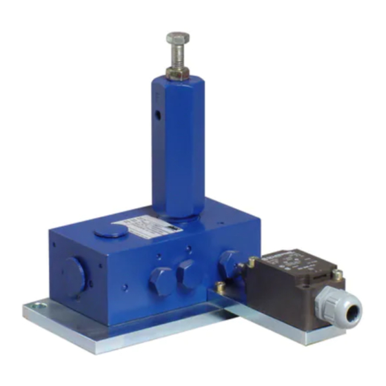
3. Overview, functional description 3. Overview, functional description Overview Fig. 1 In its principle the change-over device corre- sponds to a pressure-controlled 4/2-way valve. It alternately dispenses the lubricant fed by the pump to one of the two main lines while the other main line is connected to the return line connection of the pump. - Page 18 3. Overview, functional description Overview Fig. 2 Lubricant pressure actuates the pistons of the connected dual-line metering devices. The corresponding lubrication points are provided with metered lubricant volumes. As soon as all pistons in the metering devices have reached their final position, pressure in the main line (7), in the change-over device and in the pressure line (5) rises until it overcomes the force of the spring that presses the valve...
- Page 19 3. Overview, functional description Change-over device DU1 is available in 4 different versions: Type Part no. DU1-G on base plate 617-28683-1 DU1-GK 617-28619-1 with indicator pin mounted on base plate DU1-GKS 617-28620-1 with indicator pin and limit switch mounted on base plate DU1-GKN 617-36148-9 with indicator pin and proximity switch mounted on base plate...
-
Page 20: Technical Data
4. Technical data 4. Technical data 4.1 General technical data Flow rate 14 dm³/h max. min. 140 bar Change-over pressure 350 bar max. Factory setting 170 bar Operating pressure 350 bar max. Connection thread G 1/2 Lubricating oils as of 60 mm²/s at +40°C Flow media Grease up to NLGI class 3 (depending on the operation temperature) Operation temperature... -
Page 21: Notes Related To The Type Identification Plate
4. Technical data 4.2 Notes related to the type identifica- 4.3 Notes related to the CE marking tion plate CE marking is effected following the require- ments of the applied directives: The type identification plate states impor- ○ 2014/30/EU Electromagnetic tant characteristics such as type designa- compatibility tion, order number, etc. -
Page 22: Limit Switch
4. Technical data 4.4 Limit switch Part number 236-13262-4 16,5 R 8,5 Design Following EN 50041 Electrical data Version of the switching element (NO) contact, (NC) contact Switching principle Positively driven (NC) contact Number of auxiliary contacts Number of safety contacts 30,5 Rated impulse voltage 6 kV... -
Page 23: Proximity Switch
4. Technical data 4.5 Proximity switch Part number 234-10812-8 General data Function of switching element PNP normally open contact Rated operating distance 2 mm Installation flush Output polarity Secured switching distance 0 to 1.62 mm Reduction factor Mechanical data Reduction factor Reduction factor Type of connection M12 x 1 plug;... -
Page 24: Delivery, Returns, And Storage
5.3 Storage 5.2 Returns The products are packaged following the Clean all parts and pack them properly SKF products are subject to the following standard commercial practice according to before returning them. Protect the product storage conditions: the regulations of the recipient's country. -
Page 25: Installation
6. Installation 6. Installation 6.1 General information 6.2 Attachment Only qualified technical personnel may Protect the product against humidity (ob- CAUTION install, operate, maintain, and repair the serve IP protection class) and vibration and products described in these Instructions. install it in an easily accessible position to Electric shock Qualified technical personnel are persons ensure all other installations can be carried... -
Page 26: Electrical Connection
6. Installation 6.3 Electrical connection CAUTION Personal injuries caused by in- correct installation Assembly and installation of elec- trical devices may be carried out by a commissioned and qualified electrician only! Observe the relevant standard engineering practice and the re- spective occupational health and safety acts. -
Page 27: Start-Up
7. Start-up 7. Start-up After connection of the tube lines the change-over device is ready for operation. The start-up is effected by switching on the superior machine. -
Page 28: Operation, Shutdown And Disposal
8. Operation, shutdown and disposal 8. Operation, shutdown and disposal Settings 8.2 Shutdown and disposal NOTICE • Secure the new setting by means of counter nut (11). Shutdown is effected by switching the supe- Property damage rior machine or vehicle off. Reduce the change-over pressure: The change-over pressure must not ex- In case of final shutdown follow the appli-... -
Page 29: Maintenance, Cleaning And Repair
9. Maintenance, cleaning and repair 9. Maintenance, cleaning and repair 9.2 Maintenance 9.1 General information • Provided that clean lubricant is supplied only, the change-over device does not require any particular care. CAUTION Electric shock 9.3 Cleaning Prior to performing any repair •... -
Page 30: Troubleshooting
10. Troubleshooting Troubleshooting In case of any malfunction, first of all, check whether the pump achieves the full pressure. Fault Possible causes of the fault/ identification Remedy ○ Worn change-over piston Change-over device does not change over, ○ Replace change-over device Note: Lubricant is supplied to the no pressurization of the system pump via the return line connection... -
Page 31: Spare Parts
11. Spare parts Spare parts The spare parts of the DU1 may be used exclusively for replacement of identical defective parts. Modifications with spare parts on existing change-over devices are not allowed. Spare parts Fig. 5... - Page 32 11. Spare parts Item Designation Qty. Part number Change-over housing assy with pin (DU1-GK and GKS) 517-32043-1 Note Change-over housing without pin (DU1-G) 517-32044-1 Item numbers, see Fig. 5 Hexagon closure screw G1/4 303-19666-1 Stop screw 417-24361-1 Indicator pin 301-17341-1 Sealing ring 2.8x7x1.5 306-17800-1 Groove ring 3x7x5x3.5...
- Page 33 11. Spare parts Item Designation Qty. Part number For change-over device DU1-GKN only: Note Proximity switch 10-30 VDC M12 PNP SN = 2 mm 234-10812-8 Item numbers, see Fig. 8 Mounting block for sensor M12x1 417-73711-1 Hexagon socket head screw 8.8 M5 X 45 C 201-12017-4...
-
Page 34: Dimensional Drawings
12. Dimensional drawings Dimensional drawings DU1-GKS Fig. 7 DU1-GK Fig. 6... - Page 35 12. Dimensional drawings DU1-GKN Fig. 8...
- Page 36 951-171-011-EN 2017/11/13 Version 03 SKF Lubrication Systems Germany GmbH Walldorf Facilities Heinrich-Hertz-Str. 2-8 DE - 69190 Walldorf Phone: +49 (0) 6227 33-0 Fax: +49 (0) 6227 33-259 E-mail: Lubrication-germany@skf.com www.skf.com/lubrication...
Need help?
Do you have a question about the Linkoln DU1 and is the answer not in the manual?
Questions and answers