
Related Manuals for pyroscience PICO-O2-SUB


Summary of Contents for pyroscience PICO-O2-SUB
- Page 1 -SUB Pico-O OEM Fiber-Optic Oxygen Meter MANUAL PyroScience GmbH www.pyroscience.com...
- Page 2 Pico-O2-SUB | Manual -SUB Pico-O OEM Fiber-Optic Oxygen Meter Document Version 1.08 The Pico-O2-SUB is released by: PyroScience GmbH Kackertstr. 11 52072 Aachen Germany Phone +49 (0)241 5183 2210 +49 (0)241 5183 2299 Email info@pyroscience.com www.pyroscience.com Registered: Aachen HRB 17329, Germany...
-
Page 3: Table Of Contents
4.2 Using the software Pyro Developer Tool ................15 Option 3: Simplified Custom Integration ................16 5.1 Configuring the Module using PyroScience Software ........... 16 5.2 Electrical Connector for Custom Integration ..............16 5.3 Configuration of the Serial Interface ..................17 5.4 Communication Protocol ...................... - Page 4 Pico-O2-SUB | Manual 5.4.13 #RDUM – Read User Memory ..................25 5.4.14 #WRUM – Write User Memory .................. 25 5.4.15 #ERRO – Response if Error Occurred ..............26 5.5 Available Implementations of Communication Protocol ..........27 Option 4: Advanced Custom Integration ................28 Technical Drawing ........................
-
Page 5: Introduction
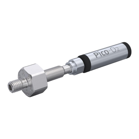
Pico-O2-SUB | Manual INTRODUCTION The Pico-O2-SUB (Item No. PICO-O2-SUB) is an OEM solution for fiber-optic oxygen measurements under water. It is designed for integration into custom-made underwater housings. The Pico-O2-SUB consists of three parts: Our standard Pico-O2 OEM (Pico-O2) module, a pressure stable optical connector (SubPort) for connecting optical sensors and an adapter. - Page 6 Windows PC (see chapter 4). Option 3: A simplified custom integration of the module can be realized by adjusting the settings and performing sensor calibrations using the PyroScience software Pyro Workbench or Pyro Developer Tool (requires the encoded USB interface cable PICO-USB).
-
Page 7: Overview
Pico-O2-SUB | Manual OVERVIEW Figure 2 provides an overview of the Pico-O2. The front provides the port for connecting an optical fiber used for read-out of optical oxygen sensors, as well as solder points for an external temperature sensor enabling automatic temperature compensation. -
Page 8: Optical Port For O2 Sensors
Pressure tests of the whole assembly prior to deployment are strongly advised. Optical port for O2 sensors The Pico-O2-SUB is compatible with special Pyro Science fiber-optic sensors for underwater applications designated by the appendix ‘-SUB’ in the item number. An index matching liquid inside the connector enhances the sensor signals. -
Page 9: External Temperature Sensor
Pico-O2-SUB | Manual Figure 4 Connecting sensors to the SUB port For more detailed information on handling, maintenance, calibration and measurements of the oxygen sensors, information on calibration, please refer to the oxygen sensor manual for more information. External temperature sensor The signal of oxygen sensors is temperature dependent, which can be automatically compensated. -
Page 10: Status Led
Pico-O2-SUB | Manual The Pt100 temperature sensor has to be soldered to the 4 solder pads at the front of the module (Figure 5). For short distances (e.g. 10 cm) a simple 2-wire connection might be sufficient. For this, it is important to shortcut the outer with the inner solder pads as indicated in Figure 4. -
Page 11: Usb Interface Cable
For the operation of Pico-O2 with a Windows PC, a coded USB interface cable (item no. PICO-USB) is available from PyroScience. It includes a license for the comfortable logger software Pyro Workbench and the software Pyro Developer Tool. Especially for initial testing purposes this software packages can speed up OEM-developments significantly. -
Page 12: Option 1: Operating The Module With Pyro Workbench
Pico-O2-SUB | Manual OPTION 1: OPERATING THE MODULE WITH PYRO WORKBENCH For initial evaluation purposes the module can be operated with the simple and customer-friendly software Pyro Workbench, which is typically used by end-users. This software offers comfortable settings and calibration wizards, as well as advanced logging features. -
Page 13: Using The Software Pyro Workbench
Pico-O2-SUB | Manual • connect the USB plug to an USB port of the PC. The status LED of the Pico-O2 should flash shortly indicating the correct startup of the module. • Start the Pyro Workbench software. Using the software Pyro Workbench Please refer to the Pyro Workbench manual for general operation instructions for the software (available on our website). -
Page 14: Option 2: Operating The Module With Pyro Developer Tool
Pico-O2-SUB | Manual OPTION 2: OPERATING THE MODULE WITH PYRO DEVELOPER TOOL For advanced evaluation purposes the module can be operated with the software Pyro Developer Tool. It offers simple settings and calibration procedures, as well as basic logging features. Furthermore, additional advanced settings offer full control on all features of the module. -
Page 15: Using The Software Pyro Developer Tool
Pico-O2-SUB | Manual • connect the USB plug to an USB port of the PC. The status LED of the Pico-O2 should flash shortly indicating the correct startup of the module. • Start the Pyro Developer Tool software. Using the software Pyro Developer Tool Please refer to the Pyro Developer Tool manual for general operation instructions for the software (available on our website). -
Page 16: Option 3: Simplified Custom Integration
Configuring the Module using PyroScience Software Please install either the Pyro Workbench or the Pyro Developer Tool. Follow chapter 3 or chapter 4, respectively, how to operate the module with the PyroScience software. Adjust the settings and perform the required calibrations of the sensor. -
Page 17: Configuration Of The Serial Interface
Pico-O2-SUB | Manual Figure 6: Electrical connectors of Pico-O2 The pin configuration of the connector X1 is given in Table 2 Table 2: Pin configuration of the connector X1 Name Function Description Power Power supply min. 3.3 VDC max. 5.0 VDC... -
Page 18: Communication Protocol
Pico-O2-SUB | Manual Note: The serial interface of this module is not an RS232 interface. However, the UART interface can be made compatible to RS232 by integrating an appropriate "level shifter electronics". Communication Protocol 5.4.1 General Definitions A command always starts with a specific command header (e.g. MEA, #VERS, #LOGO) optionally followed by several input parameters. -
Page 19: Mea - Trigger Measurement
Pico-O2-SUB | Manual MEA – Trigger Measurement 5.4.2 This command triggers a measurement and returns the results. ↵ Command: MEA˽C˽S↵ ˽R …R Response: MEA˽C˽S˽R Input Parameters: Optical channel number. Set C=1. If in doubt, then set S to 47! This parameter defines the enabled sensor types,... - Page 20 Pico-O2-SUB | Manual dphi m° Phase shift of optical measurement (raw data) Oxygen level in units of μmol/L 0.001 umolar µmol/L (valid only in liquids) 0.001 mbar Oxygen level in units of mbar mbar (valid in gases and in liquids) airSat 0.001 %air...
-
Page 21: Chi - Calibrate Oxygen Sensor At Ambient Air
Pico-O2-SUB | Manual The output parameter ambientLight is a measure how much ambient infrared light is entering the oxygen sensor. In principle, such ambient light is not influencing the oxygen measurement. However, excess ambient light might lead to a saturation of the optical... -
Page 22: Clo - Calibrate Oxygen Sensor At 0% (Anoxic)
Pico-O2-SUB | Manual This command performs 16 repeated optical measurements, and uses the average for the calibration. The total duration for this procedure varies between ca. 3s and ca. 6s depending on the configuration of the module. In order to keep the calibration permanently even after a power cycle, the command SVS must be executed afterwards. -
Page 23: Idnr - Get Unique Id Number
Pico-O2-SUB | Manual Output Parameters: Device ID, identifies the specific device type. For the Pico-O2 the device ID is always 4. Number of optical channels. For the Pico-O2 this value is 1. Firmware version, e.g. R=403 designates firmware version 4.03... -
Page 24: Logo - Flash Status Led
Pico-O2-SUB | Manual serial number of the device). ↵ Example Communication: ↵ Command: #IDNR Response: #IDNR˽2296536137892833272 #LOGO – Flash Status LED 5.4.8 This command lets the status LED flash for 4 times within ca. 1 s. Command: #LOGO↵ Response: #LOGO↵... -
Page 25: Rset - Reset Device
Pico-O2-SUB | Manual 5.4.12 #RSET – Reset Device This command triggers a reset of the device. Command: #RSET↵ Response: #RSET↵ Triggers a reset of the device, as if the device experienced a power cycle. 5.4.13 #RDUM – Read User Memory This command reads values from the user memory registers. -
Page 26: Erro - Response If Error Occurred
This error response is mostly given, if the master did not send the command with the correct communication syntax. The output parameter C represents the general PyroScience error types as given by the following table. Note: Warnings and errors directly related to the sensor measurements (e.g. a broken Pt100 temperature sensor, or a "worn out"... -
Page 27: Available Implementations Of Communication Protocol
Pico-O2-SUB | Manual An error occurred while parsing the command string. UART Parse The last command should be repeated. UART Rx The command string was not received correctly (e.g. device was not ready, last request was not terminated correctly). Repeat the last command. -
Page 28: Option 4: Advanced Custom Integration
Pico-O2-SUB | Manual OPTION 4: ADVANCED CUSTOM INTEGRATION For advanced custom integration the full USB/UART communication protocol is available on request, allowing custom software full control on all settings, calibration and measurement features of the module. © PyroScience GmbH... -
Page 29: Technical Drawing
Pico-O2-SUB | Manual TECHNICAL DRAWING The solder pads have 2.54mm pitch. © PyroScience GmbH... -
Page 30: Specifications
Pico-O2-SUB | Manual SPECIFICATIONS General Specifications Dimensions L=59 mm, Ø 17mm (without the optical port) Weight Pico-O2 ca. 20 g Power supply min. 3.3 VDC max. 5.0 VDC Connector plug Phoenix Contact PTSM0,5/4-P-2,5 Power consumption -during operation typ. 10 mA -during deep sleep mode typ. - Page 31 Pico-O2-SUB | Manual Internal Temperature Sensor (located on internal PCB) Resolution 0.02 °C Accuracy +-0.3 °C Range -40 to 125 °C Note: This max. sample rate refers only to the limits of the UART communication. It does not consider the actual response time of the connected optical oxygen sensor or of the temperature sensor.
-
Page 32: Safety Guidelines
Pico-O2-SUB | Manual 1. SAFETY GUIDELINES Before using the Pico-O2-SUB and its sensors, read carefully the instructions and user manuals. In case of problems or suspected damage, do not use the device and mark it to prevent any further use! Consult Pyro Science for advice. There are no serviceable parts inside the device. - Page 33 Pico-O2-SUB | Manual CONTACT PyroScience GmbH Tel.: +49 (0)241 5183 2210 Kackertstr. 11 Fax: +49 (0)241 5183 2299 52072 Aachen info@pyroscience.com Deutschland www.pyroscience.com www.pyroscience.com...
Need help?
Do you have a question about the PICO-O2-SUB and is the answer not in the manual?
Questions and answers