Table of Contents
Advertisement
Quick Links
Advertisement
Table of Contents

Related Manuals for pyroscience Piccolo2


Summary of Contents for pyroscience Piccolo2
- Page 1 Piccolo IBER OPTIC XYGEN ETER ANUAL...
- Page 2 Document Version 2.04 Refers to Pyro Oxygen Logger Software version >3.2 Piccolo2 is manufactured by Pyro Science GmbH Hubertusstr. 35 52064 Aachen Germany Phone +49 (0)241 5183 2210 +49 (0)241 5183 2299 Email info@pyro-science.com Internet www.pyro-science.com Registered: Aachen HRB 17329, Germany...
-
Page 3: Table Of Contents
ABLE OF ONTENT OVERVIEW ................5 SAFETY GUIDELINES .............. 6 INTRODUCTION TO THE PICCOLO2 ......... 8 SOFTWARE INSTALLATION ............ 9 OXYGEN SENSOR TYPES............10 ............... 10 OBUST ROBE ............... 11 IPPING ROBE ................ 11 ENSOR POTS ............13 HROUGH ELLS .............. - Page 4 8.1.1 Ambient Air ............... 49 8.1.2 Water-Vapor Saturated Air ..........49 8.1.3 Air Saturated Water ............50 0% S ..............51 TANDARD 8.2.1 Water Mixed with a Strong Reductant ........ 51 8.2.2 Water Flushed with Nitrogen Gas ........51 8.2.3 Nitrogen Gas ..............
-
Page 5: Overview
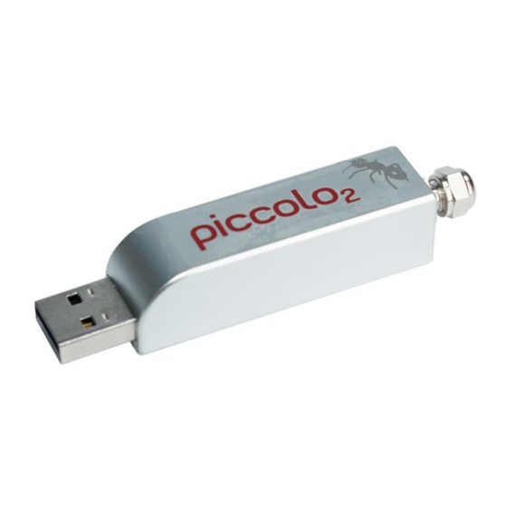
1 Overview The ultra-compact Piccolo2 is a fiber-optic oxygen meter integrated in a small USB stick housing. Despite its small size, it features the proven REDFLASH technology from Pyro Science (see Appendix 10.3 for more details). The Piccolo2 can be used in... -
Page 6: Safety Guidelines
(optodes) from Pyro Science. In order to guarantee an optimal performance of the Piccolo2, please follow these operation instructions and safety guidelines. Please note that opening the housing will void the warranty. There are no serviceable parts inside the device. - Page 7 Before using the Piccolo2 and the sensors, carefully read the instructions and user manuals. In case of problems or damage, disconnect the instrument and mark it to prevent any further use! Consult Pyro Science advice! There are no serviceable parts inside the device. Please...
-
Page 8: Introduction To The Piccolo2
3 Introduction to the Piccolo2 Piccolo2 is a miniature USB-driven fiber-optic oxygen meter for usage in the laboratory. It is compatible to a variety of oxygen sensors from Pyro Science, like robust probes, dipping probes and contactless sensors, including sensor spots, respiration vials, flow- through cells and nanoprobes. -
Page 9: Software Installation
4 Software Installation IMPORTANT: Do not connect the Piccolo2 to your PC before the Pyro Oxygen Logger software has been installed. The software will install the appropriate USB-drivers automatically. System requirements: PC or tablet with Windows XP / Vista / 7 / 8 / 10 (but not Windows RT) and min. -
Page 10: Oxygen Sensor Types
5 Oxygen Sensor Types For the Piccolo2 meter, Pyro Science offers a range of optical oxygen probes and contactless oxygen sensors, comprising sensor spots, flow-through cells, respiration vials and nanoprobes. For an overview of all available oxygen sensor types, please visit the... -
Page 11: Dipping Probe
5.2 Dipping Probe Characteristics: dipping probe for Piccolo2 (item no. OPDIP20) with stainless steel tubing 3 mm in diameter and 200 mm in length oxygen sensor with optical isolation located in the 3 mm disc at the tip of the tubing (sensor end, see chapter 5.7) - Page 12 PICFIB2: black fiber cable, 3 mm in diameter, 1 m in length, connecting the basic spot adapter SPADBAS with the Piccolo2 meter (see also chapter 5.7) or, alternatively, optical fiber rod PICROD2: stainless steel tubing, 3 mm diameter,...
-
Page 13: Flow-Through Cells
Note: A change of position of the spot adapter after calibration of the sensor spot might require a new calibration. Accessories for readout: 10-20 mm thick transparent windows optical fiber rod PICROD3: ca. 50 mm in length, needs a customized fixation on the outer container wall (not compatible with the spot adapter SPADBAS) The optical fiber rod... -
Page 14: Respiration Vials
3.0-4.0 mm to the OXFTC2 Accessories for readout: optical fiber PICFIB2: black fiber cable, 3 mm in diameter, 1 m in length, connecting the flow-through cell with the Piccolo2 meter (see also chapter 5.7) Applications: contactless measurement of oxygen in a... - Page 15 optical fiber PICFIB2: black fiber cable, 3 mm in diameter, 1 m in length, can be fixed in the adapter ring with the clamping screw, connecting the respiration vial with the Piccolo2 meter (see also chapter 5.7) Applications: ...
-
Page 16: Nanoprobes
optical fiber PICFIB2: black fiber cable, 3 mm in diameter, 1 m in length, connecting the basic spot adapter with the Piccolo2 meter (see also chapter 5.7) or, alternatively, ... - Page 17 optical fiber rod with integrated focusing lens PICROD2-LNS: stainless steel tubing, 3 mm in diameter, 40 mm in length, connecting the basic spot adapter or custom fixation with the Piccolo2 meter (see also chapter 5.7) Applications: real-time monitoring ...
-
Page 18: Connecting The Sensors And Optical Fibers
First, remove the protective caps from both ends of the optical probe / fiber / rod. Then slightly unscrew and loosen the nut at the sensor port of the Piccolo2. The nut must not be removed from the sensor port. Typically, unscrewing the nut with a single half turn (180°) is sufficient. - Page 19 Insert the optical probe / fiber / rod carefully as deep as possible (ca. 24 mm) into the sensor port of the Piccolo2! Fix the optical probe / fiber / rod by screwing down the nut tightly onto the sensor port of the Piccolo2.
-
Page 20: Cleaning And Maintenance Of The Sensors
5.8 Cleaning and Maintenance of the Sensors Oxygen sensors for the Piccolo2 can be sterilized with ethylene oxide (EtO) and can be cleaned with ethanol, peroxide (3% H2O2) or soap solution. They can be applied in gas phases, in aqueous... - Page 21 surface sufficiently with demineralized water afterwards to remove small particles and let it dry before storage. After drying, put the respiration vials into the corresponding black bag and store them in a secure, dry and dark place at room temperature! Store sensors in a dry, dark and secure place at room temperature.
-
Page 22: The Software "Pyro Oxygen Logger
6 The Software "Pyro Oxygen Logger" This chapter describes all functions of the Pyro Oxygen Logger software excluding sensor calibration, which is described in detail in chapter 7 and 9. 6.1 Main Window After start of the Pyro Oxygen Logger software the following main window is shown: As default, uncalibrated oxygen sensor readings (raw value) are... - Page 23 The sensor readings are displayed in a numeric display (D) and in a chart recorder (C) in the chosen oxygen unit (UD). The color and appearance of each graph can be changed by clicking on the color- control (CC), opening a pop-up menu.
- Page 24 Avoid direct sun light exposure or strong direct illumination with a lamp. (For advanced users: decrease the LED intensity and / or the amplification in the Advanced Settings) Bad reference This indicates internal problems of the Piccolo2. Please contact Pyro Science for support.
- Page 25 6.2. The button Save Setup can be used to save the current settings and calibration data of the Piccolo2. They can be reloaded anytime by pressing the button Load Setup. This allows e.g. to switch between different laboratory setups with a single Piccolo2.
- Page 26 Piccolo2 meters. The different windows operate completely independent of each other and are assigned to exactly one Piccolo2. This allows measurements in different setups at the same time. The flashing of the status LEDs can help to assign a specific logger window to the...
- Page 27 A Measurement is started by clicking on the measurement start button (MSB). The arrow in the button turns from dark green to light green indicating that a measurement is in progress. Clicking on it again will stop the measurement. The mode of Measurement can be chosen as single data point acquisition, continuous sampling (default setting) or as continuous sampling limited to a defined time interval.
- Page 28 IMPORTANT: By default the displayed data are not automatically saved to a data file. To activate data logging, click on the red start button (SB) of Log to File. Select a file name in the appearing file dialog. The saved data files are simple text-files with the file extension ".txt", which can be imported easily into common spreadsheet programs.
- Page 29 The display of the data in the charts can be changed by different chart tools arranged underneath the chart recorder. The button with the magnifying glass offers different zoom options. After clicking the button with the hand, the user can click on the chart and move the whole area while keeping the mouse button pressed.
-
Page 30: Settings
6.2 Settings To open the dialog window Piccolo2 Settings click on the Settings button in the Main Window: The Settings can be adjusted only when data logging is not active. In the Settings the user has to enter the Sensor Code of the... -
Page 31: Basic Settings
Piccolo2 is entered into the field Sensor Code in the Channel 1 tab of the window Piccolo2 Settings. It includes information for optimal sensor settings and for calibration data needed for the (rough) factory calibration and for the 1-point calibration. The first letter of the sensor code defines the sensor type. -
Page 32: Advanced Settings
thereby changing the oxygen measuring time. For standard applications, an intermediate mode (8 or 16) is advisable. The Fiber Length (m) of the connected robust probe (OPROB3) or of the connected optical fiber (PICFIB2) for contactless sensors must be entered, which is typically 1 m (refer to chapter 9.2 for more details). -
Page 33: Conditions In The Sample
NOTE: If using the Advanced Sensor Settings, it is recommended to perform a 2-Point calibration of the oxygen sensor. Later readjustments in the Advanced Settings might require also new calibration of the sensor. The Fiber Length (m) of the connected robust probe (OPROB3) or of the connected optical fiber (PICFIB2) for contactless sensors must be entered, which is typically 1 m (refer to chapter... -
Page 34: Options
6.2.4 Options In the panel Options, it is possible to designate a specific name to the connected Piccolo2 by typing a name in the field Device Name e.g. "water sample #12". This device name is then displayed in the top line of the main window. This option is useful especially if... - Page 35 The maximum number of data points kept in the graphs can be changed by the selector Max. Data Points in Graphs (default: 10800). A change of the number of data points will clear the graphs, and high values (>>10000) might decrease the maximum sample rate (increase the actual sample interval).
-
Page 36: Raw Data Window
Ambient Light (in mV) gives a measure of the ambient light entering the sensor from outside. At too high ambient light levels, the detector of the Piccolo2 might get saturated, indicated by the warning Signal too high in this window and in the warning display of the main window. - Page 37 On the right side of the channel tab, a graph can be activated, showing the dphi (°) and Signal Intensity (mV) in the graph (default setting). Plotting of additional parameters can be activated by clicking on the small rectangular button next to the color control of the respective parameter.
-
Page 38: Calibration Of Oxygen Sensors
7 Calibration of Oxygen Sensors This chapter describes the possible calibration modes for oxygen sensors connected to the Piccolo2 meter using the logger software Pyro Oxygen Logger. For sensor calibration, the temperature in the calibration standard, the atmospheric pressure and the relative humidity of the ambient air are important parameters ensuring high precision of calibration. -
Page 39: Calibration Mode: Factory
Factory calibration (for a quick, rough calibration): taking the 0% and the air calibration values from the sensor code; advised only for rough measurements or testing purposes. 1-Point: taking the 0% value from the sensor code and the air calibration value from a manual calibration for precise measurements around 21% O2. -
Page 40: Calibration Mode: 1-Point
If the calibration mode Factory Calibration is chosen, ensure that the correct sensor code has been entered in the Settings (as displayed in 2. Adjust Calibration Conditions of the Oxygen Sensor Calibration window). If the sensor code displayed is not correct, click on Finish, open Settings, enter the correct Sensor Code and repeat Factory Calibration. - Page 41 The temperature of the calibration standard needs to be measured, kept constant and entered manually in Fixed Temperature. In addition, the actual atmospheric pressure in the calibration standard can be entered manually in Pressure (mbar). Normal conditions refer to 1013 mbar (default setting). If the actual atmospheric pressure cannot be determined on site, alternatively it is possible to enter the actual Elevation (m) in meters above sea level.
-
Page 42: Calibration Mode: 2-Point
Wait for steady-state until the sensor reading is stable by observing the graph. Also ensure stable temperature during calibration. Note that the button Set Air will be highlighted as soon as the oxygen reading is within the expected range for the connected sensor type (the latter does not apply for custom air calibration with ≠20.95% O2). - Page 43 NOTE: Ensure constant calibration conditions and a constant temperature in the calibration standard! Wait for steady-state until the sensor reading is stable by observing the graph. Ensure also stable temperature conditions in the standard during calibration. Note that the button Set Air will be highlighted as soon as the oxygen readings are within the expected range for the connected sensor type (the latter does not apply for custom air calibration with ≠20.95% O2).
-
Page 44: Calibration Mode: Custom
Note that the button Set 0% will be highlighted as soon as the oxygen readings are within the expected range for the connected sensor type. If the oxygen sensor readings have reached their steady-state, click on Set 0%, and the current oxygen sensor reading is taken for 0% calibration. -
Page 45: Advanced Adjustments
This section is for advanced users only! For very advanced applications, it is possible to manipulate all internal calibration parameters of the Piccolo2 manually. This option is accessible by selecting Custom Mode and subsequently clicking on Advanced: Adjust Manually, which opens a separate window showing all internal calibration parameters. - Page 46 Further, the phase shift "dphi" (dphi, see chapter 10.3) for the 0% calibration standard (dphi 0% in °) and for the air calibration standard (dphi 100% in °) can be adjusted manually. The Background Amplitude (in mV) and the Background dphi (phase shift in °) can be adjusted (refer to chapter 9.2 for more details).
-
Page 47: Calibration Standards
8 Calibration Standards 8.1 The Air Calibration Standard The Air Calibration standard can be ambient air water-vapor saturated air air saturated water (100% air saturation) Always use a proper lab stand for mounting the oxygen sensor! All air calibration standards described in the following rely on the virtually constant oxygen content in the earth’s atmosphere of about 20.95% O2 in dry air. - Page 48 (1) The relative humidity and the temperature of the ambient air must be determined during calibration and entered into the software. Then, the Pyro Oxygen Logger software will automatically calculate the real oxygen level under these conditions. (2) The calibration standard is prepared in a closed vessel either filled with water or partly filled with e.g.
-
Page 49: Ambient Air
2. Adjust Calibration Conditions of the Oxygen Sensor Calibration window. Ensure that these three parameters are kept constant during the calibration procedure. Then, the dry oxygen sensor connected to the Piccolo2 is exposed to the ambient air. Otherwise, follow the calibration procedures given in chapter 7. -
Page 50: Air Saturated Water
the oxygen sensor and a temperature sensor. Otherwise, follow the calibration procedures given in chapter 7. 8.1.3 Air Saturated Water Fill an appropriate amount of water into a flask (e.g. Duran flask) with a lid prepared with holes for inserting the oxygen sensor and a temperature sensor. -
Page 51: The 0% Standard
8.2 The 0% Standard The 0% calibration standard can be water mixed with a strong reductant water flushed with nitrogen gas (N nitrogen gas (N 8.2.1 Water Mixed with a Strong Reductant Fill an appropriate amount of water into a glass flask (e.g. Duran flask) with a lid prepared with holes for inserting the oxygen sensor and a temperature sensor. -
Page 52: Nitrogen Gas
Please consider that streaming N2 gas through water may cause cooling of the water. Ensure correct temperature determination of the 0% calibration standard! 8.2.3 Nitrogen Gas Flush 100% nitrogen gas through a glass flask (e.g. Duran flask) with a lid prepared with holes for inserting the oxygen sensor and a temperature sensor. -
Page 53: Calibration Of Contactless Sensors
9 Calibration of Contactless Sensors For preparing a setup with contactless oxygen sensors, please refer to the chapters 5.3-5.7. More details on oxygen nanoprobes in microfluidic applications are available on request. 9.1 Calibration Procedure In general, the calibration procedure for contactless sensors (e.g. sensor spots, flow-through cells, respiration vials) is the same as for the robust and dipping probe described in chapters 7 and 8. -
Page 54: Manual Background Compensation
Piccolo2 with the contactless oxygen sensor. Based on the Fiber Length (m) entered in the Settings (see chapters 6.2.1 and 6.2.2), a background signal for compensation is estimated automatically by the... - Page 55 the instrument end of the Optical Fiber is connected to the Piccolo2 (see 5.7) and the adapter end of the Optical Fiber attached to the sensor (i.e. disconnect the adapter end from the spot adapter, adapter ring or from the flow-through cell) Then, wait for steady-state and press the button Take Actual Values.
-
Page 56: Appendix
10 Appendix 10.1 Specifications of the Piccolo2 Dimensions 15.5 x 15.5 x 54 mm Weight ca. 20 g Interface USB 2.0 Power Supply 5VDC from USB-port, ca. 3-5mA average current consumption with max. 40mA peaks (of about 10- 200ms duration) during an oxygen... -
Page 57: Troubleshooting
10.2 Troubleshooting How to respond to the warnings shown in the Pyro Oxygen Logger software: Signal Too High Too much ambient light exposed to the sensor, or amplification is too high, or LED intensity is too high: → darken the surrounding →... -
Page 58: Measuring Principle
10.3 Measuring Principle REDFLASH technology is based on the unique oxygen- sensitive REDFLASH indicator showing excellent brightness. The measuring principle is based on the quenching of the REDFLASH indicator luminescence caused by collision between oxygen molecules and the REDFLASH indicator immobilized on the sensor tip or surface. - Page 59 The measuring principle is based on a sinusoidally modulated red excitation light. This results in a phase-shifted sinusoidally modulated emission in the NIR. The Piccolo2 measures this phase shift (termed "dphi" in the software). The phase shift is then converted into oxygen units based on the Stern-Vollmer-Theory.
-
Page 60: Operating Several Piccolo2 In Parallel
Pyro Oxygen Logger software now has to be started separately for each connected Piccolo2. So, if you want to operate e.g. 4 different Piccolo2, you have to start the Pyro Oxygen Logger software 4 times, which will open 4 Pyro Oxygen Logger windows on your desktop. -
Page 61: Definition Of Oxygen Units
Used in: gas and water phase For a calibrated sensor, the partial oxygen pressure p in units of hPa (equivalent to mbar) is the fundamental oxygen unit measured by the Piccolo2. partial pressure p Torr Definition: [Torr] = p [hPa] x 759.96 / 1013.25... - Page 62 % air saturation A % air sat Definition: A[% a.s.] = 100% x p / p100 Used in: water phase with p100 = 0.2095 ( p – p (T) ) (T) = 6.112mbar x exp ( 17.62 T[°C] / (243.12 + T[°C])) actual partial pressure actual barometric pressure actual temperature...
-
Page 63: Table Of Oxygen Solubility
10.6 Table of Oxygen Solubility The following table shows the equilibrium oxygen concentration (T, P=1013mbar, S) in units of µmol/L at standard atmospheric pressure of 1013 mbar as a function of water temperature in units of °C and salinity in units of PSU ("practical salinity unit" ≈ g/L). In order to correct these values for the actual atmospheric pressure , the following formula has to be applied: (T,P,S) = C... - Page 64 Temp (°C) (PSU) 456.6 398.9 352.6 314.9 283.9 257.9 235.9 217.0 200.4 450.4 393.6 348.1 311.1 280.6 255.0 233.3 214.7 198.3 444.2 388.5 343.7 307.3 277.3 252.1 230.8 212.4 196.3 438.1 383.3 339.4 303.6 274.0 249.3 228.3 210.2 194.3 432.1 378.3 335.1 299.9...
-
Page 65: Explanation Of The Sensor Code
10.7 Explanation of the Sensor Code The oxygen sensors are delivered with an attached sensor code which has to be entered in the Settings (refer to chapter 6.2). The following figure gives a short explanation about the information given in the sensor code. XB7-532-205 Example Code: Sensor Type... - Page 66 C0 (Factory Calibration at 0% O2) dphi0 = C0 / 10 C100 (Factory Calibration at 100% O2) dphi100 = C100 / 10 The values of factory calibration are valid for the following calibration conditions: Partial Volume of Oxygen (% O2) 20.95 Temperature at both calibration points (°C) 20.0...
Need help?
Do you have a question about the Piccolo2 and is the answer not in the manual?
Questions and answers